2020_Breve descrizione sul metodo NATM.pdf
•
0 likes•248 views

Brief description on the anchoring and nailing of the rock during the excavation of railway tunnels with the traditional NATM Method (New Austrian Tunneling Method). In Italian and English

Recommended
Recommended
More Related Content
What's hot
What's hot (15)
Similar to 2020_Breve descrizione sul metodo NATM.pdf
Similar to 2020_Breve descrizione sul metodo NATM.pdf (20)
More from FONDAZIONE INT.LE CENTRO STUDI E RICERCHE-ONLUS (NGO)
More from FONDAZIONE INT.LE CENTRO STUDI E RICERCHE-ONLUS (NGO) (20)
2020_Breve descrizione sul metodo NATM.pdf
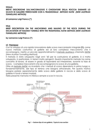
- 1. 1 TITOLO: BREVE DESCRIZIONE SULL’ANCORAGGIO E CHIODATURE DELLA ROCCIA DURANTE LO SCAVO DI GALLERIE FERROVIARIE CON IL TRADIZIONALE METODO NATM (NEW AUSTRIAN TUNNELLING METHOD) di Lamanna Luigi Franco (*) TITLE: BRIEF DESCRIPTION ON THE ANCHORING AND NAILING OF THE ROCK DURING THE EXCAVATION OF RAILWAY TUNNELS WITH THE TRADITIONAL NATM METHOD (NEW AUSTRIAN TUNNELLING METHOD) by Lamanna Luigi Franco (*) a)- Premessa Con lo sviluppo di una rapida innovazione dello scavo meccanizzato integrale (1), come nuovo metodo costruttivo di gallerie ed al loro complesso meccanismo che li accompagna, merita un piccolo approfondimento il metodo austriaco chiamato NATM (New Austrian Tunnelling Method). Il metodo è stato sviluppato negli anni ’60 per la costruzione di gallerie, è si molto sviluppato, in particolare, in terreni molto spingenti. Questo importante metodo ha come concetto di lavoro, di essere in grado di rispondere ed interpretare, durante la fase di scavo, i complessi meccanismi che accompagnano lo scavo di una galleria. Oltre al metodo NATM va ricordato che i metodi di scavo dipendono in primo luogo e, fondamentalmente, dal tipo di terreno che bisogna attraversare. Per questo motivo bisogna parlare separatamente dello scavo delle gallerie in roccia e dello scavo di gallerie in fondi o terreni morbidi. Nella presente memoria mi riferisco sempre a scavi in roccia. Fig 1 – Sezione tipo di una galleria / Typical cross section WATERPROOFING ROCK BOLTS TIPO “PERFO” 20 cm SHOTCRETE INTERNAL CONCRETE LINING 30 cm INTERNAL CONCRETE LINING 30 cm INVERT ARCH
- 2. 2 Nello scavo meccanico l’energia utilizzata si concentra sull’estremità dell’attrezzatura presente sulla macchina a contatto con la roccia (martelli idraulici azionati ad aria compressa), in modo da superare la resistenza della roccia, nel momento della penetrazione o della dentellatura, e la resistenza a trazione o frantumazione. b)- Breve descrizione del metodo NATM Nel proseguire nella nostra argomentazione, la stabilizzazione della superficie di scavo con il metodo NATM avviene mediante la messa in opera di: - l’uso dell’acciaio per le centine che, trattasi di un metodo di consolidamento e ripristino strutturale di una galleria esistente o in presenza di struttura deformata da terreni spingenti; - l’introduzione di idonea chiodatura e ancoraggi della roccia, sia che sia del tipo passivo che attivo, ha lo scopo di prevenire i rilasci e ridurre la decompressione, in modo che la roccia circostante non perde la sua resistenza e può quindi collaborare a modo d’arco. Questa collaborazione può essere sfruttata in modo ottimale, adottando lo spessore del successivo rivestimento in Spritz-Beton; Fig 2 – Sezione A-A Barra Ø 26 posizionata in fori Ø 40 mm / Section A-A Bar Ø 26 positioned in holes Ø 40 mm - stabilizzazione della roccia o del terreno per controllarne le deformazioni consentendo così la ridistribuzione delle tensioni evitando nel contempo dei distacchi localizzati mediante Spritz-Beton (termine in lingua Tedesca) o Shotcrete (termine in lingua inglese). L’utilizzo di questa tecnica permette di proiettare mediante un getto d’aria compressa una miscela base formata da conglomerato cementizio, additivata con l’aggiunta del silicato di sodio che fornisce al conglomerato una capacità di adesione [aderenza (per ROCK BOLTS TIPO “PERFO” Bar Ø 26 positioned in holes Ø 40 mm ROCK
- 3. 3 taglio al substrato): 2,8 – 6,0 MPa] istantanea ed efficace (chiamata tecnicamente “flash set”), fibre (2), acqua ed aggregati (la sabbia o le sabbie devono avere un modulo di finezza combinato compreso tra 2,5 e 2,9 e passanti ai setacci nr. 50 (300 µm) e nr. 100 (150 µm) rispettivamente comprese tra il 15% al 30% e il 5% al 10% [per la pompabilità degli impasti]) che, immediatamente dopo ‘allontanamento dello smarino, mediante una lancia ad aria compressa, viene spruzzato ad alta velocità sulle superfici da rivestire, come stabilizzatore della stessa roccia. Il silicato di sodio è senza dubbio è il più diffuso accelerante di presa, conosciuto ed utilizzato nel mondo. Si ottiene per dissoluzione della silice SiO2 (diossido di silicio) e della soda Na2O in acqua secondo un combinato ciclo termodinamico. Il silicato di sodio, non è il solo responsabile delle caratteristiche di presa dello Spritz- Beton, specialmente sulle superfici bagnate, ma fungono anche a questa azione gli: - Iperfluidificanti (si distingue dai tradizionali superfluidificanti, a base di polimeri solfonati, i quali provocano la dispersione dei granuli di cemento per effetto elettrostatico permettendo al calcestruzzo proiettato delle resistenze molto elevate – Rck ³ 75 MPa); - Acceleranti (migliorano la prestazione del calcestruzzo sul grado di idratazione provocandone un più rapido aumento ai tempi brevi, ma lasciandone sostanzialmente immutato il valore a tempi relativamente lunghi (28 giorni); - Impermeabilizzanti (è un additivo liquido perfettamente solubile in acqua, privo di cloruri, inoffensivo per le armature metalliche, in grado di rendere la miscela stabile e a forte effetto idrofugo). Inoltre questa metodologia ha il vantaggio di essere molto adattabile e flessibile. Naturalmente non ci si deve trovare in presenza di forti venute d’acqua (3) verso l’interno del cavo della galleria, argomentazione più volte affrontata dal sottoscritto. Comunque, questa metodologia richiede un rivestimento cementizio di dimensioni ridotte rispetto ad altri metodi conosciuti. b.1)- Controllo dello stato deformativo e tensionale Un’altra caratteristica del sistema NATM è l’intensivo impiego di misurazioni geotecniche, per verificare il comportamento di sistema pre-rivestimento-ammasso roccioso, per poter adattare la struttura del rivestimento, in caso di modifiche del comportamento pronosticato. In particolare MUELLER (1978) ha introdotto il ruolo importante svolto dalla misurazione dello stato deformativo e tensionale all’intorno della galleria, durante lo scavo, con lo scopo di ottenere delle informazioni relative al comportamento dell’ammasso roccioso e, quindi, di aggiornare in modo continuo il dimensionamento delle strutture di sostegno. Considerando che il sistema NATM utilizza per la stabilizzazione della roccia quasi esclusivamente lo Spritz-Beton (e gli ancoraggi), ritengo opportuno illustrare le caratteristiche principali che questo deve possedere: - peso di volume secco: 2,0 – 2,5 t/m3; - modulo di elasticità a 28 gg: 20.000 – 30.000 N/mm2; - resistenza a compressione a 28 gg: 30 – 50 N/mm2; - resistenza a compressione a 7 gg: 75-85 % della resistenza a compressione a 28 gg; - resistenza a trazione a 28 gg: 1,5 – 4 N/mm2;
- 4. 4 - permeabilità secondo Darcy: 1 - 25.10-10 m/sec; - aderenza al calcestruzzo: 0,5 – 4 N/mm2. Fig. 3 – Rock Bolting/Anchoring b.2)- Ancoraggio alla roccia Con il metodo NATM le gallerie vengono scavate con metodo tradizionale secondo le seguenti fasi: - scavo, eseguito con martelli idraulici azionati ad aria compressa oppure mediante esplosione in base al comportamento del terreno pronosticato; - allontanamento dello smarino (detriti); - messa in sicurezza attraverso la messa in opera di un pre-rivestimento con elementi strutturali di sostegno metallici (centine) e da Spritz-Beton armato (rivestimento). In particolare l’ancoraggio alla roccia, oggetto su cui ci vogliamo concentrare più in dettaglio all’interno di questo articolo, avviene attraverso un elemento strutturale operante in trazione, atto a trasmettere forze al terreno. Le parti funzionali dell’ancoraggio sono: - il dispositivo di bloccaggio e la piastra di ripartizione posta in testata; - l’armatura costituita da barre o profilati in acciaio o in fibra di vetro; - il dispositivo di ancoraggio ad espansione meccanica, o come meglio vogliamo sottolineare di seguito, per mezzo di un particolare formulato di resina silicatica (organo-minerale e non inquinante), nel tratto terminale dell’elemento strutturale onde garantire una perfetta unione tra roccia e barra. Nel recente passato, per non dire ancora oggi, il fissaggio avveniva attraverso l’iniezione di una malta cementizia. Vorrei sottolineare che la forza dell’ancoraggio dipende dalla resistenza dell’armatura, dall’aderenza tra roccia e barra (cosa che viene garantita dall’iniezione del formulato di resina silicatica) e dalla natura del terreno. Va ricordato che un altro presupposto indispensabile per l’impiego del metodo NATM è la presenza di un terreno più o meno omogeneo, ciò per garantire che le condizioni tra il sottile rivestimento superficiale cementizio (Spritz-Beton) e la roccia siano simili lungo tutta la linea di scavo. Caso contrario si rischia, in corrispondenza del contatto (roccia/rivestimento) dei fenomeni deformabilità e valori di resistenza, molto differenti, e di conseguenza il verificarsi di sollecitazioni che andranno a concentrarsi nel rivestimento, cioè la rottura istantanea di quest’ultimo.
- 5. 5 c)- Caratteristiche ed indicazioni generali sulle barre (bulloni) Nella tecnologia degli ancoraggi sono disponibili sul mercato diversi tipi di bulloni: - a filetto integrale (barre piene o forate); - autoperforanti; - a cavi. I primi, sono stati sviluppati per supportare i carichi in strati rocciosi sul fronte di scavo. Hanno una filettatura integrale e continua che consente una facilità di taglio su misura ed una forte adesione laterale durante la fase di iniezione. Inoltre presentano una elevata resistenza alla trazione conferendo al bullone una notevole capacità di assorbimento del carico e un fissaggio permanente. Le seconde, o barre autoperforanti, vengono utilizzati quando ci troviamo sul fronte di scavo in presenza di rocce tenere sino ad un massimo di 80 MPa di resistenza alla torsione, rocce fratturate oppure in materiali sciolti e questi sono ideali all’iniezioni mediante qualsiasi tipo di formulato chimico. Infine, i tiranti a cavi in vetroresina e non, vengono impiegati quando si scavano gallerie parallele o gallerie pilota o di esplorazione. Fig. 4 – Sistema di supporto della roccia dove viene ancorata la barra e diversi fattori che intervengono nella corrosine (dei bulloni) / Rock support system where the bar is anchored and various factors that intervene in the corrosion (of the bolts) d)- Caratteristiche ed indicazioni generali della resina per garantire l’ancoraggio della barra con la roccia Da una nostra analisi, con la collaborazione dei dati forniti dalla CHEMIX di Golasecca (Varese) (**), sull’ individuare un prodotto idoneo ai problemi che andremo ad incontrare, durante la fase di scavo di una galleria ferroviaria in territorio europeo, con l’inizio dell’anno 2021, ci siamo prefissi, per dei fissaggi permanenti, con dei bulloni, e la nostra attenzione è andata su un formulato a base di silicato-mineral-organico, a due componenti. Primo, perché questo formulato è stato sviluppato e sperimentato, rispondendo alle principali domande in fatto di gallerie; secondo, perché ci permetteva di interpretare i complessi meccanismi che accompagnano lo scavo di una galleria; ed in ultima analisi, ci ha permesso di prendere in considerazione la sua particolarità di poter FLOW AMOUNT & VELOCITY PRESSURE TEMPERATURE GROUND MOVEMENT STRATA’S CONDUCTIVITY GASES CO 2 SO 2 O 2 STRESSES RESIN ROOF BOLT GROUND WATER PH SULFATES CHLORIDES NITRATES LIME STONE GRAY SHAL SHALE COAL
- 6. 6 essere iniettato in piccoli interstizi, a differenza dei prodotti a base cementizia, che tende, oltre ad altre cause, a segregarsi ed a indebolire il bullone con il passare del tempo. Inoltre, questo formulato a base di silicato-mineral-organico è in grado di partecipare ad assorbire parte del carico, anche in tempi molto brevi, e cosa molto importante stabilizzare il fronte di scavo e, ai fini della sicurezza, possedere caratteristiche di “atossicità” ed “autoestinguenza”: • Peso specifico componente “A” : 1,450 ± 0,03 kg/dm³ • Peso specifico componente “B” : 1,180 ± 0,05 kg/dm³ • Viscosità componente “A” : 300 - 600 ± 30 mPa.s • Viscosità componente “B” : 250 - 750 ± 50 mPa.s • pH componente “A” : 11,5 ± 0,5 • pH componente “B” : neutro • Inizio della reazione : 20 – 30“ • Reazione completa : dopo 2 – 3’ • Esotermia di reazione : max 90 – 100°C (su massa di 200 gr) • Resistenza a compressione : 28 – 30 N/mm² • Resistenza a flessione : 5,50 – 6,18 N/mm² Il formulato resinoso sopra descritto è una resina a reazione di indurimento veloce a base di silicati. Quando i due componenti vengono a combinarsi, la resina incrementa la sua viscosità diventando tixotropica, scorrendo in grosse e piccole cavità attraverso specifiche pompe. Fig. 6 - Effetti della corrosione su barre in roccia iniettati con malta cementizia dopo soli 6 mesi. (Spearing et al., 2010) / Effects of corrosion on rock anchors injected with cement mortar after only 6 months. (Spearing et al., 2010) g)- Conclusioni Sul metodo NATM esiste una vasta gamma di pubblicazioni sia di carattere generale che su esperienze specifiche. Mentre lo scopo della nostra memoria è quello di richiamare l’attenzione su come alcuni particolari tipi di resine stiano partecipando alla rapida evoluzione in corso dei nuovi metodi costruttivi delle gallerie. La moderna tecnologia offre un vasto panorama di soluzioni per l’introduzione delle iniezioni di cemento come utile mezzo per il riempimento di eventuali vuoti anche con microcemento. Infatti, per consolidare la roccia, circostante una cavità, la boiacca di cemento è oramai superata dall’impiego di nuovi formulati resinosi a base di silicati (privi di CFC e alogeni) perché questi induriscono in pochi minuti e perché anche le stesse
- 7. 7 resine possono partecipare a supportare parte del carico in breve tempo ed essere in grado di combinarsi alle particolari condizioni geologiche che si presentano. I principali fattori che mi permette di asserire, quanto sopra illustrato, sono da individuare nelle caratteristiche geotecniche della roccia e nella definizione delle caratteristiche fisico-meccaniche della resina. Il principio di funzionamento delle iniezioni di resina a bassa pressione risiede che questa è in grado di riempire ed occludere ogni porosità ed ogni microfessurazione presente sulla natura della roccia, nel contorno e nelle vicinanze del foro contenente la barra di acciaio, cosa che i grani di cemento (sedimentazione propria della boiacca cementizia iniettata) ed i pori più piccoli (non penetrabili dalla fase solida) di fatto ne impedirebbero la penetrazione riducendo il raggio d’influenza. NOTE 1. I metodi di costruzione meccanizzato integrale sinora conosciuti in Europa sono: - Il metodo di scavo meccanizzato, ad abbattimento continuo, per la costruzione di gallerie con attacco a piena sezione mediante frese integrali (TBM), di tipo aperto o scudato, senza o con contropressione al fronte; - Il metodo di scavo meccanizzato, ad abbattimento continuo, per la costruzione di gallerie con attacco a piena sezione, in terreni anche sottofalda, mediante scudi meccanizzati, con contropressioni al fronte. 2. Esistono circostanze operative particolari come il rafforzamento di gallerie, terreni o la ristrutturazione di strutture preesistenti, che richiedono l’utilizzo di speciali fibre di rinforzo. Abbiamo quindi: 2.1- fibre in acciaio. Le metalliche ed in filato di vetro, vengono utilizzate per il miglioramento della duttilità, della tenacità e della resistenza all’urto del calcestruzzo. Per quanto riguarda il dosaggio delle fibre nel calcestruzzo, normalmente, vengono impiegate fibre in acciaio con contenuti di 35-45 kg/m3, fibre in filato di vetro, resistenti all'attacco degli alcali, nella quantità di 8-12 kg/m3 (questi quantitativi sono suggeriti dai produttori). E’ importante sottolineare che tali calcestruzzi fibrorinforzati vengono di solito impiegati per consolidare fronti di gallerie, terreni e/o rinforzare strutture preesistenti, con o senza l’utilizzo di armatura metallica in barre o rete. 2.2- fibre polimeriche non strutturali, utili per incrementare la resistenza alla microfessurazione nelle ore successive alla posa in opera; 2.3- fibre polimeriche strutturali in filato di vetro, che migliorano la duttilità e la resistenza all’urto del calcestruzzo. 3. Tra le condizioni idrogeologiche più pericolose vanno annoverate le situazioni stratigrafiche o tettoniche che comportano il passaggio brusco da formazioni impermeabili a permeabili, sedi di cospicuo accumulo idrico. Particolare importanza assumono le rocce fessurate, soprattutto quelle calcaree, che possono contenere forti quantitativi di acqua in pressione, talora anche ad elevata temperatura. (*) Mr. LAMANNA LUIGI FRANCO 132, via dei Serpenti – 00184 ROME – ITALY - U.E. e-mail: lamannaluigifranco1 @ gmail.com
- 8. 8 (**) The CHEMIX products serve many industries such as Automotive, Motorsports, Aerospace, Tooling, Nautica, Prototyping, Composites, Design, Electric, Foundry, Construction (Tunnelling, Engineering and Mining). The company has a modern equipped laboratory for the physical characterization, thermal analysis and mechanical tests; production units with mixing and dispersion equipment, packaging and storage. We are in Golasecca (Varese) - Italy, in the green Park of Ticino, 5 km from the A8 motorway and 10 km from Milan Malpensa International Airport. CHEMIX offers over 18 years of experience in reactive high-performance polymers. Through constant innovation and development, we provide a wide range of polyurethane and epoxy systems. We devote significant resources to the development of ever more efficient systems with a continued investment of profits in technologically advanced equipment and instrumentation. E-mail: info @ chemix.it …..oo0oo….. TITLE: BRIEF DESCRIPTION ON THE ANCHORING AND NAILING OF THE ROCK DURING THE EXCAVATION OF RAILWAY TUNNELS WITH THE TRADITIONAL NATM METHOD (NEW AUSTRIAN TUNNELLING METHOD) by Lamanna Luigi Franco (*) a)- Introduction With the development of a rapid innovation of the integral mechanized excavation (1), as a new construction method of tunnels and their complex mechanism that accompanies them, the Austrian method called NATM (New Austrian Tunneling Method) deserves a little study. The method was developed in the 1960s for the construction of tunnels, and has developed greatly, in particular, in very demanding soils. This important method has as its working concept, to be able to respond and interpret, during the excavation phase, the complex mechanisms that accompany the excavation of a tunnel. In addition to the NATM method, it should be remembered that the excavation methods depend first and foremost on the type of terrain to be crossed. For this reason it is necessary to speak separately of the excavation of tunnels in rock and the excavation of tunnels in bottoms or soft soils. In this memoir I always refer to rock excavations. Fig 1 – Sezione tipo di una galleria / Typical cross section INTERNAL CONCRETE LINING 30 cm 20 cm SHOTCRETE ROCK BOLTS TIPO “PERFO” ROCK BOLTS TIPO “PERFO” WATERPROOFING INTERNAL CONCRETE LINING 30 cm INVERT ARCH
- 9. 9 In mechanical excavation, the energy used is concentrated on the extremity of the equipment present on the machine in contact with the rock (hydraulic hammers operated by compressed air), in order to overcome the resistance of the rock, at the moment of penetration or indentation, and resistance to traction or crushing. b) - Brief description of the NATM method In continuing our argument, the stabilization of the excavation surface with the NATM method takes place through the implementation of: - the use of steel for the ribs which, being a method of consolidation and structural restoration of an existing tunnel or in the presence of a structure deformed by pushing soils; - the introduction of suitable nailing and anchoring of the rock, whether of the passive or active type, has the purpose of preventing releases and reducing decompression, so that the surrounding rock does not lose its resistance and can therefore collaborate in a suitable way of arc. This collaboration can be optimally exploited by adopting the thickness of the subsequent Spritz-Beton coating; Fig 2 – Sezione A-A Barra Ø 26 posizionata in fori Ø 40 mm / Section A-A Bar Ø 26 positioned in holes Ø 40 mm - stabilization of the rock or soil to control its deformations, thus allowing the redistribution of tensions while avoiding localized detachments by means of Spritz-Beton (term in German language) or Shotcrete (term in English language). The use of this technique allows to project by means of a jet of compressed air a base mixture formed by cement conglomerate, with the addition of sodium silicate which provides the conglomerate with an adhesion capacity [adhesion (by cutting to the substrate): 2.8 - 6.0 MPa] instant and effective (technically called "flash set"), fibers (2), water and aggregates (the sand or ROCK ROCK BOLTS TIPO “PERFO” Bar Ø 26 positioned in holes Ø 40 mm
- 10. 10 sands must have a combined fineness modulus between 2.5 and 2, 9 and passing through sieves no. 50 (300 µm) and no. 100 (150 µm) respectively between 15% to 30% and 5% to 10% [for pumpability of the mixes]) which, immediately after removal of the spoil, using a compressed air lance, is sprayed at high speed on the surfaces to be coated, as a stabilizer of the rock itself. Sodium silicate is undoubtedly the most widespread setting accelerator, known and used in the world. It is obtained by dissolving silica SiO2 (silicon dioxide) and soda Na2O in water according to a combined thermodynamic cycle. Sodium silicate is not solely responsible for the grip characteristics of Spritz-Beton, especially on wet surfaces, but the following also act in this action: - Hyperplasticizers (differs from traditional superplasticizers, based on sulphonated polymers, which cause the dispersion of the cement granules by electrostatic effect allowing the shotcrete to have very high resistances - Rck ³ 75 MPa); - Accelerators (improve the performance of the concrete on the degree of hydration, causing a more rapid increase in the short term, but leaving its value substantially unchanged over a relatively long time (28 days); - Waterproofing (it is a liquid additive perfectly soluble in water, free of chlorides, harmless to metal reinforcements, capable of making the mixture stable and with a strong water- repellent effect). Furthermore, this methodology has the advantage of being very adaptable and flexible. Of course, one should not be in the presence of strong flows of water (3) towards the inside of the tunnel cavity, an argument that has been addressed several times by the undersigned. However, this methodology requires a smaller size cementitious coating than other known methods. b.1) - Control of the deformation and stress state. Another feature of the NATM system is the intensive use of geotechnical measurements, to verify the behavior of the pre-lining-rock mass system, in order to adapt the structure of the lining, in the event of changes in the predicted behavior. In particular, MUELLER (1978) introduced the important role played by the measurement of the deformation and stress state around the tunnel, during excavation, with the aim of obtaining information on the behavior of the rock mass and, therefore, of updating continuous dimensioning of the support structures. Considering that the NATM system uses Spritz-Beton (and anchors) almost exclusively for rock stabilization, I consider it appropriate to illustrate the main characteristics that this must possess: - dry volume weight: 2.0 - 2.5 t/m3; - modulus of elasticity after 28 days: 20,000 - 30,000 N/mm2; - compressive strength after 28 days: 30 - 50 N/mm2; - compressive strength after 7 days: 75 – 85 % of the compressive strength after 28 days; - tensile strength after 28 days: 1.5 - 4 N/mm2; - permeability according to Darcy: 1 - 25.10 -10 m/sec; - adhesion to concrete: 0.5 - 4 N/mm2.
- 11. 11 Fig. 3 – Rock Bolting/Anchoring b.2) - Anchoring to the rock With the NATM method the tunnels are excavated with the traditional method according to the following phases: - excavation, carried out with hydraulic hammers operated by compressed air or by explosion according to the predicted soil behavior; - removal of the spoil (debris); - safety through the installation of a pre-coating with metal structural support elements (ribs) and reinforced Spritz-Beton (coating). In particular, anchoring to the rock, an object on which we want to focus in more detail in this article, takes place through a structural element operating in traction, capable of transmitting forces to the ground. The functional parts of the anchor are: - the locking device and the distribution plate placed at the head; - the reinforcement consisting of steel or fiberglass bars or profiles; - the mechanical expansion anchoring device, or as we want to emphasize below, by means of a particular formulation of silicate resin (organo-mineral and non-polluting), in the terminal section of the structural element in order to guarantee a perfect union between rock and bar. In the recent past, not to mention still today, fixing was done through the injection of a cement mortar. I would like to emphasize that the strength of the anchor depends on the strength of the reinforcement, on the adhesion between rock and bar (which is guaranteed by the injection of the silicate resin formulation) and on the nature of the soil. It should be remembered that another indispensable prerequisite for the use of the NATM method is the presence of a more or less homogeneous soil, this to ensure that the conditions between the thin cement surface coating (Spritz-Beton) and the rock are similar along the entire excavation line. Otherwise there is a risk, in correspondence with the contact (rock/coating), of very different deformability phenomena and resistance values, and consequently the occurrence of stresses that will concentrate in the coating, that is, the instantaneous breaking of the latter.
- 12. 12 c) - Characteristics and general indications on the bars (bolts) In anchor technology, different types of bolts are available on the market: - integral thread (solid or perforated bars); - self-drilling; - with cables. The former were developed to support the loads in rock layers on the excavation face. They have an integral and continuous thread that allows an ease of custom cutting and a strong lateral adhesion during the injection phase. They also have a high tensile strength giving the bolt a remarkable load-absorbing capacity and permanent fixing. The second, or self-drilling bars, are used when we are on the excavation face in the presence of soft rocks up to a maximum of 80 MPa of torsional strength, fractured rocks or in loose materials and these are ideal for injection by any type of chemical formulation. Finally, fiberglass and non-fiberglass cable tie rods are used when digging parallel tunnels or pilot or exploration tunnels. Fig. 4 – Sistema di supporto della roccia dove viene ancorata la barra e diversi fattori che intervengono nella corrosine (dei bulloni) / Rock support system where the bar is anchored and various factors that intervene in the corrosion (of the bolts) d) - General characteristics and indications of the resin to ensure the anchorage of the bar with the rock From our analysis, with the collaboration of the data provided by CHEMIX of Golasecca (Varese) (**), on identifying a suitable product for the problems we are going to encounter, during the excavation phase of a railway tunnel in Europe, with the beginning of the year 2021, we set ourselves, for permanent fixings, with bolts, and our attention went to a formulation based on silicate-mineral-organic, two components. First, because this formulation was developed and tested, answering the main questions about galleries; second, because it allowed us to interpret the complex mechanisms that accompany the excavation of a tunnel; and ultimately, it allowed us to take into consideration its peculiarity of being able to be injected into small interstices, unlike cement-based products, which tends, in addition to other causes, to segregate and weaken the bolt with the passage of time. FLOW AMOUNT & VELOCITY PRESSURE TEMPERATURE GROUND MOVEMENT STRATA’S CONDUCTIVITY GASES CO 2 SO 2 O 2 RESIN ROOF BOLT GROUND WATER PH SULFATES CHLORIDES NITRATES LIME STONE GRAY SHAL SHALE COAL
- 13. 13 Furthermore, this formulation based on silicate-mineral-organic is able to participate in absorbing part of the load, even in a very short time, and it is very important to stabilize the excavation face and, for safety purposes, possess "non-toxicity" characteristics and. "self-extinguishing ": • Component “A” specific weight: 1.450 ± 0.03 kg / dm³ • Specific weight of component “B”: 1.180 ± 0.05 kg / dm³ • Viscosity of component "A": 300 - 600 ± 30 mPa.s • Viscosity of component "B": 250 - 750 ± 50 mPa.s • component “A” pH: 11.5 ± 0.5 • pH component "B": neutral • Start of the reaction: 20 - 30 " • Complete reaction: after 2 - 3 ' • Exothermic reaction: max 90 - 100° C (on a mass of 200 g) • Compressive strength: 28 - 30 N / mm² • Flexural strength: 5.50 - 6.18 N / mm² The resinous formulation described above is a silicate based fast hardening resin. When the two components are combined, the resin increases its viscosity becoming thixotropic, flowing in large and small cavities through specific pumps. Fig. 6 - Effetti della corrosione su barre in roccia iniettati con malta cementizia dopo soli 6 mesi. (Spearing et al., 2010) / Effects of corrosion on rock anchors injected with cement mortar after only 6 months. (Spearing et al., 2010) g) – Conclusions On the NATM method there is a wide range of publications both of a general nature and on specific experiences. While the purpose of our memoir is to draw attention to how some particular types of resins are participating in the rapid evolution of the new construction methods for tunnels. Modern technology offers a vast range of solutions for the introduction of cement injections as a useful means for filling any voids, even with microcement. In fact, to consolidate the rock surrounding a cavity, the cement grout is now overcome by the use of new silicate-based resinous formulations (free of CFCs and halogens) because these harden in a few minutes and because even the same resins can participate to support part of the load in a short time and be able to combine with the particular geological conditions that arise. The main factors that allow me to assert, as illustrated above, are to be identified in the geotechnical characteristics of the rock and in the definition of the physical-mechanical characteristics of the resin.
- 14. 14 The operating principle of low-pressure resin injections is that this is able to fill and occlude any porosity and any micro-cracks present on the nature of the rock, in the contour and vicinity of the hole containing the steel bar, which the grains of cement (sedimentation of the injected cement grout) and the smaller pores (which cannot be penetrated by the solid phase) would actually prevent its penetration, reducing the radius of influence. NOTE 1. The integral mechanized construction methods so far known in Europe are: - The mechanized excavation method, with continuous demolition, for the construction of tunnels with full section connection by means of integral cutters (TBM), of the open or shielded type, without or with counter pressure at the face; - The mechanized excavation method, with continuous demolition, for the construction of tunnels with full section attachment, in ground also under the stratum, by means of mechanized shields, with counter-pressure at the front. 2. There are special operational circumstances such as the strengthening of tunnels, land or the renovation of existing structures, which require the use of special reinforcing fibers. We therefore have: 2.1- steel fibers. Metal and glass inserts are used to improve the ductility, toughness and impact resistance of concrete. As regards the dosage of the fibers in the concrete, normally, steel fibers with contents of 35-45 kg / m3 are used, fibers in glass yarn, resistant to alkali attack, in the quantity of 8-12 kg / m3 ( these quantities are suggested by the producers). It is important to emphasize that these fiber-reinforced concretes are usually used to consolidate the fronts of tunnels, soils and / or reinforce existing structures, with or without the use of metal reinforcement in barriers and networks. 2.2- non-structural polymeric fibers, useful for increasing resistance to micro-cracking in the hours following installation; 2.3- structural polymeric fibers in glass yarn, which improve the ductility and impact resistance of the concrete. 3. Among the most dangerous hydrogeological conditions are the stratigraphic or tectonic situations that involve the sudden transition from impermeable to permeable formations, sites of conspicuous water accumulation. Cracked rocks, especially calcareous ones, are of particular importance, as they can contain large quantities of water under pressure, sometimes even at high temperatures. (*) Mr. LAMANNA LUIGI FRANCO 132, via dei Serpenti – 00184 ROME – ITALY - U.E. e-mail: lamannaluigifranco1 @ gmail.com (**) The CHEMIX products serve many industries such as Automotive, Motorsports, Aerospace, Tooling, Nautica, Prototyping, Composites, Design, Electric, Foundry, Construction (Tunnelling, Engineering and Mining). The company has a modern equipped laboratory for the physical characterization, thermal analysis and mechanical tests; production units with mixing and dispersion equipment, packaging and storage. We are in Golasecca (Varese) - Italy, in the green Park of Ticino, 5 km from the A8 motorway and 10 km from Milan Malpensa International Airport.
- 15. 15 CHEMIX offers over 18 years of experience in reactive high-performance polymers. Through constant innovation and development, we provide a wide range of polyurethane and epoxy systems. We devote significant resources to the development of ever more efficient systems with a continued investment of profits in technologically advanced equipment and instrumentation. E-mail: info @ chemix.it