Downloaded 37 times


![Black plate (285,1)
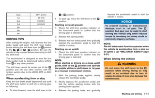
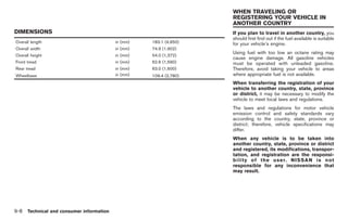
WHEELS AND TIRES
Road wheel
Type Size Offset in (mm)
Front: 20 6 9-1/2J 1.77 (45)
Aluminum
Rear: 20 6 10-1/2J 0.98 (25)
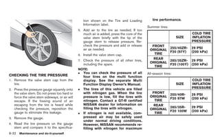
Tire
Type Size Pressure PSI (kPa) [Cold]
Front: 255/40ZRF20 (97Y)
Summer 29 (200)
Rear: 285/35ZRF20 (100Y)
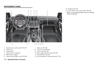
Front: 255/40RF20 97W
All-season 29 (200)
Rear: 285/35RF20 100W
Technical and consumer information 9-7
Model "R35-D" EDITED: 2008/ 4/ 18](https://image.slidesharecdn.com/2009-gt-r-120818113317-phpapp01/85/2009-GT-R-OWNER-S-MANUAL-291-320.jpg)


The Nissan GT-R, a supercar with a legacy dating back to 1964, has been upgraded for the 21st century, demonstrating its prowess with impressive track records and versatile performance across different road conditions. This owner’s manual provides crucial information about operating and maintaining the GT-R, emphasizing safe driving practices and vehicle modifications. Additional resources for customer care and warranty information are included, ensuring drivers are well-supported in their ownership experience.


![DESIGN AND FABRICATION OF THE IBM 90-90 SEAT BELT CLAMP KIA VEHICLE[1].pptx 2...](https://cdn.slidesharecdn.com/ss_thumbnails/designandfabricationoftheibm90-90seatbeltclampkiavehicle1-260116160442-70ff67fc-thumbnail.jpg?width=640&height=640&fit=bounds)


![[English Version]Maker-Ray Product Brochure V3 .pdf](https://cdn.slidesharecdn.com/ss_thumbnails/englishversionmaker-rayproductbrochurev3-260113094444-0156dbdc-thumbnail.jpg?width=640&height=640&fit=bounds)


