Functions of aPhysical layer:
• Line Configuration: It defines the way how two or more
devices can be connected physically.
• Data Transmission: It defines the transmission mode
whether it is simplex, half-duplex or full-duplex mode
between the two devices on the network.
• Topology: It defines the way how network devices are
arranged.
• Signals: It determines the type of the signal used for
transmitting the information.
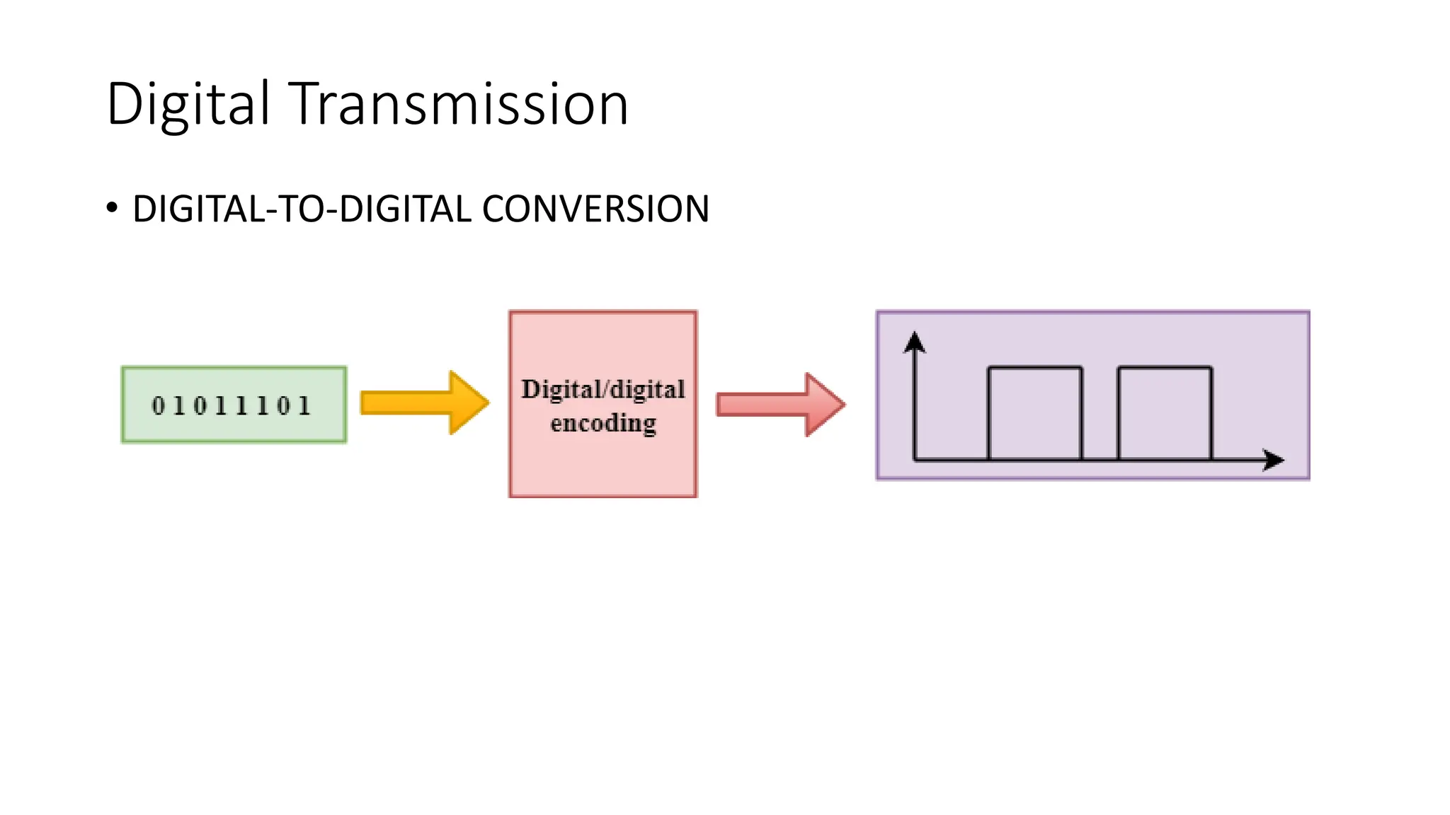
ANALOG-TO-DIGITAL CONVERSION
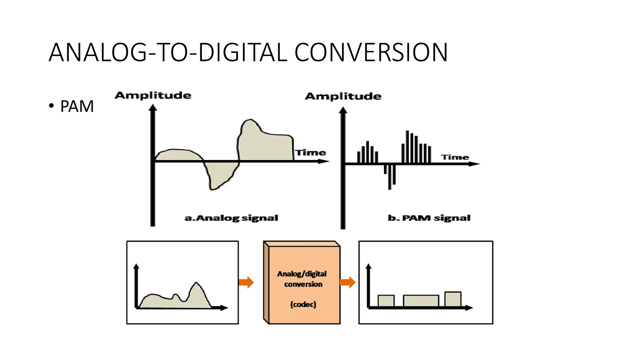
• Techniquesfor Analog-To-Digital Conversion : PAM
• PAM stands for pulse amplitude modulation.
• PAM is a technique used in analog-to-digital conversion.
• PAM technique takes an analog signal, samples it, and generates a
series of digital pulses.
• PAM technique is not useful in data communication as it translates
the original wave form into pulses, but these pulses are not digital.
• To make them digital, PAM technique is modified to PCM technique.
PCM - PulseCode Modulation.
• PCM technique is used to modify the pulses created by PAM to form
a digital signal.
• To achieve this, PCM quantizes PAM pulses. Quantization is a process
of assigning integral values in a specific range to sampled instances.
• PCM is made of four separate processes:
• PAM,
• quantization,
• binary encoding,
• and digital-to-digital encoding.
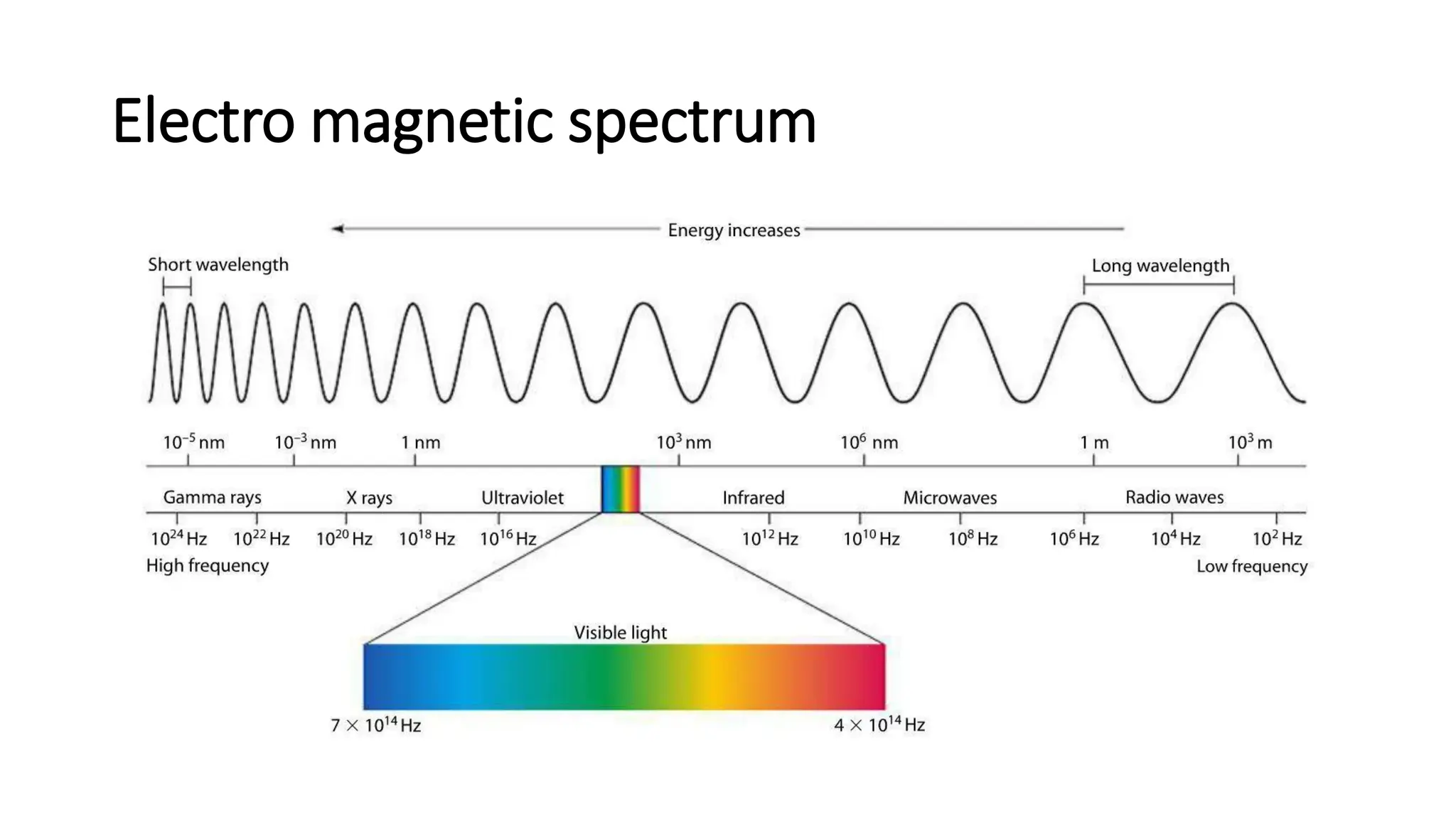
Electromagnetic spectrum
• Theelectromagnetic spectrum is the range of frequencies
(the spectrum) of electromagnetic radiation and their
respective wavelengths and photon energies.
12.
Electro magnetic spectrum
•The types of electromagnetic radiation are broadly classified into the
following classes (regions, bands or types):
• Gamma radiation
• X-ray radiation
• Ultraviolet radiation
• Visible radiation
• Infrared radiation
• Terahertz radiation
• Microwave radiation
• Radio waves
Uses of ElectromagneticWaves
Introduction
• Wavelength of the Electro Magnetic spectrum continually
changes
• high frequency = short wavelength
• high frequency = high energy
• high energy = more dangerous
16.
Uses of ElectroMagnetic Waves
• Radio Waves (communications)
• TV and FM radio (short wavelength)
• Direct line of sight with transmitter (do not diffract)
• Medium wavelength – travel further because they reflect from layers
in the atmosphere
17.
Uses of ElectroMagnetic Waves
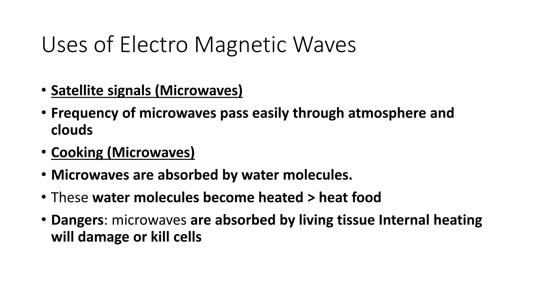
• Satellite signals (Microwaves)
• Frequency of microwaves pass easily through atmosphere and
clouds
• Cooking (Microwaves)
• Microwaves are absorbed by water molecules.
• These water molecules become heated > heat food
• Dangers: microwaves are absorbed by living tissue Internal heating
will damage or kill cells
18.
Uses of ElectroMagnetic Waves
• Infrared Radiation (remote controls, toasters)
• Any object that radiates heat radiates Infrared Radiation
• Infrared Radiation is absorbed by all materials and causes heating
• It is used for night vision and security cameras as Infrared Radiation
is visible in daytime or night-time
• Police use it to catch criminals, army use it to detect enemy
• Dangers: damage to cells (burns)
19.
Uses of ElectroMagnetic Waves
• Ultraviolet
• Dangers: over-exposure to UVA and B damages surface cells and eyes and can
cause cancer.
• Sun exposure for the skin is best restricted to before 11am and after 3pm in
the UK in summer months.
• Benefits:
• UVC is germicidal, destroying bacteria, viruses and moulds in the air, in water
and on surfaces.
• UV synthesises vitamin D in skin, controls the endocrine system and is a
painkiller.
• Used in state of the art air-handling units, personal air purifiers and
swimming pool technology and Water Purifier.
• Used to detect forged bank notes: they fluoresce in UV light; real bank notes
don’t.
• Used to identify items outside visible spectrum areas, known as 'black
lighting'.
20.
Uses of ElectroMagnetic Waves
• X-rays
• X-rays detect bone breaks
• X-rays pass through flesh but not dense material like bones
• Dangers: X-rays damage cells and cause cancers. Radiographer
precautions include wearing lead aprons and standing behind a lead screen
to minimise exposure
• Gamma Rays
• Gamma Rays cause and treat cancers
• In high doses, gamma can kill normal cells and cause cancers
• Gamma can be used to kill mutated cells though too.
21.
What is Transmissionmedia?
• Transmission media is a communication channel that carries the
information from the sender to the receiver. Data is transmitted
through the electromagnetic signals.
• The main functionality is to carry the information through a physical
path between transmitter and receiver in data communication.
• In a copper-based network, the bits in the form of electrical signals.
• In a fibre based network, the bits in the form of light pulses.
22.
Two Types ofTransmission media
• wired media : In wired media, medium characteristics are more
important whereas,
• wireless media. : in wireless media, signal characteristics are more
important.
• Properties of transmission media
• bandwidth,
• delay,
• cost and
• ease of installation and maintenance.
23.
Bandwidth
• Bandwidth: Bandwidthis the capacity of a wired or wireless
network communications link to transmit the maximum amount of
data from one point to another over a computer network in a given
amount of time -- usually one second. Synonymous with capacity,
bandwidth describes the data transfer rate.
• Bandwidth is not a measure of network speed -- a common
misconception.
• Bandwidth can be compared to the amount of water that can flow
through a water pipe.
24.
Bandwidth
• While bandwidthis traditionally expressed in bitsper second (bps,
Mbps, Gbps),.
• Bandwidth connections can be symmetrical, which means the data
capacity is the same in both directions to upload or download data,
or
• asymmetrical, which means download and upload capacity are not
equal. In asymmetrical connections, upload capacity is typically
smaller than download capacity.
Propagation Delay
• Incomputer networks, propagation delay is the amount of time it
takes for the head of the signal to travel from the sender to the
receiver.
• It can be computed as the ratio between the link length and the
propagation speed over the specific medium.
• Transmission Delay = Data size / bandwidth = (L/B) second.
27.
Guided Media
• Itis defined as the physical medium through which the signals are
transmitted. It is also known as Bounded media.
• Types Of Guided media:
1. Twisted pair
2. Coaxial Cable
3. Fibre Optic
28.
Twisted pair:
• isa physical media
• made up of a pair of cables twisted with each other.
• is cheap as compared to other transmission media.
• Installation is easy,
• is a lightweight cable.
• The frequency range for from 0 to 3.5KHz.
Unshielded Twisted Pair(UTP):
•An unshielded twisted pair is widely used in telecommunication.
• Commonly used types of UTP cabling are as follows:
• Category 1—Used for telephone communications. Not suitable for transmitting data.
• Category 2—Capable of transmitting data at speeds up to 4 Mbps.
• Category 3—Used in 10BASE-T networks. Can transmit data at speeds up to 10 Mbps.
• Category 4—Used in Token Ring networks. Can transmit data at speeds up to 16 Mbps.
• Category 5—Can transmit data at speeds up to 100 Mbps.
• Category 5e —Used in networks running at speeds up to 1000 Mbps (1 gigabit per
second [Gbps]).
• Category 6—Typically, Category 6 cable consists of four pairs of 24 American Wire
Gauge (AWG) copper wires. Category 6 cable is currently the fastest standard for UTP
31.
What is 10BASE-T
•10BASE-T, one of several physical media specified in
the IEEE 802.3 standard for Ethernet local area networks (LANs), is
ordinary telephone twisted pair wire. 10BASE-T supports Ethernet's
10 Mbps transmission speed. In addition to 10BASE-T, 10 megabit
Ethernet can be implemented with these media types:
• The "BASE" refers to baseband signalling, which means that only
Ethernet signals are carried on the medium.
• The "T" represents twisted-pair; the "F" represents fiber optic cable;
and the "2", "5", and "36" refer to the coaxial cable segment length
(the 185 meter length has been rounded up to "2" for 200).
32.
What is 10BASE-T
•10BASE-2 (Thin wire coaxial cable with a maximum segment length of
185 meters)
• 10BASE-5 (Thick wire coaxial cable with a maximum segment length
of 500 meters)
• 10BASE-F (optical fiber cable)
• 10BASE-36 (broadband coaxial cable carrying multiple baseband
channels for a maximum length of 3,600 meters)
33.
Unshielded Twisted Pair:
•Advantages Of Unshielded Twisted Pair:
• It is cheap.
• Installation is easy.
• It can be used for high-speed LAN.
• Disadvantage:
• This cable can only be used for shorter distances because
of attenuation.
34.
Shielded Twisted Pair(STP)
• A shielded twisted pair is a cable that contains the mesh surrounding
the wire that allows the higher transmission rate.
• Characteristics Of Shielded Twisted Pair:
• The cost is not very high and not very low.
• An installation of STP is easy.
• It has higher capacity as compared to unshielded twisted pair cable.
• It has a higher attenuation.
• It is shielded that provides the higher data transmission rate.
• Disadvantages
• It is more expensive as compared to UTP and coaxial cable.
• It has a higher attenuation rate.
35.
UTP Vs STP
•The speed of both types of cable is usually satisfactory for local-area
distances.
• These are the least-expensive media for data communication. UTP is
less expensive than STP.
36.
Coaxial Cable
• Itis very commonly used transmission media, for example, TV wire
is usually a coaxial cable.
• It contains two conductors parallel to each other.
• It has a higher frequency as compared to Twisted pair cable.
• The inner conductor cable is made up of copper, and the outer
conductor is made up of copper mesh these are separated by non-
conductive.
• The inner (middle) core is responsible for the data transferring
whereas the copper mesh prevents from the EMI(Electromagnetic
interference).
Coaxial cable isof two types:
1. Baseband transmission: It is defined as the process of transmitting
a single signal at high speed.
2. Broadband transmission: It is defined as the process of transmitting
multiple signals simultaneously.
• Advantages Of Coaxial cable:
• The data can be transmitted at high speed.
• It has better shielding as compared to twisted pair cable.
• It provides higher bandwidth.
• Disadvantages Of Coaxial cable:
• It is more expensive as compared to twisted pair cable.
• If any fault occurs in the cable causes the failure in the entire network.
39.
Features of coaxialcables:
• Speed and throughput—10 to 100 Mbps
• Average cost per node—Inexpensive
• Media and connector size—Medium
• Maximum cable length—500 m (medium)
40.
Know more aboutthese
• Plenum Cable?
• Types of Coaxial Cable?
41.
Fibre Optic
• Fibreoptic is a cable that holds the optical fibres coated in plastic
that are used to send the data by pulses of light.
• The plastic coating protects the optical fibres from heat, cold,
electromagnetic interference from other types of wiring.
• Fibre optics provide faster data transmission than copper wires.
42.
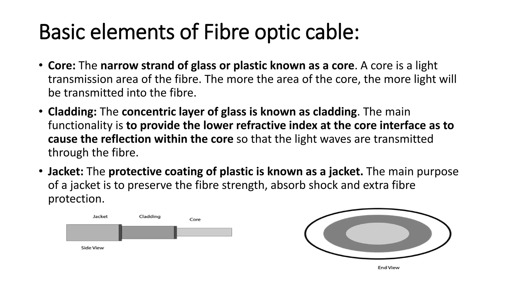
Basic elements ofFibre optic cable:
• Core: The narrow strand of glass or plastic known as a core. A core is a light
transmission area of the fibre. The more the area of the core, the more light will
be transmitted into the fibre.
• Cladding: The concentric layer of glass is known as cladding. The main
functionality is to provide the lower refractive index at the core interface as to
cause the reflection within the core so that the light waves are transmitted
through the fibre.
• Jacket: The protective coating of plastic is known as a jacket. The main purpose
of a jacket is to preserve the fibre strength, absorb shock and extra fibre
protection.
43.
Advantages of FibreOptic:
• Greater Bandwidth: provides more bandwidth and carries more data
as compared to copper cable.
• Faster speed: carries the data in the form of light which makes it to
carry the signals at a higher speed.
• Longer distances: carries the data to a longer distance ( 0 to
1000Kms).
• Better reliability: is immune to any temperature changes.
• Thinner and Sturdier: is thinner and lighter in weight so it can
withstand more pull pressure than copper cable.
44.
Un Guided Transmission
(wirelesstransmission)
• It transmits the electromagnetic waves without using any physical
medium. Therefore it is also known as wireless transmission.
• Space is the media through which the electromagnetic energy can
flow easily.
• Categories:
1. Radio waves
2. Microwaves
3. Infrared
45.
Radio waves
• Radiowaves are the electromagnetic waves that are transmitted in
all the directions of free space.
• Are omnidirectional, i.e., the signals are propagated in all the
directions.
• Radio waves have frequencies as high as 300 gigahertz (GHz) to as
low as 30 hertz (Hz). At 300 GHz, the corresponding wavelength is 1
mm, and at 30 Hz is 10,000 km.
• In the case of radio waves, the sending and receiving antenna are not
aligned.
• An example of the radio wave is FM radio.
Radio Wave
• ApplicationsOf Radio waves:
• is useful for multicasting when there is one sender and many
receivers.
• An FM radio, television, cordless phones are examples of a radio
wave.
• Advantages Of Radio transmission:
• Radio transmission is mainly used for wide area networks and
mobile cellular phones.
• They cover a large area, and can penetrate the walls.
• Radio transmission provides a higher transmission rate.
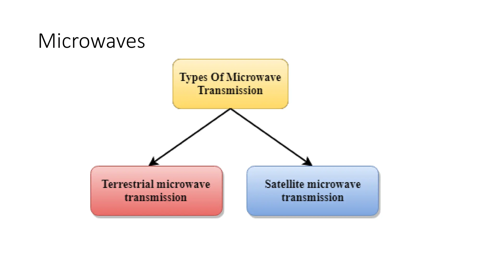
Terrestrial Microwave Transmission
•Terrestrial Microwave transmission is a technology that transmits the
focused beam of a radio signal from one ground-based microwave
transmission antenna to another.
• frequency in the range from 1GHz to 1000 GHz.
• unidirectional as the sending and receiving antenna is to be aligned,
i.e., the waves sent by the sending antenna are narrowly focussed.
• antennas are mounted on the towers to send a beam to another
antenna which is few kms away.
• It works on the line of sight transmission, i.e., the antennas mounted
on the towers are the direct sight of each other.
50.
Terrestrial Microwave Transmission
•Characteristics of Terrestrial Microwave:
• Frequency range: from 4-6 GHz to 21-23 GHz.
• Bandwidth: bandwidth from 1 to 10 Mbps.
• Short distance: It is inexpensive for short distance.
• Long distance: It is expensive as it requires a higher tower for a longer
distance.
• Attenuation: Attenuation means loss of signal. It is affected by
environmental conditions and antenna size.
51.
Terrestrial Microwave Transmission
•Advantages Of Microwave:
• transmission is cheaper than using cables.
• it does require small area for the installation.
• provides an easy communication in terrains.
• Communication over oceans can be achieved by using microwave
transmission.
• Disadvantages of Microwave transmission:
• Eavesdropping: An eavesdropping creates insecure communication. Any
malicious user can catch the signal in the air by using there own antenna.
• Out of phase signal: A signal can be moved out of phase by using microwave
transmission.
• Susceptible to weather condition: is susceptible to weather condition.
• Bandwidth limited: Allocation of bandwidth is limited.
52.
Satellite Microwave Communication
•A satellite is a physical object that revolves around the earth at a
known height.
• Satellite communication is more reliable one can communicate with
any point on the globe by using satellite communication.
• How Does Satellite work? : The satellite accepts the signal that is
transmitted from the earth station, and it amplifies the signal. The
amplified signal is retransmitted to another earth station.
53.
Satellite Microwave Communication
•Advantages Of Satellite Microwave Communication:
• The coverage area more than the terrestrial microwave.
• The transmission cost of the satellite is independent of the
distance from the centre of the coverage area.
• It is used in mobile and wireless communication applications.
• It is easy to install. Applications are : weather forecasting,
radio/TV signal broadcasting, mobile communication, etc.
54.
Satellite Microwave Communication
•Disadvantages Of Satellite Microwave Communication:
• Satellite designing and development requires more time and
higher cost.
• The Satellite needs to be monitored and controlled on regular
periods so that it remains in orbit.
• The life of the satellite is about 12-15 years. Due to this reason,
another launch of the satellite has to be made.
55.
Infrared
• An infraredtransmission is a wireless technology used for
communication over short ranges.
• The frequency of the infrared in the range from 300 GHz to
400 THz.
• It is used for short-range communication such as data
transfer between two cell phones, TV remote operation,
data transfer between a computer and cell phone resides in
the same closed area.
56.
Infrared
• Characteristics OfInfrared:
• It supports high bandwidth so more data at higher data
rate.
• Infrared waves cannot penetrate the walls. Therefore,
the infrared communication in one room cannot be
interrupted by the nearby rooms this increases security.
• is unreliable outside the building because the sun rays
will interfere with the infrared waves.
57.
Bluetooth
• Bluetooth isa wireless technology standard
• for exchanging data between fixed and
• mobile devices over short distances using short-wavelength
• UHF radio waves in the industrial, scientific and medical
radio bands, from 2.400 to 2.485 GHz, and building personal
area networks.
58.
Bluetooth
• Frequency: 2.45GHz
• Developed by: Bluetooth Special Interest Group
• Physical range: Typically less than 10 m (33 ft), up to 100 m
(330 ft); Bluetooth 5.0: 40–400 m (100–1,000 ft)
• Compatible hardware: Personal computers; Smartphones;
Gaming consoles; Audio devices
59.
Bluetooth
Ranges of Bluetoothdevices by class
Class
Max. permitted power Typ. range[2]
(m)
(mW) (dBm)
1 100 20 ~100
1.5
(BT 5 Vol 6 Part
A Sect 3)
10 10 ~20
2 2.5 4 ~10
3 1 0 ~1
4 0.5 −3 ~0.5
60.
1G: Voice Only
•Remember Analog phones back in the day? Cell phones
began with 1G technology in the 1980s. 1G is the first
generation of wireless cellular technology. 1G supports
voice only calls.
• 1G is Analog technology, and the phones using it had poor
battery life and voice quality, little security, and were prone
to dropped calls.
• The maximum speed of 1G technology is 2.4 Kbps.
61.
2G: SMS andMMS
• 2G started place in Finland in 1991 on GSM networks and effectively
took cell phones from analog to digital communications.
• The 2G telephone technology introduced call and text encryption,
along with data services such as SMS, picture messages, and MMS.
• The maximum speed of 2G with General Packet Radio Service (GPRS)
is 50 Kbps. The speed is 1 Mbps with Enhanced Data Rates for GSM
Evolution (EDGE).
62.
2.5G and 2.75G:Data, Finally
• 2.5G and 2.75G were interim standards that bridged the gap to make
data transmission — slow data transmission — possible.
• 2.5G introduced a new packet-switching technique
• This led to 2.75G, which provided a theoretical threefold speed
increase. AT&T was the first GSM network to support 2.75G with
EDGE in the U.S.
• 2.5G and 2.75G were not defined formally as wireless standards.
They served mostly as marketing tools to promote new cell phone
features to the public.
63.
3G: More Data,Video Calling, and Mobile Internet
• 3G networks in 1998 ushered in faster data-transmission
speeds, such as for video calling and mobile internet access.
The term "mobile broadband" was first applied to 3G
cellular technology.
• Like 2G, 3G evolved into the much faster 3.5G and 3.75G as
more features were introduced to bring about 4G.
• The maximum speed of 3G is estimated to be around 2
Mbps for non-moving devices and 384 Kbps in moving
vehicles.
64.
4G: The CurrentStandard
• Released in 2008,
• 4G supports mobile web access, gaming services, HD mobile TV,
video conferencing, 3D TV, and other features that demand
high speeds.
• The max speed when the device is moving is 100 Mbps. The speed is
1 Gbps for low-mobility communication such as when the caller is
stationary or walking.
65.
5G: Coming Soon
•5G is a not-yet-implemented wireless technology that's intended to
improve on 4G.
• 5G promises significantly faster data rates, higher connection density,
much lower latency, and energy savings, among other improvements.
• The anticipated theoretical speed of 5G connections is up to 20 Gbps
per second.
66.
Switching
• When auser accesses the internet or another computer network
outside their immediate location, messages are sent through the
network of transmission media.
• This technique of transferring the information from one computer
network to another network is known as switching.
• Switching is transparent to the user and does not require any
configuration in the home network.
67.
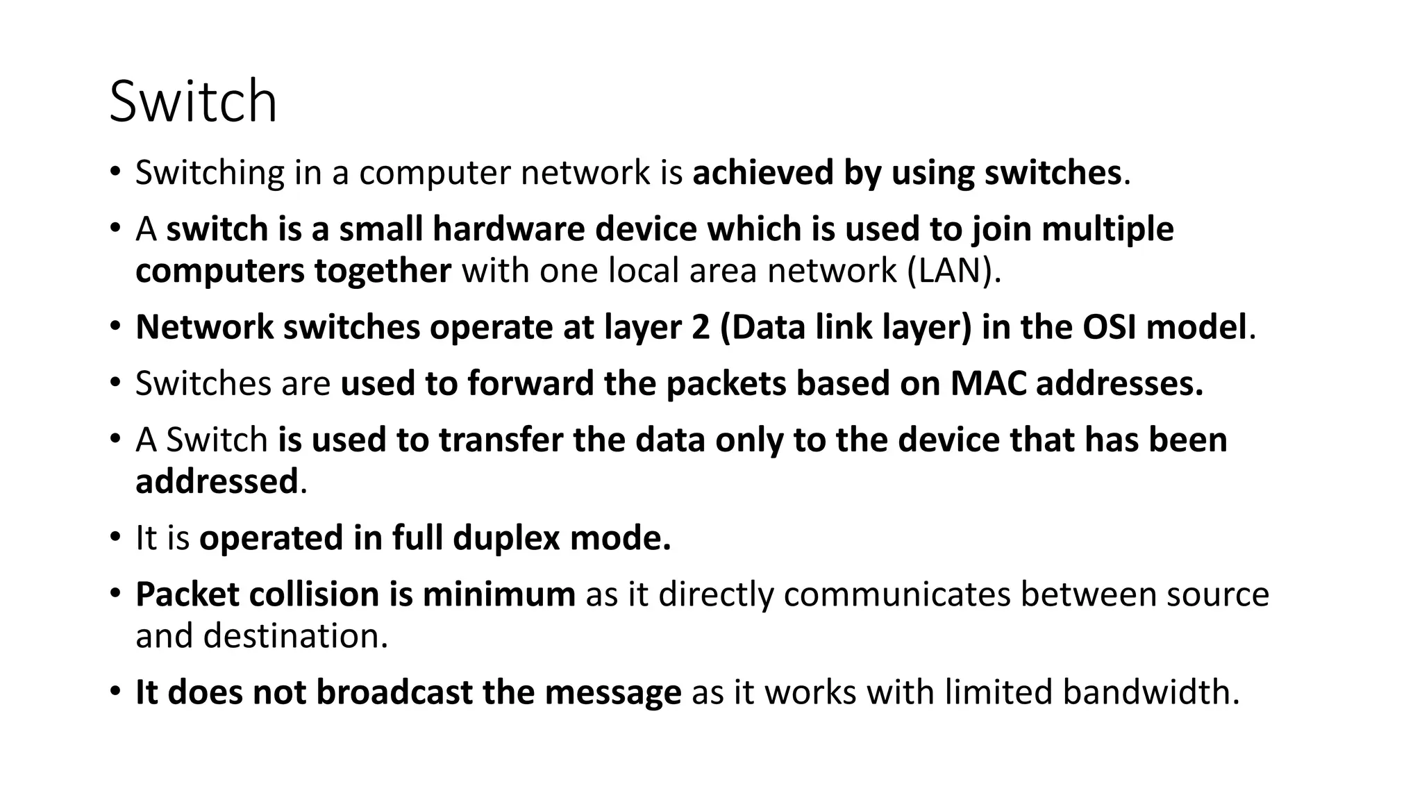
Switch
• Switching ina computer network is achieved by using switches.
• A switch is a small hardware device which is used to join multiple
computers together with one local area network (LAN).
• Network switches operate at layer 2 (Data link layer) in the OSI model.
• Switches are used to forward the packets based on MAC addresses.
• A Switch is used to transfer the data only to the device that has been
addressed.
• It is operated in full duplex mode.
• Packet collision is minimum as it directly communicates between source
and destination.
• It does not broadcast the message as it works with limited bandwidth.
68.
Switching
• Why isSwitching Concept required?
• Switching concept is developed because of the following reasons:
• Bandwidth: The switching techniques are used for the effective
utilization of the bandwidth of a network.
• Collision: To overcome this problem, switching technology is
implemented so that packets do not collide with each other.
69.
Switching
• Advantages ofSwitching:
• increases the bandwidth of the network.
• It reduces the workload on individual PCs
• It increases the overall performance of the network by reducing the traffic
on the network.
• There will be less frame collision as switch creates the collision domain for
each connection.
• Disadvantages of Switching:
• A Switch is more expensive than network bridges.
• A Switch cannot determine the network connectivity issues easily.
• Proper designing and configuration of the switch are required to handle
multicast packets.
70.
Switching Modes
• Thelayer 2 switches are used for transmitting the data on the data
link layer, and it also performs error checking on transmitted and
received frames.
• The layer 2 switches forward the packets with the help of MAC
address.
• Different modes are used for forwarding the packets known
as Switching modes.
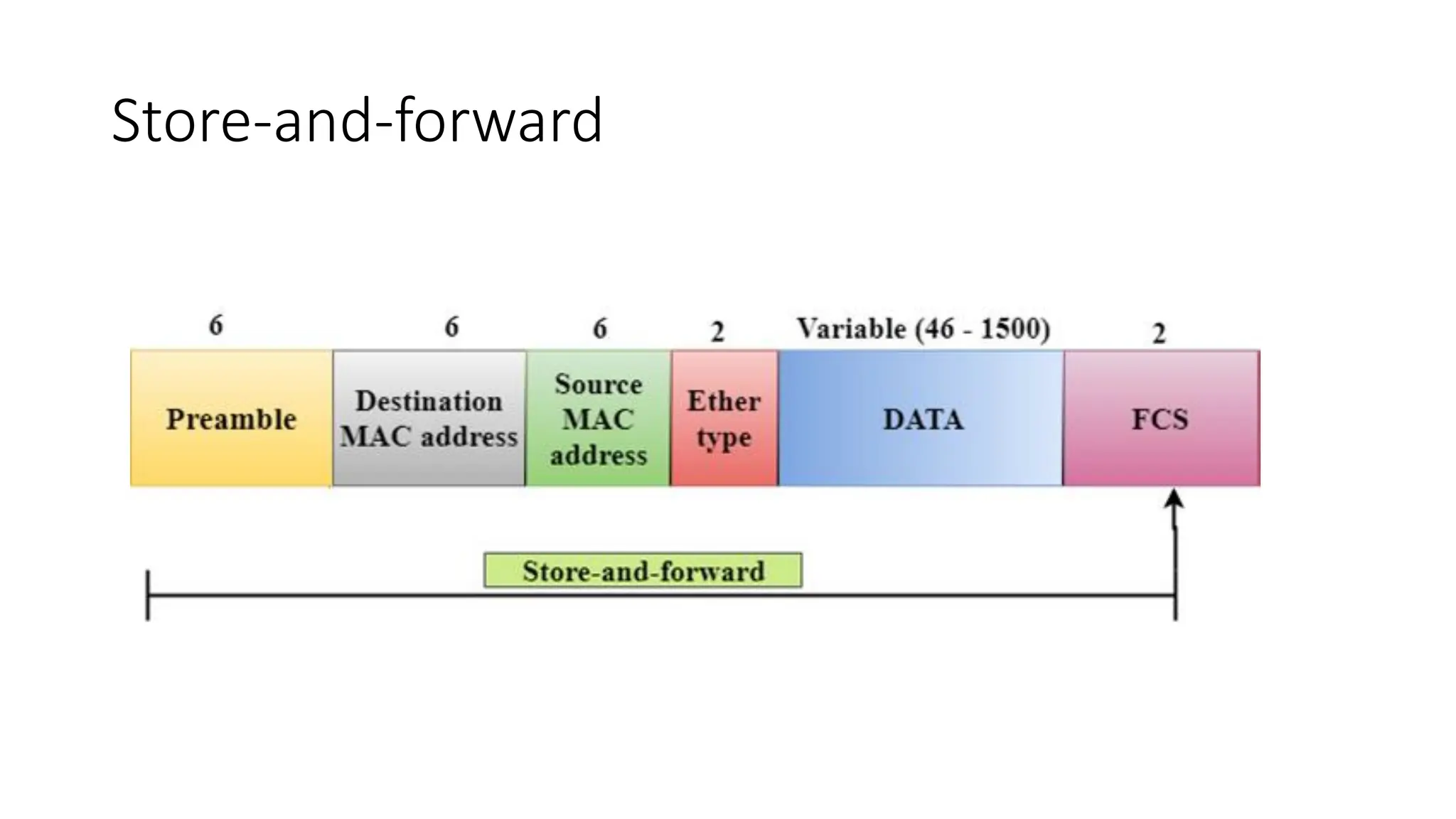
• In switching mode, Different parts of a frame are recognized. The
frame consists of several parts such as preamble, destination MAC
address, source MAC address, user's data, FCS.
71.
Frame
• A frameis a digital data transmission unit in computer networking.
• In packet switched systems, a frame is a simple container for a
single network packet.
Store-and-forward
• Store-and-forward isa technique in which the intermediate nodes
store the received frame and then check for errors before
forwarding the packets to the next node.
• The layer 2 switch waits until the entire frame has received. On
receiving the entire frame, switch store the frame into the switch
buffer memory. This process is known as storing the frame.
• When the frame is stored, then the frame is checked for the errors. If
any error found, the message is discarded otherwise the message is
forwarded to the next node. This process is known as forwarding the
frame.
76.
Store-and-forward
• CRC (CyclicRedundancy Check) technique is implemented that uses
a number of bits to check for the errors on the received frame.
• The store-and-forward technique ensures a high level of security as
the destination network will not be affected by the corrupted
frames.
• Store-and-forward switches are highly reliable as it does not forward
the collided frames.
Cut-through Switching
• Cut-throughswitching is a technique in which the switch forwards
the packets after the destination address has been identified
without waiting for the entire frame to be received.
• Once the frame is received, it checks the first six bytes of the frame
following the preamble, the switch checks the destination in the
switching table to determine the outgoing interface port, and
forwards the frame to the destination.
• It has low latency rate as the switch does not wait for the entire
frame to be received before sending the packets to the destination.
79.
Cut-through Switching
• Ithas no error checking technique. Therefore, the errors can be sent
with or without errors to the receiver.
• A Cut-through switching technique has low wait time as it forwards
the packets as soon as it identifies the destination MAC address.
• In this technique, collision is not detected, if frames have collided will
also be forwarded.
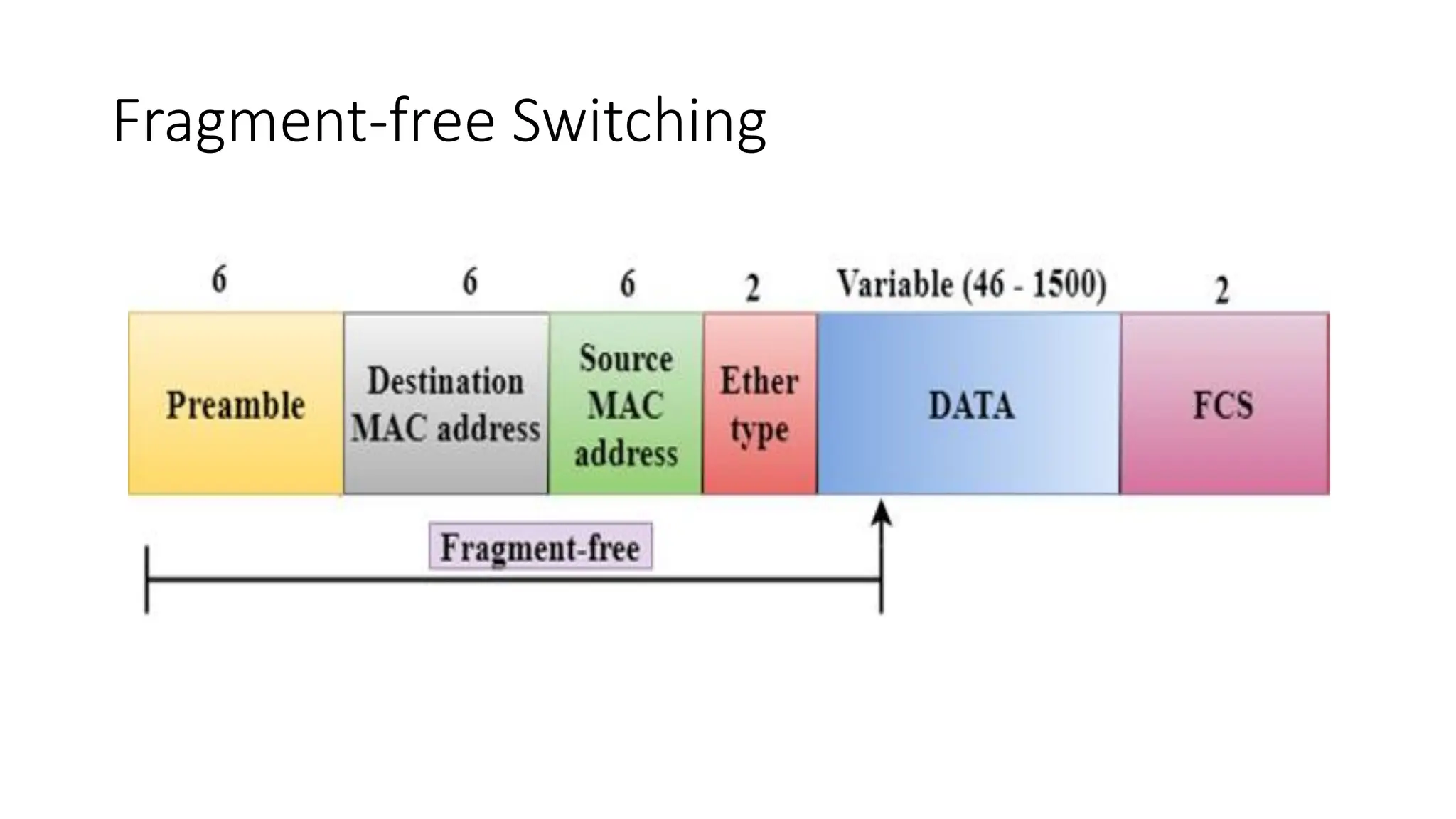
Fragment-free Switching
• AFragment-free switching is an advanced technique of the Cut-through
Switching.
• A Fragment-free switching is a technique that reads at least 64 bytes of a
frame before forwarding to the next node to provide the error-free
transmission.
• It combines the speed of Cut-through Switching with the error checking
functionality.
• This technique checks the 64 bytes of the ethernet frame where
addressing information is available.
• A collision is detected within 64 bytes of the frame, the frames which are
collided will not be forwarded further.
82.
Switching techniques
• Inlarge networks, there can be multiple paths from sender to
receiver. The switching technique will decide the best route for data
transmission.
• Switching technique is used to connect the systems for making one-
to-one communication.
• Classification Of Switching Techniques
1. Circuit Switching
2. Message Switching
3. Packet Switching
Circuit Switching
• Itis a switching technique that establishes a dedicated path between
sender and receiver.
• In this, once the connection is established then the dedicated path will
remain to exist until the connection is terminated.
• It operates in a similar way as the telephone works.
• A complete end-to-end path must exist before the communication takes
place.
• In case of circuit switching technique, when any user wants to send the
data, voice, video, a request signal is sent to the receiver then the receiver
sends back the acknowledgment to ensure the availability of the
dedicated path. After receiving the acknowledgment, dedicated path
transfers the data.
85.
Circuit Switching
• Communicationthrough circuit switching has 3 phases:
• Circuit establishment
• Data transfer
• Circuit Disconnect
Circuit Switching
• SpaceDivision Switches: is a circuit switching technology in which a
single transmission path is accomplished in a switch by using a
physically separate set of cross points.
• It can be achieved by using crossbar switch. A crossbar switch is a
metallic cross point or semiconductor gate that can be enabled or
disabled by a control unit.
• The Crossbar switch is made by using the semiconductor. For
example, Xilinx crossbar switch using FPGAs.
• These are high speed, high capacity, and non blocking switches.
Circuit Switching
• SpaceDivision Switches can be categorized in two ways:
• Crossbar Switch
• Multistage Switch
• Crossbar Switch : The Crossbar switch is a switch that has n input
lines and n output lines. The crossbar switch has n2 intersection
points known as cross points.
• Disadvantage of Crossbar switch:
• The number of cross points increases as the number of stations is
increased. Therefore, it becomes very expensive for a large switch.
The solution to this is to use a multistage switch.
90.
Circuit Switching
• MultistageSwitch : Multistage Switch is made by splitting the
crossbar switch into the smaller units and then interconnecting
them.
• It reduces the number of crosspoints.
• If one path fails, then there will be an availability of another path.
Circuit Switching
• AdvantagesOf Circuit Switching:
• In the case of Circuit Switching technique, the communication
channel is dedicated.
• It has fixed bandwidth.
93.
Circuit Switching
• DisadvantagesOf Circuit Switching:
• Once the dedicated path is established, the only delay occurs in the
speed of data transmission.
• It takes a long time to establish a connection approx 10 seconds
during which no data can be transmitted.
• It is more expensive than other switching techniques as a dedicated
path is required for each connection.
• It is inefficient to use because once the path is established and no
data is transferred, then the capacity of the path is wasted.
• In this case, the connection is dedicated therefore no other data can
be transferred even if the channel is free.
94.
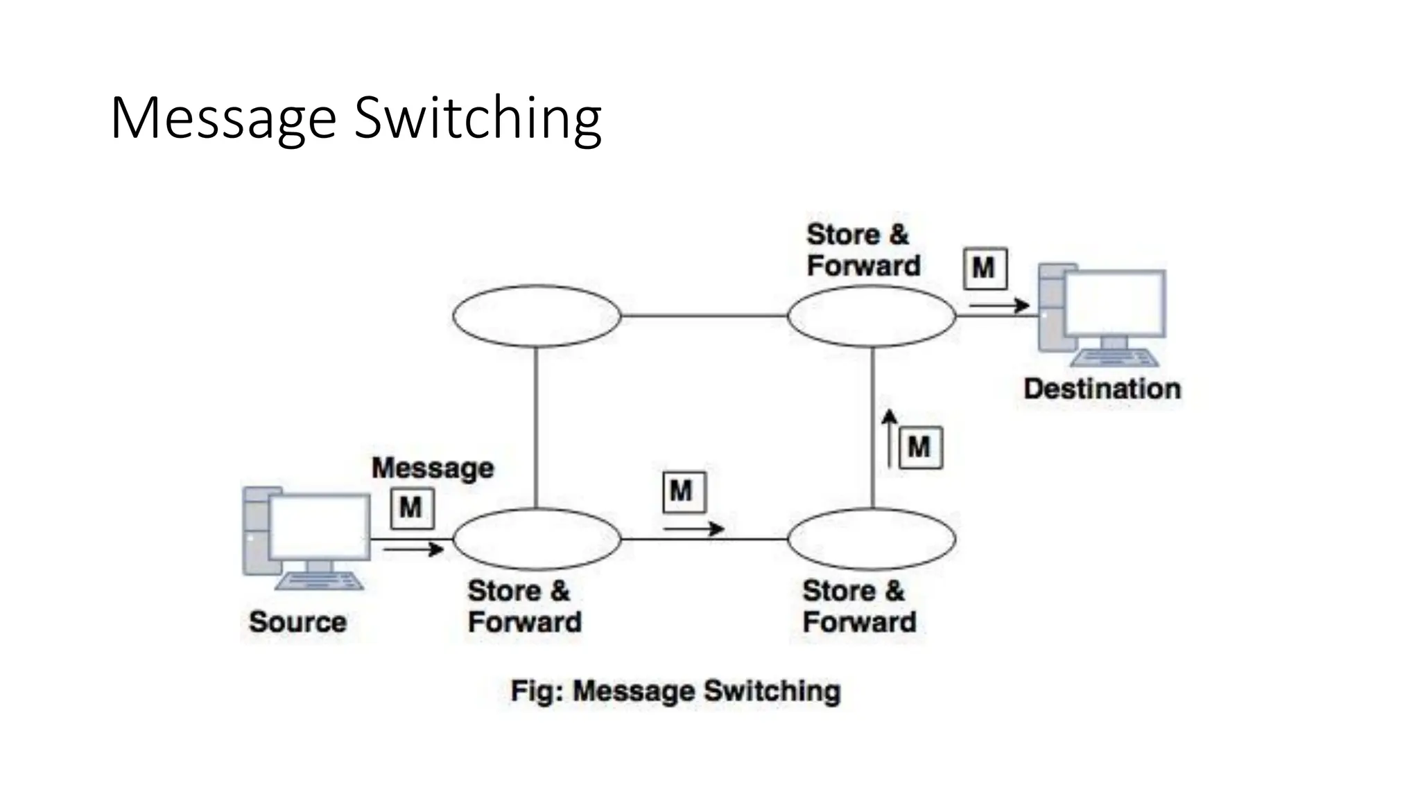
Message Switching
• MessageSwitching : is a switching technique in which a message is
transferred as a complete unit and routed through intermediate nodes at
which it is stored and forwarded.
• In this there is no establishment of a dedicated path between the sender
and receiver.
• The destination address is appended to the message. It provides a
dynamic routing as the message is routed through the intermediate
nodes based on the information available in the message.
• Message switches are programmed in such a way so that they can provide
the most efficient routes.
• Each and every node stores the entire message and then forward it to the
next node. This type of network is known as store and forward network.
• Message switching treats each message as an independent entity.
Message Switching
• AdvantagesOf Message Switching
• Data channels are shared among the communicating devices that
improve the efficiency of using available bandwidth.
• Traffic congestion can be reduced because the message is
temporarily stored in the nodes.
• Message priority can be used to manage the network.
• The size of the message which is sent over the network can be
varied. Therefore, it supports the data of unlimited size.
98.
Message Switching
• DisadvantagesOf Message Switching
• The message switches must be equipped with sufficient storage to
enable them to store the messages until the message is forwarded.
• The Long delay can occur due to the storing and forwarding facility
provided by the message switching technique.
99.
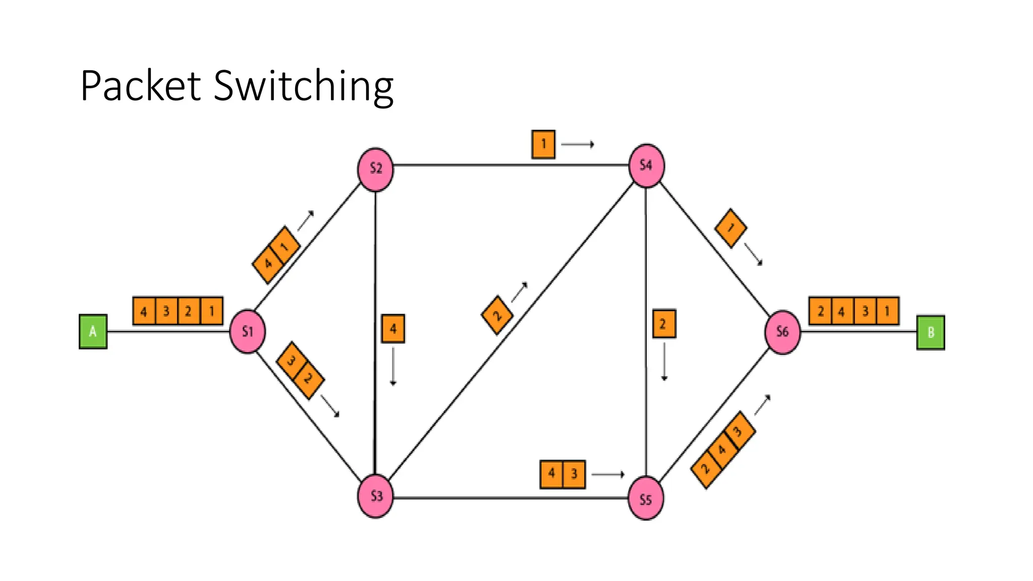
Packet Switching
• Thepacket switching : is a switching technique in which the message
is sent in one go, but it is divided into smaller pieces, and they are
sent individually.
• The message splits into smaller pieces known as packets and packets
are given a unique number to identify their order at the receiving
end.
• Every packet contains some information in its headers such as
source address, destination address and sequence number.
100.
Packet Switching
• Packetswill travel across the network, taking the shortest path as
possible.
• All the packets are reassembled at the receiving end in correct
order.
• If any packet is missing or corrupted, then the message will be sent
to resend the message.
• If the correct order of the packets is reached, then the
acknowledgment message will be sent.
Packet Switching:
• ApproachesOf Packet Switching: There are two approaches to Packet
Switching:
• Datagram Packet switching:
• In this packet is known as a datagram, is considered as an independent entity.
Each packet contains the information about the destination and switch uses
this information to forward the packet to the correct destination.
• The packets are reassembled at the receiving end in correct order.
• In Datagram Packet Switching technique, the path is not fixed.
• Intermediate nodes take the routing decisions to forward the packets.
• Datagram Packet Switching is also known as connectionless switching.
103.
Packet Switching:
• VirtualCircuit Switching
• Virtual Circuit Switching is also known as connection-oriented switching.
• In the case of Virtual circuit switching, a pre planned route is established
before the messages are sent.
• Call request and call accept packets are used to establish the connection
between sender and receiver.
• In this case, the path is fixed for the duration of a logical connection.
Packet Switching
• Inthe above diagram, A and B are the sender and receiver
respectively. 1 and 2 are the nodes.
• Call request and call accept packets are used to establish a connection
between the sender and receiver.
• When a route is established, data will be transferred.
• After transmission of data, an acknowledgment signal is sent by the
receiver that the message has been received.
• If the user wants to terminate the connection, a clear signal is sent for
the termination.
106.
Differences b/w Datagramapproach and
Virtual Circuit approach
Datagram approach Virtual Circuit approach
Node takes routing
decisions to forward the
packets.
Node does not take any routing
decision.
Congestion cannot occur
as all the packets travel in
different directions.
Congestion can occur when the
node is busy, and it does not allow
other packets to pass through.
It is more flexible as all the
packets are treated as an
independent entity.
It is not very flexible.
107.
Packet Switching:
• AdvantagesOf Packet Switching:
• Cost-effective: In packet switching technique, switching devices do not
require massive secondary storage to store the packets, so cost is minimized
to some extent. Therefore, we can say that the packet switching technique is
a cost-effective technique.
• Reliable: If any node is busy, then the packets can be rerouted. This ensures
that the Packet Switching technique provides reliable communication.
• Efficient: Packet Switching is an efficient technique. It does not require any
established path prior to the transmission, and many users can use the same
communication channel simultaneously, hence makes use of available
bandwidth very efficiently.
108.
Packet Switching:
• DisadvantagesOf Packet Switching:
• Not suited for those applications that require low delay and high-
quality services.
• The protocols used in a packet switching technique are very
complex and requires high implementation cost.
• If the network is overloaded or corrupted, then it requires
retransmission of lost packets.
• It can also lead to the loss of critical information if errors are nor
recovered.
109.
What is Multiplexing?
•Multiplexing is a technique used to combine and send the multiple data
streams over a single medium.
• The process of combining the data streams is known as multiplexing
and hardware used for multiplexing is known as a multiplexer.
• Multiplexing is achieved by using a device called Multiplexer (MUX)
that combines n input lines to generate a single output line.
Multiplexing follows many-to-one, i.e., n input lines and one output
line.
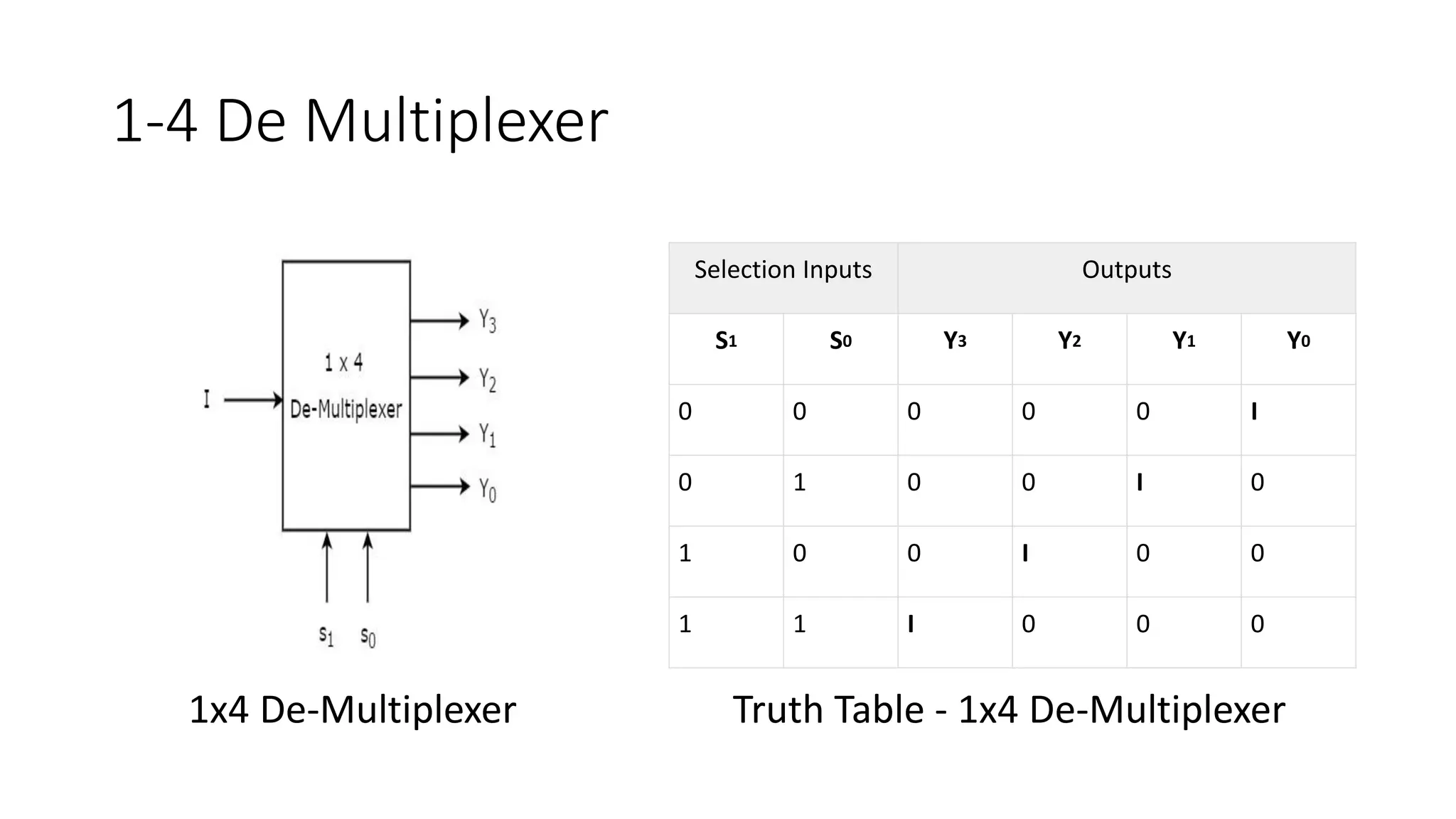
What is Demultiplexing?
• De multiplexing is achieved by using a device called De multiplexer
(DEMUX) available at the receiving end. DEMUX separates a signal into
its component signals (one input and n outputs). Therefore, we can say
that de multiplexing follows the one-to-many approach.
112.
1-4 De Multiplexer
SelectionInputs Outputs
S1 S0 Y3 Y2 Y1 Y0
0 0 0 0 0 I
0 1 0 0 I 0
1 0 0 I 0 0
1 1 I 0 0 0
1x4 De-Multiplexer Truth Table - 1x4 De-Multiplexer


![Unshielded Twisted Pair(UTP):
• An unshielded twisted pair is widely used in telecommunication.
• Commonly used types of UTP cabling are as follows:
• Category 1—Used for telephone communications. Not suitable for transmitting data.
• Category 2—Capable of transmitting data at speeds up to 4 Mbps.
• Category 3—Used in 10BASE-T networks. Can transmit data at speeds up to 10 Mbps.
• Category 4—Used in Token Ring networks. Can transmit data at speeds up to 16 Mbps.
• Category 5—Can transmit data at speeds up to 100 Mbps.
• Category 5e —Used in networks running at speeds up to 1000 Mbps (1 gigabit per
second [Gbps]).
• Category 6—Typically, Category 6 cable consists of four pairs of 24 American Wire
Gauge (AWG) copper wires. Category 6 cable is currently the fastest standard for UTP](https://image.slidesharecdn.com/2-physicallayer06-250818151848-eaec3232/75/2-Physical-Layer-06-pdfgshshshbsbshshshhs-30-2048.jpg)


![Bluetooth
Ranges of Bluetooth devices by class
Class
Max. permitted power Typ. range[2]
(m)
(mW) (dBm)
1 100 20 ~100
1.5
(BT 5 Vol 6 Part
A Sect 3)
10 10 ~20
2 2.5 4 ~10
3 1 0 ~1
4 0.5 −3 ~0.5](https://image.slidesharecdn.com/2-physicallayer06-250818151848-eaec3232/75/2-Physical-Layer-06-pdfgshshshbsbshshshhs-59-2048.jpg)