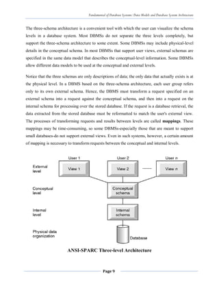
The document discusses database system architecture and data models. It introduces the three schema architecture which separates the conceptual, logical and internal schemas. This provides logical data independence where the conceptual schema can change without affecting external schemas or applications. It also discusses various data models like hierarchical, network, relational and object-oriented models. Key aspects of each model like structure, relationships and operations are summarized.
![Fundamental of Database Systems: Data Models and Database System Architecture
Page 10
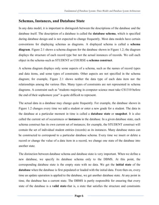
External View 1
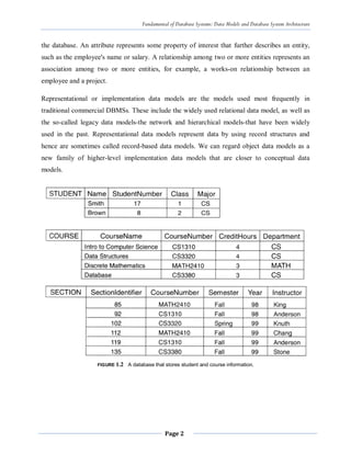
Staff_No FName Salary
External View 2
FName DOB
Conceptual Level
Staff_No FName LName DOB Salary Branch_No
Internal Level
struct STAFF{
int Staff_No;
int Branch_No;
char FName[15];
char LName[15];
struct DOB;
float salary;
}
Fig. Differences between Three Levels of ANSI-SPARC Architecture
The ANSI-SPARC Architecture Defines DBMS schemas at three levels:
Internal schema
o at the internal level to describe physical storage structures and access paths.
Typically uses a physical data model.
Conceptual schema
o at the conceptual level to describe the structure and constraints for the whole
database for a community of users. Uses a conceptual or an implementation data
model.
External schemas
o at the external level to describe the various user views. Usually uses the same data
model as the conceptual level.](https://image.slidesharecdn.com/2-230504131445-f99e473f/85/2-Chapter-Two-pdf-10-320.jpg)
![chapter 2-DATABASE SYSTEM CONCEPTS AND architecture [Autosaved].pdf](https://cdn.slidesharecdn.com/ss_thumbnails/chapter2-databasesystemconceptsandarchitectureautosaved-230512145134-613f7180-thumbnail.jpg?width=640&height=640&fit=bounds)


![Database System Concepts AND architecture [Autosaved].pptx](https://cdn.slidesharecdn.com/ss_thumbnails/databasesystemconceptsandarchitectureautosaved-230817173311-be7f8590-thumbnail.jpg?width=640&height=640&fit=bounds)