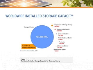
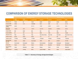
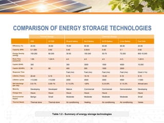
The document discusses various energy storage techniques and provides comparisons between them. It describes characteristics like efficiency, capacity, energy density, response time, lifetime, and costs for different storage methods including mechanical storage, electrical storage, thermal storage, and chemical storage technologies. These include pumped hydro, flywheels, capacitors, batteries, fuel cells, and thermal options like cryogenic, latent heat, and sensible heat systems. Comparisons are made between technologies based on these characteristics and their suitability for different applications. The largest existing pumped hydro plant is highlighted as an example system.


![The Bath County Pumped Storage Station is a
pumped storage hydroelectric power plant, which is
described as the “largest battery in the world”, with a
generation capacity of 3,003 MW[3] The station is
located in the northern corner of Bath County,
Virginia, on the southeast side of the Eastern
Continental Divide, which forms this section of the
border between Virginia and West Virginia. The
station consists of two reservoirs separated by about
1,260 feet (380 m) in elevation.
It is the largest pumped-storage power station in the
world. Construction on the power station, with an
original capacity of 2,100 megawatts (2,800,000
hp), began in March 1977 and was completed in
December 1985 at a cost of $1.6 billion, Voith-
Siemens upgraded the six turbines between 2004
and 2009, increasing power generation to 500.5
MW and pumping power to 480 megawatts
(640,000 hp) for each turbine.
MECHANICAL ENERGY
Technology Type
Open-loop Pumped
Hydro Storage (Time Shift)
Rated Power in kW
3,003,000
Duration at Rated Power
10:18.00](https://image.slidesharecdn.com/12629131-231105095923-451a79de/85/12629131-ppt-6-320.jpg)
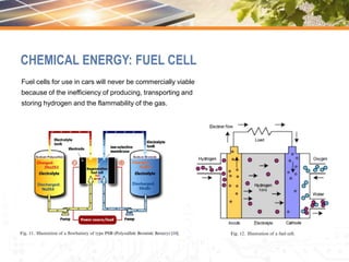
![A fuel cell is a device that converts the chemical
energy from a fuel into electricity through a
chemical reaction of positively charged hydrogen
ions with oxygen or another oxidizing agent. Fuel
cells are different from batteries in that they
require a continuous source of fuel and oxygen or
air to sustain the chemical reaction, whereas in a
battery the chemicals present in the battery react
with each other to generate an electromotive
force. Fuel cells can produce electricity
continuously for as long as these inputs are
supplied.
CHEMICAL ENERGY: FUEL CELL
Vehicle
Model
Year
Combined Fuel
Economy
City
Fuel Economy
Highway
Fuel Economy
Range
Annual
Fuel Cost
Honda FCX Clarity 2014 59 mpg-e 58 mpg-e 60 mpg-e 231 mi (372 km) NA
Hyundai Tuscon Fuel Cell 2016 50 mpg-e 49 mpg-e 51 mpg-e 265 mi (426 km) US$1,700
Toyota Mirai 2016 66 mpg-e 66 mpg-e 66 mpg-e 321 mi (502 km) US$1,250
Notes: One kg of hydrogen is rough equivalent to one U.S. gallon of gasoline.
Comparison of fuel economy express in MPGe for hydrogen fuel cell vehicles
Available for leasing in California and rated by the U.S. Environmental Protection Agency as of August 2015 [23]](https://image.slidesharecdn.com/12629131-231105095923-451a79de/85/12629131-ppt-11-320.jpg)
![Sensible heat thermal storage is achieved
by heating a bulk material (sodium, molten
salt, pressurized water, etc.) that does not
change states during the accumulation
phase; the heat is then recovered to
produce water vapor, which drives a turbo-
alternator system.
The use of molten salt in the Themis station
in France has made it possible to store heat
economically and simplify the regulation of
the solar panel (Fig. 5.)[8]. This system was
designed to store 40,000 kWh of thermal
energy, equivalent to almost 1 day of
average sunlight, in 550 tonnes of fused
electrolyte [8].
SENSIBLE HEAT THERMAL STORAGE](https://image.slidesharecdn.com/12629131-231105095923-451a79de/85/12629131-ppt-13-320.jpg)
![STORAGE TECHNIQUES
Figure 24 – Distribution of storage techniques as a function of investment costs per unit of energy [10].
100 1,000 3,000 10,000
10,000
Capital
Cost
per
Unit
Energy
–
5kWh-output
(Cost/capacity/efficiency)
Capital Cost per Unit Power - $/kW
High Power
E.C. Capacitors
Long Duration
Flywheels
10
100
1,000
Pumped
Hydro
CAES
Flow Batteries
300
Li-ion
NaS
Battery
Long Duration
E.C. Capacitors
Lead-Acid
Batteries
Metal-Air
Batteries
High Power
Fly Wheels
Zinc-Air
Batteries
Rechargeable
Ni-Cd
Better for UPS and
Power Quality Applications
Better
for
Energy
Management
Applications](https://image.slidesharecdn.com/12629131-231105095923-451a79de/85/12629131-ppt-17-320.jpg)