More Related Content

PDF

PDF

PDF
มาตรฐานตัวชี้วัดสังคมศึกษา 
PDF
บทที่ ๓ กรรม (ฉบับปรับปรุง) 
PDF
รายวิชาสังคมศึกษาพื้นฐาน รหัสวิชา ส 21101 
PDF
ตัวชี้วัดและสาระการเรียนรู้แกนกลาง 
PPTX

PDF
Similar to 10 ethics and lifestyle

PDF

PDF
รศ.วุฒิสาร ตันไชย - การบริหารงานภาครัฐกับการสร้างธรรมาภิบาล 
PDF

PPT
คุณธรรม จริยธรรม ผู้บริหาร 1 
PPT

PDF

PPT

PPT

PDF
บทความ การพัฒนาจริยธรรมในองค์การผ่านกระบวนการบริหารทรัพยากรมนุษย์ 
PDF
ผลการใช้การศึกษากรณีตัวอย่างต่อความรับผิดชอบ 
PDF
ผลการใช้การศึกษากรณีตัวอย่างต่อความรับผิดชอบ 
PDF

DOC

DOC

PDF

PDF
การบริหารงานโดยยึดหลักธรรมาภิบาล และความโปร่งใส 
PDF
ศึกษาเปรียบเทียบหลักจริยศาสตร์ของโสคราตีสกับพุทธปรัชญาเถรวาท 
PPT
เสวนาต่อต้านคอร์รัปชั่นภาครัฐ วุฒิสภา 
PPTX
จริยธรรมสำหรับบุคลากรสาธารณสุขเชียงใหม่ 
PDF
More from etcenterrbru

PDF
บทที่ 11 การสื่อสารการตลาด 
PDF

PDF

PDF
6161103 11.7 stability of equilibrium 
PDF
6161103 11.3 principle of virtual work for a system of connected rigid bodies 
PDF

PDF
6161103 10.9 mass moment of inertia 
PDF
6161103 10.8 mohr’s circle for moments of inertia 
PDF
6161103 10.7 moments of inertia for an area about inclined axes 
PDF
6161103 10.6 inertia for an area 
PDF
6161103 10.5 moments of inertia for composite areas 
PDF
6161103 10.4 moments of inertia for an area by integration 
PDF
6161103 10.10 chapter summary and review 
PDF
6161103 9.2 center of gravity and center of mass and centroid for a body 
PDF
6161103 9.6 fluid pressure 
PDF
6161103 9.3 composite bodies 
PDF
6161103 9.7 chapter summary and review 
PDF
6161103 8.4 frictional forces on screws 
PDF

PDF
6161103 8.2 problems involving dry friction 10 ethics and lifestyle
- 1.
จริยธรรม
กับการดําเนินชีวต
ิ
รศ.วิมล เอมโอช
คณะครุศาสตร
LOGO
มหาวิทยาลัยราชภัฏรําไพพรรณี
- 2.
จริยธรรมกับการดําเนินชีวิต
รศ.วิมล เอมโอช
“........คนปจจุบันจํานวนมากมองชีวิตทุกวงการเปนการตอสู
ระหวางผลประโยชนที่ขัดกัน เกิดเปนฝายนายจางกับลูกจาง
รัฐบาลกับราษฎร คนมีกับคนจนและแมแตหญิงกับชาย หรือ
ลูกกับพอแม เมื่อคนถือเอาทรัพยและอํานาจเปนจุดหมายของ
ชี วิ ต สั ง คมที่ ก ลายเป น สนามต อ สู ร ะหว า งผลประโยชน
ส ว นตั ว ที่ ขั ด กั น เราก็ เ ลยต อ งเที่ ย วหาจริ ย ธรรมสํ า หรั บ มา
ปกปองผลประโยชนเหลานั้น นี่คือ “จริยธรรมเชิงลบ”
มหาวิทยาลัยราชภัฏรําไพพรรณี
- 3.
จริยธรรมกับการดําเนินชีวิต(ตอ)
รศ.วิมล เอมโอช
กลาวคือ สังคมยึดหลักผลประโยชนแบบเห็นแกตัว
โดยถือ “สิทธิของแตละคนที่จะแสวงหาความสุข”
แลวเราก็เลยตองหาจริยธรรม ดังเชน “สิทธิมนุษย”
มาคอยกีดกั้นและกันไวไมใหคนมาเชือดคอหอยกัน
ในระหวางที่กําลังวิ่งหาความสุขนั้น
มหาวิทยาลัยราชภัฏรําไพพรรณี
- 4.
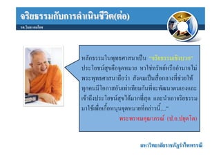
จริยธรรมกับการดําเนินชีวิต(ตอ)
รศ.วิมล เอมโอช
หลักธรรมในพุทธศาสนาเปน “จริยธรรมเชิงบวก”
ประโยชนสุขคือจุดหมาย หาใชทรัพยหรืออํานาจไม
พระพุทธศาสนาถือวา สังคมเปนสื่อกลางที่ชวยให
ทุกคนมีโอกาสอันเทาเทียมกันที่จะพัฒนาตนเองและ
เขาถึงประโยชนสุขไดมากที่สุด และนําเอาจริยธรรม
มาใชเพื่อเกื้อหนุนจุดหมายที่กลาวนี้....”
พระพรหมคุณาภรณ (ป.อ.ปยุตโต)
มหาวิทยาลัยราชภัฏรําไพพรรณี
- 5.
จริยธรรมกับการดําเนินชีวิต(ตอ)
รศ.วิมล เอมโอช
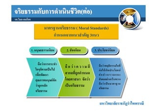
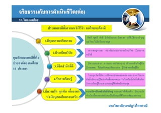
มาตรฐานจริยธรรม ( Moral Standards)
กําหนดจากแนวสําคัญ 3แนว
1. มนุษยธรรมนิยม
1. มนุษยธรรมนิยม 2. สัจจนิยม
2. สัจจนิยม 3. ประโยชนนิยม
3. ประโยชนนิยม
ถือวาการกระทํา
ถื อ ว า ค ว า ม ดี ถื อ ว า พฤติ ก รรมใดที่
ใดๆก็ตามเปนไป ก อ ให เ กิ ด ประโยชน
เพื่อพัฒนา สากลที่ถูกกําหนด ต อ ส ว น ร ว ม แ ล ะ
คุณภาพมนุษยจัด โดยศาสนา จัดวา สังคมอยางกวางขวาง
ถื อ ว า เป น มาตรฐาน
วาถูกหลัก เปนจริยธรรม จริยธรรม
จริยธรรม
มหาวิทยาลัยราชภัฏรําไพพรรณี
- 6.
จริยธรรมกับการดําเนินชีวิต(ตอ)
รศ.วิมล เอมโอช
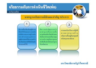
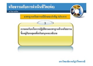
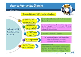
มาตรฐานจริยธรรมมีลักษณะสําคัญ 3ประการ
1 2 3
มีความเกี่ยวของกับพฤติกรรม มี ค ว า ม สํ า คั ญ ม า ก ก ว า การยอมรับหรือการปฏิบัติ
ที่ ก อ ใ ห เ กิ ด ผ ล ก ร ะ ท บ ต อ ม า ต ร ฐ า น อื่ น ๆ ร ว ม ทั้ ง
ต า ม ม า ต ร ฐ า น ด า น
สวั ส ดิ ก ารและการอยู ร ว มกั น ความเห็นแกประโยชนสวนตน
ข อ ง สั ง ค ม ม นุ ษ ย แ ล ะ ดังนั้นการกําหนดหรือควบคุม จริยธรรมขึ้นอยูกับเหตุผลที่
พฤติกรรมเหลานี้สามารถสราง ความประพฤติ ข องบุ ค คล สนับสนุนและอธิบาย
ประโยชนและกอใหเกิดโทษตอ จําเปนตองคํานึงถึงมาตรฐาน
ประชาชนทั่วไป ดานจริยธรรม
มหาวิทยาลัยราชภัฏรําไพพรรณี
- 7.
จริยธรรมกับการดําเนินชีวิต(ตอ)
รศ.วิมล เอมโอช
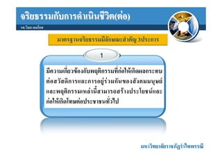
มาตรฐานจริยธรรมมีลักษณะสําคัญ 3ประการ
1
มีความเกี่ยวของกับพฤติกรรมที่กอใหเกิดผลกระทบ
ต อ สวั ส ดิ ก ารและการอยู ร ว มกั น ของสั ง คมมนุ ษ ย
และพฤติกรรมเหลานี้สามารถสรางประโยชนและ
กอใหเกิดโทษตอประชาชนทั่วไป
มหาวิทยาลัยราชภัฏรําไพพรรณี
- 8.
จริยธรรมกับการดําเนินชีวิต(ตอ)
รศ.วิมล เอมโอช
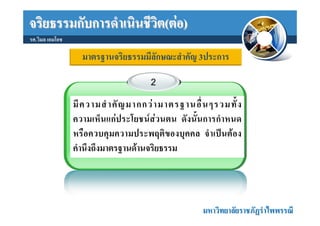
มาตรฐานจริยธรรมมีลักษณะสําคัญ 3ประการ
2
มี ค วามสํ า คั ญ มากกว า มาตรฐานอื่ น ๆรวมทั้ ง
ความเห็นแกประโยชนสวนตน ดังนั้นการกําหนด
หรือควบคุมความประพฤติของบุคคล จําเปนตอง
คํานึงถึงมาตรฐานดานจริยธรรม
มหาวิทยาลัยราชภัฏรําไพพรรณี
- 9.
- 10.
จริยธรรมกับการดําเนินชีวิต(ตอ)
รศ.วิมล เอมโอช
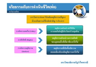
การวิเคราะหและวินิจฉัยพฤติกรรมปญหา
ดานจริยธรรมใชหลักสําคัญ 3 ประการ
พฤติกรรมดังกลาวทําใหเกิด
1.หลักความพอใจ (Utility) ความพอใจกับผูมีประโยชนรวมทุกฝาย
พฤติกรรมดังกลาวเคารพสิทธิ
2.หลักสิทธิ (Rights)
ของบุคคลอื่นที่เกี่ยวของหรือไม
3.หลักความยุติธรรม พฤติกรรมที่เกิดขึ้นมีความ
(Justices) สอดคลองกับหลักยุติธรรมหรือไม
มหาวิทยาลัยราชภัฏรําไพพรรณี
- 11.
- 12.
- 13.
จริยธรรมกับการดําเนินชีวิต(ตอ)
รศ.วิมล เอมโอช
1.กฎหมาย (Laws) หมายถึง กฎ ระเบียบ ขอบังคับที่ถกประมวลขึ้นอยางเปน
ู
ทางการในการที่จะหามหรืออนุญาตใหบุคคลกระทําการอยางใดอยางหนึ่ง
การกระทําการที่ถูกกฎหมายอาจจะสอดคลองหรือไมสอดคลองกับหลัก
จริยธรรมหรือศีลธรรม
การที่บุคคลปฏิบัตตามกฎหมายไมเปนสิ่งทีเ่ พียงพอสําหรับมาตรฐานดาน
ิ
จริยธรรมและในทํานองเดียวกัน การที่บุคคลไมปฏิบติตามกฎหมายก็ไมใช
ั
วาจะไมถูกหลักจริยธรรมเสมอไป
มหาวิทยาลัยราชภัฏรําไพพรรณี
- 14.
จริยธรรมกับการดําเนินชีวิต(ตอ)
รศ.วิมล เอมโอช
2.มารยาท หมายถึง
พฤติกรรมที่ไดรับการยอมรับในสังคม หรือความสุภาพ ออนโยนของบุคคลตอผูอน
่ื
3.จรรยาบรรณ หมายถึง
ประมวลความประพฤติที่ผูประกอบการอาชีพการงานแตละอยางกําหนดขึ้นเพื่อ
รักษาและสงเสริมเกียรติคุณชื่อเสียงและฐานะของสมาชิก อาจเขียนเปนลายลักษณ
อักษรหรือไมกได
็
โดยทั่วไปสมาชิกของวิชาชีพนันๆจะเขาใจและยอมรับรวมกันที่จะปฏิบติตาม
้ ั
จรรยาบรรณที่กาหนดขึนถาหากทําผิดจรรยาบรรณก็จะไมไดรบการยอมรับจากผูที่อยูใน
ํ ้ ั
วงการวิชาชีพเดียวกัน
มหาวิทยาลัยราชภัฏรําไพพรรณี
- 15.
- 16.
จริยธรรมกับการดําเนินชีวิต(ตอ)
รศ.วิมล เอมโอช
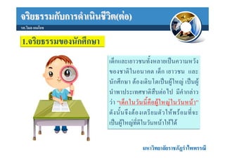
1.จริยธรรมของนักศึกษา
เด็กและเยาวชนทั้งหลายเปนความหวัง
ของชาติในอนาคต เด็ก เยาวชน และ
นักศึกษา ตองเติบโตเปนผูใหญ เปนผู
นําพาประเทศชาติสืบตอไป มีคํากลาว
ว า “เด็ ก ในวั น นี้ คื อ ผู ใ หญ ใ นวั น หน า ”
ดั ง นั้ น จึ ง ต อ งเตรี ย มตั ว ให พ ร อ มที่ จ ะ
เปนผูใหญที่ดีในวันหนาใหได
มหาวิทยาลัยราชภัฏรําไพพรรณี
- 17.
จริยธรรมกับการดําเนินชีวต(ตอ)
ิ
รศ.วิมล เอมโอช
ประเทศชาติตั้งความหวังไววา คนไทยจะตองมี
คิ ด ดี พู ด ดี ทํา ดี มี ค า นิ ย มและวั ฒ นธรรมที่ ดี รู จั ก บาป-บุ ญ
1.มีคุณธรรมจริยธรรม คุณโทษ ไมติดในอบายมุข
เคารพกฎจราจร ตรงตอเวลาแตงกายเรียบรอย รูบทบาท
2.มีระเบียบวินัย หนาที่
คุณลักษณะคนดีที่พึง
ประสงคของคนไทย มีความละอาย ความเกรงกลัวต อบาป เห็ นอกเห็นใจผูอื่น
3.มีจิตสํานึกที่ดี รูกาลเทศะ ไมคุยกันขณะฟงบรรยาย รูจักชวยเหลือผูอื่น
10 ประการ
โลกทุ ก วั น นี้ มีก ารเปลี่ ย นแปลงตลอดเวลาและรวดเร็ว มาก
4.รักการเรียนรู ดังนั้นมีความรูใหมๆเกิดขึ้นตลอดเวลาในโลกใบนี้ดังนั้นจึงตอง
รักการเรียนรูจึงจะสามารถอยูไดอยางมีความสุข
5.มีความรัก ผูกพัน เอื้ออาทร ความรัก=เปนพลังอันยิ่งใหญ ครอบครัวที่เข็มแข็ง มีความรัก
หวงใยบุคคลในครอบครัว หวงใย เอื้ออาทรตอกันจะเปนตนทุนที่ดีในการพัฒนาเยาวชน
มหาวิทยาลัยราชภัฏรําไพพรรณี
- 18.
จริยธรรมกับการดําเนินชีวต(ตอ)
ิ
รศ.วิมล เอมโอช
ประเทศชาติตั้งความหวังไววา คนไทยจะตองมี(ตอ)
วัฒนธรรมประเพณีไทยเปนมรดกที่ล้ําคาเปนสิ่งที่แสดงความ
6.รักความเปนไทย เปนไทย ชาติไทย
และวัฒนธรรมไทย
7.มีสุขภาพกาย พลังความคิดสติปญญายอมอยูในรางกายที่เข็งแรง สุขภาพจิต
เปนสิ่งสําคัญที่ทําใหรางกายแข็งแรง เกิดสติปญญาตองปฏิบัติ
คุณลักษณะคนดีที่พึง และสุขภาพจิตดี ในชีวิตจริงที่มิใชอยูในแตหนังสือ
ประสงคของคนไทย 8.มีวิถีชีวตแบบ
ิ
- คารวะธรรม - สามัคคีธรรม - ปญญาธรรม
10 ประการ ประชาธิปไตย
สิ่งชั่วรายหกประการจะทําใหชีวิต ควรหลีกหนีใหพน
9.ไมมั่วสุมอบายมุข เกียจคราน- เที่ยวกลางคืน - ดูการละเลน
เลนการพนัน - คบคนชัว- ดื่มของมึนเมา
่
10.ดําเนินชีวตแบบ
ิ ความพอเพียงหมายถึง
-ความพอประมาณ - ความมีเหตุผล – มีระบบภูมิคมกัน ุ
เศรษฐกิจพอเพียง มีคุณธรรม (ซื่อสัตย สุจริต แบงปน ใชความรอบรู)
ดําเนินชีวิต (ดวยความเพียร อดทน มีสติปญญา สามัคคี)
มหาวิทยาลัยราชภัฏรําไพพรรณี
- 19.
จริยธรรมกับการดําเนินชีวต(ตอ)
ิ
รศ.วิมล เอมโอช
จะปลูกพืชตองเตรียมดิน
จะกินตองเตรียมอาหาร
จะพัฒนาการตองเตรียมคน
จะพัฒนาคนตองเริมที่ใจ
่
จะพัฒนาใครเขา ก็ตองเริ่มที่เรากอน
มหาวิทยาลัยราชภัฏรําไพพรรณี
- 20.
จริยธรรมกับการดําเนินชีวต(ตอ)
ิ
รศ.วิมล เอมโอช
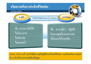
1.สติ 1.หลักธรรมมีอุปการะมาก มี 2 ประการ 2.สัมปชัญญะ
คือ ความระลึกได คือ ความรูตัว ปฏิบัติ
ไมประมาท ในทางถูกตองเหมาะสม
ไมเลินเลอ เตือนตนใหรอดพน
ไมเผลอตัว
ธรรมะ 2 ประการนี้ จะทําใหผประพฤติปฏิบัติรอดพนภัยไดเสมอ คนมักพบกับความทุกข
ู
ตาง ๆ อันเนื่องจากขาดสติสัมปชัญญะ
- 21.
จริยธรรมกับการดําเนินชีวต(ตอ)
ิ
รศ.วิมล เอมโอช
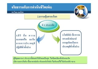
2.ธรรมคุมครองโลก
มี 2 ประการคือ
1.หิ ริ คื อ ค ว า ม 2.โอตัปปะ คือ ความ
ละอายแกใจ ละเวน เกรงกลัวตอบาป
จ า ก ก า ร ป ร ะ พ ฤ ติ การทุจริตหรือการ
ปฏิบัติชั่วทั้งปวง ประพฤติชั่วทั้งปวง
ผูมีคุณธรรม 2 ประการนี้ยอมทําใหสังคมเปนสุข ไมเบียดเบียนซึงกันและกัน
่
(มีความเกรงใจกัน เอื้ออาทรตอกัน เห็นอกเห็นใจกัน ไมเห็นแกได ไมเห็นแกตัวฯลฯ)
- 22.
จริยธรรมกับการดําเนินชีวต(ตอ)
ิ
รศ.วิมล เอมโอช
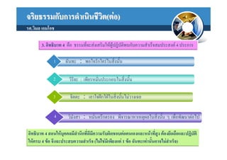
3. อิทธิบาท 4 คือ ธรรมที่จะสงเสริมใหผูปฏิบัติพบกับความสําเร็จสมประสงค 4 ประการ
1 ฉันทะ : พอใจรักใครในสิงนั้น
่
2 วิริยะ : เพียรหมั่นประกอบในสิงนัน
่ ้
3 จิตตะ : เอาใจฝกใฝในสิ่งนั้นไมวางเฉย
4 วิมังสา : หมั่นตรึกตรอง พิจารณาหาเหตุผลในสิงนั้น ๆ เพื่อพัฒนาตอไป
่
อิทธิบาท 4 สอนใหบุคคลมีสํานึกที่ดีมีความรับผิดชอบตอตนเองและหนาที่สูง ตองยึดถือและปฏิบติ
ั
ใหครบ 4 ขอ จึงจะประสบความสําเร็จ (ไมใชมีเพียงแค 1 ขอ ฉันทะเทานันอาจไมสําเร็จ)
้
- 23.
จริยธรรมกับการดําเนินชีวต(ตอ)
ิ
รศ.วิมล เอมโอช
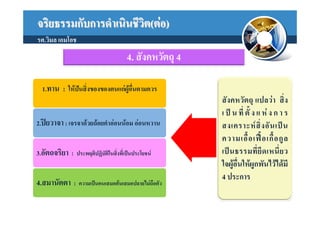
4. สังคหวัตถุ 4
1.ทาน : ใหปนสิ่งของของตนแกผูอื่นตามควร
สังคหวัตถุ แปลวา สิ่ง
เ ป น ที่ ตั้ ง แ ห ง ก า ร
2.ปยวาจา : เจรจาดวยถอยคําออนนอม ออนหวาน สงเคราะห สิ่ ง อั น เป น
ความเอื้ อ เฟ อ เกื้ อ กู ล
3.อัตถจริยา : ประพฤติปฏิบัติในสิ่งที่เปนประโยชน เป น ธรรมที่ ยึ ด เหนี่ ย ว
ใจผูอื่นใหผูกพันไวไดมี
4 ประการ
4.สมานัตตา : ความเปนคนเสมอตนเสมอปลายไมถือตัว
- 24.
จริยธรรมกับการดําเนินชีวต(ตอ)
ิ
รศ.วิมล เอมโอช
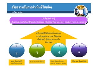
5.หัวใจนักปราชญ
5.หัวใจนักปราชญ
เปนธรรมที่สงงเสริมใหผูปฏิบัตเิ เิ ปนนักปราชญ เปนผูรอบรูใในศาสตรตาางๆ ตามที่ปรารถนา มี 4 ประการ
เปนธรรมที่ส เสริมใหผูปฏิบัต ปนนักปราชญ เปนผูรอบรู นศาสตรต งๆ ตามที่ปรารถนา มี 4 ประการ
ผูประพฤติปฏิบัติอยางสม่ําเสมอและ
ครบถวนทุกประการจะนําไปสูความ
เปนผูรอบรู ผูเชี่ยวชาญ และเปน
นักปราชญ
1 2 3 4
สุ จิ ปุ ลิ
สุตตะ ฟงอยางตั้งใจ จินตะ คิดตามในสิ่งที่ฟง
ปุจฉา ซักถาม พิจารณา ลิขิต /จด/ เขียน บันทึก
รวมทั้งการอานดวย ทบทวน ไตรตรอง ทดลอง
- 25.
จริยธรรมกับการดําเนินชีวต(ตอ)
ิ
รศ.วิมล เอมโอช
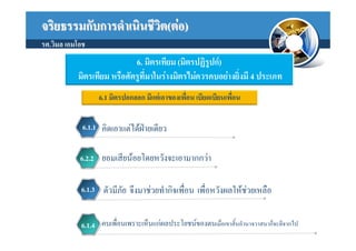
6. มิตรเทียม (มิตรปฏิรูปก)
มิตรเทียม หรือศัตรูที่มาในรางมิตรไมควรคบอยางยิ่งมี 4 ประเภท
6.1 มิตรปอกลอก มีแตเอาของเพื่อน เบียดเบียนเพื่อน
6.1.1 คิดเอาแตไดฝายเดียว
6.2.2 ยอมเสียนอยโดยหวังจะเอามากกวา
6.1.3 ตัวมีภัย จึงมาชวยทํากิจเพื่อน เพื่อหวังผลใหชวยเหลือ
6.1.4 คบเพื่อนเพราะเห็นแกผลประโยชนของตนเมื่อเขาสิ้นอํานาจวาสนาก็จะตีจากไป
- 26.
จริยธรรมกับการดําเนินชีวต(ตอ)
ิ
รศ.วิมล เอมโอช
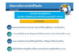
6. มิตรเทียม (มิตรปฏิรูปก) ตอ
มิตรเทียม หรือศัตรูที่มาในรางมิตรไมควรคบอยางยิ่งมี 4 ประเภท
6.2 มิตรดีแตพูด
6.2.1 เก็บเอาของลวงแลวมาปราศรัย (เชน “คิดจะแบงใหแตรออยูไมเห็นมา ขณะนี้หมดแลว”)
6.2.2 อางเอาของที่ยังไมมีมาปราศรัย เพื่อปลุกปลอบใจ เพื่อใหชวยทําธุระให (เชน “ถาทํางานนี้เสร็จจะใหเพื่อ 50 %เลย)
6.2.3 สงเคราะหดวยสิ่งทําประโยชนมิได (พูดในสิ่งไรสาระ ไมมีคุณคา ไมมประโยชนอันใด)
ี
6.2.4 เมื่อเพื่อนมีกิจอางแตเหตุขัดของ (เพือขอความชวยเหลือจะอางเหตุขัดของไปตาง ๆ นานา)
่
- 27.
จริยธรรมกับการดําเนินชีวต(ตอ)
ิ
รศ.วิมล เอมโอช
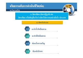
6. มิตรเทียม (มิตรปฏิรูปก) ตอ
มิตรเทียม หรือศัตรูที่มาในรางมิตรไมควรคบอยางยิ่งมี 4 ประเภท
6.3 มิตรหัวประจบ
6.3.1 จะทําชัวก็คลอยตาม
่
6.3.2 จะทําดีก็คลอยตาม
6.3.3 ตอหนาสรรเสริญ
6.3.4 ลับหลังนินทา
- 28.
จริยธรรมกับการดําเนินชีวต(ตอ)
ิ
รศ.วิมล เอมโอช
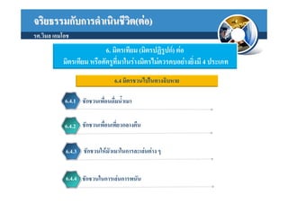
6. มิตรเทียม (มิตรปฏิรูปก) ตอ
มิตรเทียม หรือศัตรูที่มาในรางมิตรไมควรคบอยางยิ่งมี 4 ประเภท
6.4 มิตรชวนไปในทางฉิบหาย
6.4.1 ชักชวนเพื่อนดื่มน้ําเมา
6.4.2 ชักชวนเพื่อนเที่ยวกลางคืน
6.4.3 ชักชวนใหมัวเมาในการละเลนตาง ๆ
6.4.4 ชักชวนในการเลนการพนัน
- 29.
จริยธรรมกับการดําเนินชีวต(ตอ)
ิ
รศ.วิมล เอมโอช
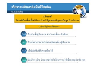
7. มิตรแท
มิตรแทเปนเพื่อนที่แทจริง จะนําพาไปสูความเจริญและเปนสุข มี 4 ประเภท
7.1 มิตรมีอุปการะมีลักษณะ4
7.2.1 ปองกันเพื่อผูประมาท ชวยรักษาเพื่อน ตักเตือน
7.2.2 ปองกันชวยรักษาทรัพยสมบัติของเพื่อนผูประมาท
7.2.3 เมื่อมีภัยเปนที่พึ่งของเพื่อนได
7.2.4 เมื่อมีกิจจําเปน ชวยออกทรัพยใหเกินกวาจะใหเพื่อนออกปากรองขอ
- 30.
จริยธรรมกับการดําเนินชีวต(ตอ)
ิ
รศ.วิมล เอมโอช
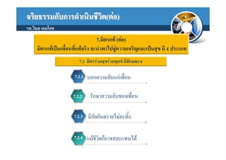
7.มิตรแท (ตอ)
มิตรแทเปนเพื่อนที่แทจริง จะนําพาไปสูความเจริญและเปนสุข มี 4 ประเภท
7.2 มิตรรวมสุขรวมทุกข มีลักษณะ4
7.2.1 บอกความลับแกเพื่อน
7.2.2 รักษาความลับของเพื่อน
7.2.3 มีภัยอันตรายไมละทิ้ง
7.2.4 แมชวิตก็อาจสละแทนได
ี
- 31.
จริยธรรมกับการดําเนินชีวต(ตอ)
ิ
รศ.วิมล เอมโอช
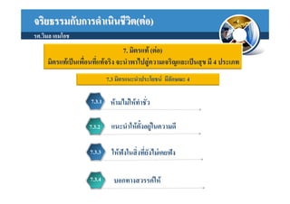
7. มิตรแท (ตอ)
มิตรแทเปนเพื่อนที่แทจริง จะนําพาไปสูความเจริญและเปนสุข มี 4 ประเภท
7.3 มิตรแนะนําประโยชน มีลักษณะ 4
7.3.1 หามไมใหทําชั่ว
7.3.2 แนะนําใหตั้งอยูในความดี
7.3.3 ใหฟงในสิ่งที่ยังไมเคยฟง
7.3.4 บอกทางสวรรคให
- 32.
จริยธรรมกับการดําเนินชีวต(ตอ)
ิ
รศ.วิมล เอมโอช
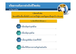
7.มิตรแท (ตอ)
มิตรแทเปนเพื่อนที่แทจริง จะนําพาไปสูความเจริญและเปนสุข มี 4 ประเภท
7.4 มิตรมีใจรัก มีลักษณะ 4
7.4.1 เพื่อนมีทกข ทุกขดวย
ุ
7.4.2 เพื่อนมีสุข สุขดวย
7.4.3 เพื่อนถูกติเตียน ชวยแกไขให
7.4.4 เพื่อนไดรับการสรรเสริญชวยสงเสริม
- 33.
จริยธรรมกับการดําเนินชีวต(ตอ)
ิ
รศ.วิมล เอมโอช
ตั้งใจ
ถาหมั่นเพียร เรียนอะไร ก็ตองรู
ถาหมั่นดู ดูอะไร ก็ตองเห็น
ถาหมั่นทํา ทําอะไร ก็ตองเปน
ถาไมเลน หมั่นแตทํา จักจําเริญ
ถาครานเรียน เรียนอะไร ก็ไมรู
ถาครานดู ดูอะไร ก็ไมเห็น
ถาครานทํา ทําอะไร ก็ไมเปน
ตองลําเค็ญ เปนขอทาน เพราะครานเอย
จาก วัดสวนแกว
ขอคิดเตือนใจสําหรับนักเรียนนักศึกษา เพือนําไปสูความสําเร็จในชีวิต
่