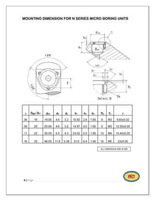
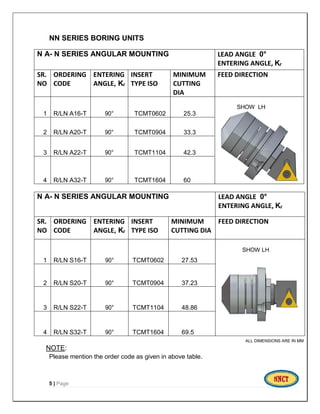
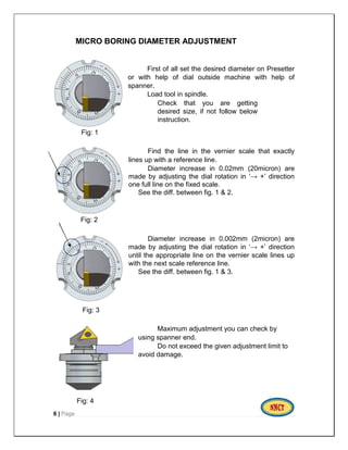
CATALOGUE 2016
Micro Boring Unit
Specialist in Boring Bar for VMC and HMC special Tooling
N. N. CUTTING TOOLS
 PLOT NO. 318, SECTOR 10, SOHAM
INDUSTRIAL COMPLEX, 1ST FLOOR, SHOP
NO. 4, BHOSARI MIDC, PUNE – 411026
 CEO- MAGAR N. N.
MOBILE- 09860081448
 MAIL ID- nncuttingtoold@gmail.com
WEBSITE – www.nncuttingtools.com
NN SERIES - MICRO BORING UNIT
NN Series fine boring units are specifically designed for building into boring
bars which are high precision machining for specific bore size.
IMPORTANT POINT:
 Can be mounted in blind holes.
 Adjustment is made from the front side.
 The units are self-locking i.e. there is no need for unlocking before or
locking after setting.
PLEASE NOTE:
 When setting a unit, mounting in angular position, the axial position
changes equal to radial movement/tan 53° 8’.
 When designing special tools, please calculate the nominal diameter to
be machined with the unit set to the centre of the adjustment range, ‘X’
this makes it possible to adjust the nominal bore plus and minus.
 Never unscrew the cartridge further than indicated by the letter ‘X’
Maximum of the setting key for the unit concerned. If the limit is
exceeded the unit cannot be repaired.
 Two types of Mounting are available in Micro Boring Unit, they are
Angular Mounting & Straight Mounting.
1 | Page
1. ANGULAR MOUNTING
ANGULAR MOUNTING - LEFT HAND SHOW (L N A)
SR. UNIT SIZE X DIAMETER D c F1 Dm L1 L2
NO. D h7
1 R/L N A16-T 1.7 25.3 Min. 24 0.45 16 25.6 14.5
2 R/L N A20-T 2.1 33.3 Min. 31.5 0.9 20 33.7 18.8
3 R/L N A22-T 2.8 42.3 Min. 39.5 1.1 22 45.3 23.2
4 R/L N A32-T 5.0 60 Min. 56.5 1.2 32 63.7 32.6
ALL DIMENSIONS ARE IN MM
NOTE:
Where Kᵣ = Entering angle.
X is denoting to understand Minimum and Maximum travel of Cartridge
form zero conduction.
2 | Page
2. STRAIGHT MOUNTING
STRAIGHT MOUNTING AND LEFT HAND SHOW (L N S)
SR. UNIT SIZE X DIAMETER D c F1 Dm L1 L2
NO. D
1 R/L N S16 1.7 27.5 Min. 26.0 5.1 16 24.1 13
2 R/L N S20 2.1 37.2 Min. 34.9 6.2 20 32.5 17.8
3 R/L N S22 2.8 48.8 Min. 46.9 7.2 22 45.8 23.8
4 R/L N S32 5.0 69.5 Min. 67 10.3 32 62.8 31.7
ALL DIMENSIONS ARE IN MM
NOTE:
Where Kᵣ = Entering angle
X is denoting to understand Minimum and Maximum travel of Cartridge
form zero conduction.
3 | Page
MOUNTING DIMENSION FOR N SERIES MICRO BORING UNITS
∆ Dm / DH7 dH9 d2 d3 h1 h2 h3 TL Th r
06 16 19.05 4.6 3.2 10.93 2.8 1.65 9 M3 9.65±0.02
09 20 25.05 4.6 3.2 14.97 4.0 1.65 9 M3 12.50±0.05
11 22 30.05 6.5 4.3 23.02 5.0 1.85 13 M4 15.40±0.05
16 32 46.05 11.8 5.38 31.9 6.4 1.95 16 M5 23±0.05
4 | Page
ALL DIMENSION ARE IN MM
NN SERIES BORING UNITS
N A- N SERIES ANGULAR MOUNTING LEAD ANGLE 0°
ENTERING ANGLE, Kᵣ
SR.
NO
ORDERING
CODE
ENTERING
ANGLE, Kᵣ
INSERT
TYPE ISO
MINIMUM
CUTTING
DIA
FEED DIRECTION
1 R/LN A16-T 90° TCMT0602 25.3
SHOW LH
2 R/LN A20-T 90° TCMT0904 33.3
3 R/LN A22-T 90° TCMT1104 42.3
4 R/LN A32-T 90° TCMT1604 60
N A- N SERIES ANGULAR MOUNTING LEAD ANGLE 0°
ENTERING ANGLE, Kᵣ
SR.
NO
ORDERING
CODE
ENTERING
ANGLE, Kᵣ
INSERT
TYPE ISO
MINIMUM
CUTTING DIA
FEED DIRECTION
1 R/LN S16-T 90° TCMT0602 27.53
SHOW LH
2 R/LN S20-T 90° TCMT0904 37.23
3 R/LN S22-T 90° TCMT1104 48.86
4 R/LN S32-T 90° TCMT1604 69.5
ALL DIMENSIONS ARE IN MM
NOTE:
Please mention the order code as given in above table.
5 | Page
MICRO BORING DIAMETER ADJUSTMENT
First of all set the desired diameter on Presetter
or with help of dial outside machine with help of
spanner.
Load tool in spindle.
Check that you are getting
desired size, if not follow below
instruction.
Fig: 1
Find the line in the vernier scale that exactly
lines up with a reference line.
Diameter increase in 0.02mm (20micron) are
made by adjusting the dial rotation in ‘→ +’ direction
one full line on the fixed scale.
See the diff. between fig. 1 & 2.
Fig: 2
Diameter increase in 0.002mm (2micron) are
made by adjusting the dial rotation in ‘→ +’ direction
until the appropriate line on the vernier scale lines up
with the next scale reference line.
See the diff. between fig. 1 & 3.
Fig: 3
Maximum adjustment you can check by
using spanner end.
Do not exceed the given adjustment limit to
avoid damage.
Fig: 4
6 | Page
1. nnct catalogue 2016

1. nnct catalogue 2016

  • 1.
    CATALOGUE 2016 Micro BoringUnit Specialist in Boring Bar for VMC and HMC special Tooling N. N. CUTTING TOOLS  PLOT NO. 318, SECTOR 10, SOHAM INDUSTRIAL COMPLEX, 1ST FLOOR, SHOP NO. 4, BHOSARI MIDC, PUNE – 411026  CEO- MAGAR N. N. MOBILE- 09860081448  MAIL ID- nncuttingtoold@gmail.com WEBSITE – www.nncuttingtools.com
  • 2.
    NN SERIES -MICRO BORING UNIT NN Series fine boring units are specifically designed for building into boring bars which are high precision machining for specific bore size. IMPORTANT POINT:  Can be mounted in blind holes.  Adjustment is made from the front side.  The units are self-locking i.e. there is no need for unlocking before or locking after setting. PLEASE NOTE:  When setting a unit, mounting in angular position, the axial position changes equal to radial movement/tan 53° 8’.  When designing special tools, please calculate the nominal diameter to be machined with the unit set to the centre of the adjustment range, ‘X’ this makes it possible to adjust the nominal bore plus and minus.  Never unscrew the cartridge further than indicated by the letter ‘X’ Maximum of the setting key for the unit concerned. If the limit is exceeded the unit cannot be repaired.  Two types of Mounting are available in Micro Boring Unit, they are Angular Mounting & Straight Mounting. 1 | Page
  • 3.
    1. ANGULAR MOUNTING ANGULARMOUNTING - LEFT HAND SHOW (L N A) SR. UNIT SIZE X DIAMETER D c F1 Dm L1 L2 NO. D h7 1 R/L N A16-T 1.7 25.3 Min. 24 0.45 16 25.6 14.5 2 R/L N A20-T 2.1 33.3 Min. 31.5 0.9 20 33.7 18.8 3 R/L N A22-T 2.8 42.3 Min. 39.5 1.1 22 45.3 23.2 4 R/L N A32-T 5.0 60 Min. 56.5 1.2 32 63.7 32.6 ALL DIMENSIONS ARE IN MM NOTE: Where Kᵣ = Entering angle. X is denoting to understand Minimum and Maximum travel of Cartridge form zero conduction. 2 | Page
  • 4.
    2. STRAIGHT MOUNTING STRAIGHTMOUNTING AND LEFT HAND SHOW (L N S) SR. UNIT SIZE X DIAMETER D c F1 Dm L1 L2 NO. D 1 R/L N S16 1.7 27.5 Min. 26.0 5.1 16 24.1 13 2 R/L N S20 2.1 37.2 Min. 34.9 6.2 20 32.5 17.8 3 R/L N S22 2.8 48.8 Min. 46.9 7.2 22 45.8 23.8 4 R/L N S32 5.0 69.5 Min. 67 10.3 32 62.8 31.7 ALL DIMENSIONS ARE IN MM NOTE: Where Kᵣ = Entering angle X is denoting to understand Minimum and Maximum travel of Cartridge form zero conduction. 3 | Page
  • 5.
    MOUNTING DIMENSION FORN SERIES MICRO BORING UNITS ∆ Dm / DH7 dH9 d2 d3 h1 h2 h3 TL Th r 06 16 19.05 4.6 3.2 10.93 2.8 1.65 9 M3 9.65±0.02 09 20 25.05 4.6 3.2 14.97 4.0 1.65 9 M3 12.50±0.05 11 22 30.05 6.5 4.3 23.02 5.0 1.85 13 M4 15.40±0.05 16 32 46.05 11.8 5.38 31.9 6.4 1.95 16 M5 23±0.05 4 | Page ALL DIMENSION ARE IN MM
  • 6.
    NN SERIES BORINGUNITS N A- N SERIES ANGULAR MOUNTING LEAD ANGLE 0° ENTERING ANGLE, Kᵣ SR. NO ORDERING CODE ENTERING ANGLE, Kᵣ INSERT TYPE ISO MINIMUM CUTTING DIA FEED DIRECTION 1 R/LN A16-T 90° TCMT0602 25.3 SHOW LH 2 R/LN A20-T 90° TCMT0904 33.3 3 R/LN A22-T 90° TCMT1104 42.3 4 R/LN A32-T 90° TCMT1604 60 N A- N SERIES ANGULAR MOUNTING LEAD ANGLE 0° ENTERING ANGLE, Kᵣ SR. NO ORDERING CODE ENTERING ANGLE, Kᵣ INSERT TYPE ISO MINIMUM CUTTING DIA FEED DIRECTION 1 R/LN S16-T 90° TCMT0602 27.53 SHOW LH 2 R/LN S20-T 90° TCMT0904 37.23 3 R/LN S22-T 90° TCMT1104 48.86 4 R/LN S32-T 90° TCMT1604 69.5 ALL DIMENSIONS ARE IN MM NOTE: Please mention the order code as given in above table. 5 | Page
  • 7.
    MICRO BORING DIAMETERADJUSTMENT First of all set the desired diameter on Presetter or with help of dial outside machine with help of spanner. Load tool in spindle. Check that you are getting desired size, if not follow below instruction. Fig: 1 Find the line in the vernier scale that exactly lines up with a reference line. Diameter increase in 0.02mm (20micron) are made by adjusting the dial rotation in ‘→ +’ direction one full line on the fixed scale. See the diff. between fig. 1 & 2. Fig: 2 Diameter increase in 0.002mm (2micron) are made by adjusting the dial rotation in ‘→ +’ direction until the appropriate line on the vernier scale lines up with the next scale reference line. See the diff. between fig. 1 & 3. Fig: 3 Maximum adjustment you can check by using spanner end. Do not exceed the given adjustment limit to avoid damage. Fig: 4 6 | Page