Download as PDF, PPTX


![www.ambit.de
Chapter 3
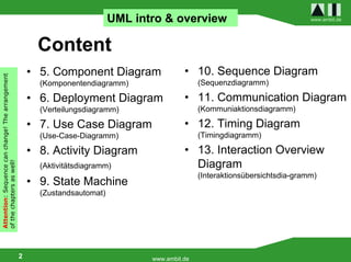
Fourth Diagram Type
Behaviour Modelling
[Verhaltensmodellierung]
16 www.ambit.de [Rupp et.a] S. 225-236](https://image.slidesharecdn.com/05aiumlillikstudentspart2eng-110107134418-phpapp01/85/05-ai-uml_illik_students_part_2_eng-16-320.jpg)
![www.ambit.de
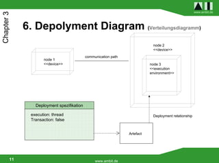
Chapter 3
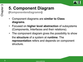
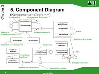
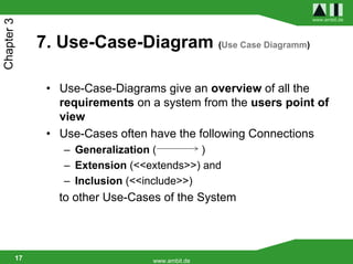
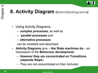
8. Activity Diagram (Aktivitätsdiagramm)
Activity name activity
Start node get invitation possible order
Invitation Check date
object node
Check interest
[time available] in invitation
action
[no time]
link [no interest]
[interest]
condition Announce
Cancel invitation
participation
control node /
decision node
end node
24 www.ambit.de](https://image.slidesharecdn.com/05aiumlillikstudentspart2eng-110107134418-phpapp01/85/05-ai-uml_illik_students_part_2_eng-24-320.jpg)
![www.ambit.de
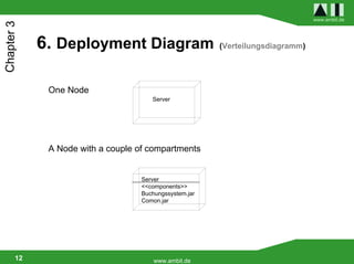
Chapter 3
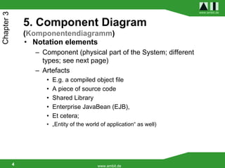
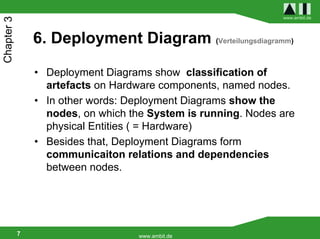
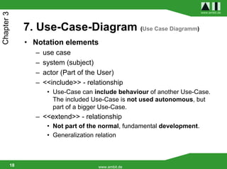
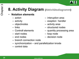
8. Activity Diagram (Aktivitätsdiagramm)
Wrapping a gift
[Recipient lives far away]
Adress the Label
Christmas
present Wrap the gift
Put it under a tree
[Recipient lives near by]
A branch node / Decision in the Activity Diagram
25 www.ambit.de](https://image.slidesharecdn.com/05aiumlillikstudentspart2eng-110107134418-phpapp01/85/05-ai-uml_illik_students_part_2_eng-25-320.jpg)
![www.ambit.de
Chapter 3
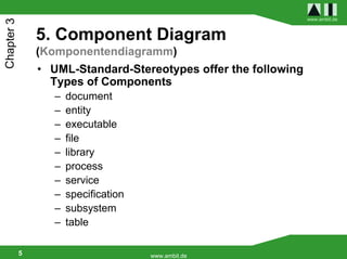
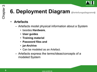
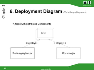
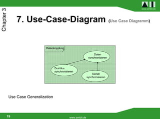
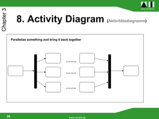
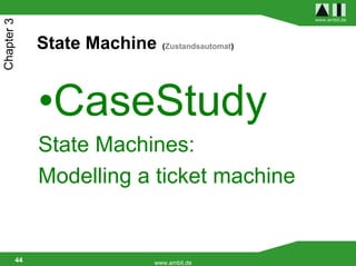
9. State Machine (Zustandsautomat)
State machine name
Trigger Guard
ticket machine
Start state
Action Labels:
value heighten [value<price]
waiting Geldaufnahme entry
[enter coins]
Do exit
state [enter coins]/ do
value heighten include
Cancel voted ticket
stopp selectively
pressed
Transition cancel
Berechnung
Entry / value
expend After do / price
(Timeout) calculate
Crossing point
[value = price] [value>price]
Output ricket
entrance behaviour Entry / ticket
output
expend
change
do / change
expend State behavior
TimeTrigger
29 www.ambit.de](https://image.slidesharecdn.com/05aiumlillikstudentspart2eng-110107134418-phpapp01/85/05-ai-uml_illik_students_part_2_eng-29-320.jpg)
![www.ambit.de
Chapter 3
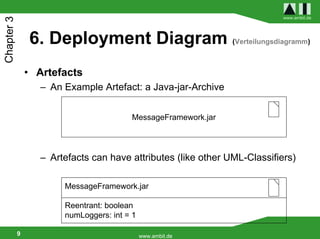
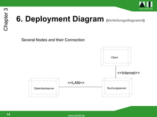
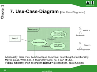
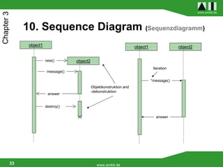
10. Sequence Diagram (Sequenzdiagramm)
object1 object2 object1 object2
message()
(a-b<2 sec.) a
[x>0] message1()
b
answer Aktionssequenz /
Zusicherung / Action sequence
assertion [x<=0] message2()
Rekursion /
recursion answer1
Steuerungs- answer2
Fokus /
Control focus
life line
32 www.ambit.de](https://image.slidesharecdn.com/05aiumlillikstudentspart2eng-110107134418-phpapp01/85/05-ai-uml_illik_students_part_2_eng-32-320.jpg)
![www.ambit.de
Chapter 3
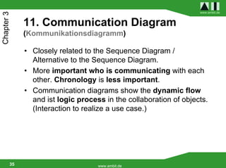
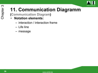
11. Communication Diagram
(Kommunikationsdiagramm)
sequential
Object:class synchronize
[Condition] 1.2:answer:=message(arg.)
restricted
Start
Object:class Object:class
1.1.*.message(arguments) Time-dependend
message()
asyncron
Sequence
Messages are displayed with lines between communication partners.
37 www.ambit.de](https://image.slidesharecdn.com/05aiumlillikstudentspart2eng-110107134418-phpapp01/85/05-ai-uml_illik_students_part_2_eng-37-320.jpg)
![www.ambit.de
Chapter 3
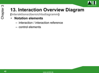
13. Interaction Overview Diagram
(Interaktionsübersichtsdiagramm)
Geldautomat
ref
ref {0..10} Zeiteinheit
PIN Eingabe Minuten
Karteneinschub
[Dauer > 10] Interaktionsreferenz
Startknoten
[else]
Paralellisierungsknoten ref
[PIN Eingabe [PIN Eingabe
== fehlgeschlagen] == 0] Geldtransaktion
abwickeln
sd
ref
:Authentifizierungs- Verzweigungsknoten
:Display
system Karteneinzug ref
Anzeigen („Karte
wird eingezogen“) Kartenauswurf
Verbindungsknoten
Kante Synchronisationsknoten Endknoten
43 www.ambit.de](https://image.slidesharecdn.com/05aiumlillikstudentspart2eng-110107134418-phpapp01/85/05-ai-uml_illik_students_part_2_eng-43-320.jpg)
The document discusses knowledge and how it enables business ambitions. It states that the company delivers knowledge and creates value for customers worldwide. It then provides an introduction to UML diagrams, listing 13 different types of diagrams that will be covered.