1. IPI’s Methodology for Implementing Sustainable Energy-Saving Strategies in Collections Environments (2017)
9
HVAC BASICS
INTRODUCTION:
Air Handling System
Components/Layout:
Dampers
Filters
Cooling Coil
Heating Coil
Humidifier
Supply Fan
Diffusers
Return Fan
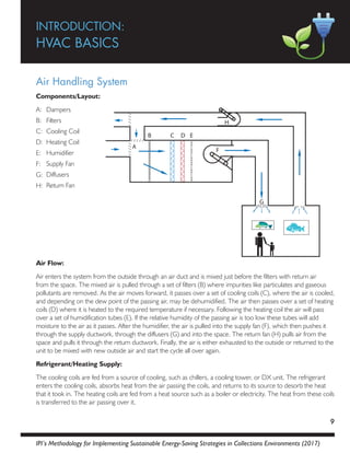
Air Flow:
Air enters the system from the outside through an air duct and is mixed just before the filters with return air
from the space. The mixed air is pulled through a set of filters (B) where impurities like particulates and gaseous
pollutants are removed. As the air moves forward, it passes over a set of cooling coils (C), where the air is cooled,
and depending on the dew point of the passing air, may be dehumidified. The air then passes over a set of heating
coils (D) where it is heated to the required temperature if necessary. Following the heating coil the air will pass
over a set of humidification tubes (E). If the relative humidity of the passing air is too low these tubes will add
moisture to the air as it passes. After the humidifier, the air is pulled into the supply fan (F), which then pushes it
through the supply ductwork, through the diffusers (G) and into the space. The return fan (H) pulls air from the
space and pulls it through the return ductwork. Finally, the air is either exhausted to the outside or returned to the
unit to be mixed with new outside air and start the cycle all over again.
Refrigerant/Heating Supply:
The cooling coils are fed from a source of cooling, such as chillers, a cooling tower, or DX unit. The refrigerant
enters the cooling coils, absorbs heat from the air passing the coils, and returns to its source to desorb the heat
that it took in. The heating coils are fed from a heat source such as a boiler or electricity. The heat from these coils
is transferred to the air passing over it.
A
B C D E
F
H
G
A:
B:
C:
D:
E:
F:
G:
H:
2. 10
IPI’s Methodology for Implementing Sustainable Energy-Saving Strategies in Collections Environments (2017)
System Variations:
1. A system may have multiple sets of filters to remove different levels of impurities.
2. The arrangement of the cooling coil and heating coil may vary from unit to unit.
3. A cooling coil may not be present in every unit or may be before the outside air dampers for pre-
cooling.
4. A heating coil may not be present in every unit.
5. The main heating coil may be farther down the line in the ductwork in what is called a reheat. As a reheat
the coil will heat air for a specific space just before it is discharged from the ducts.
6. A system may utilize a bypass setup where the air can be diverted past the coil(s) if it does not need to be
treated.
7. Humidification tubes may not be present in every unit or may be farther down in the ductwork just before
the diffusers.
8. A return fan may not be present on every unit if the supply fan creates enough of a draw to pull the air
back through the space.
Heating/Cooling System
Components/Layout:
Dampers
Filters
Heating Coil
Cooling Coil
Humidifier
Supply Fan
Return Fan
Air Flow:
This type of unit is most common in environments where moisture removal from the air is not much of a
concern. Starting at the outside air intake, air enters the outside air duct and is mixed with return air from the
space just before the filters (B). This mixed air is pulled through a set of filters where impurities are removed. The
air then passes over a set of heating coils (C) where it is heated to the required temperature if necessary. Next the
air passes over a set of cooling coils (D); here it is sensibly cooled to the desired temperature if necessary. After
the cooling coil the air passes over a set of humidification tubes. If the relative humidity of the air is too low these
tubes will add moisture to the air as it passes. After the humidifiers, the air is pulled into the supply fan (F), which
pushes it through the supply ductwork, through the diffusers and into the space. The return fan (G) will pull in air
from the space and push it through the return ductwork. The air is either exhausted or returned to the unit to be
mixed with outside air and start the cycle all over again.
Refrigerant/Heating Supply:
The cooling coils are fed from a source of cooling, such as chillers, a cooling tower, or DX unit. The refrigerant
enters the cooling coils, absorbs heat from the air passing the coils, and returns to the source to desorb the heat
A
B C D E
G
F
F
A:
B:
C:
D:
E:
F:
G:
3. IPI’s Methodology for Implementing Sustainable Energy-Saving Strategies in Collections Environments (2017)
11
that it took in.
The heating coils are fed from a heat source such as a boiler or electricity. The heat from these coils is transferred
to the air passing over it.
System Variations:
1. A system may have multiple sets of filters to remove different levels of impurities.
2. A cooling coil may be before the outside air dampers for pre-cooling.
3. The system may utilize a bypass setup where the air can be diverted past the coil(s) if it does not need to
be treated.
4. Humidification tubes may not be present in every unit or may be farther down in the ductwork just before
the diffusers.
5. A return fan may not be present on every unit if the supply fan creates enough of a draw to pull the air
back through the system.
Preheat System
Components/Layout:
Dampers
Filters
Cooling Coil
Heating Coil
Humidifier
Supply Fan
Return Fan
Preheat Coils
Air Flow:
This system is a standard air handling unit that utilizes a preheat coil (H). This coil should only operate during
the winter months, if the outside air is below freezing. The goal of this coil is to preheat the incoming outside or
mixed air to prevent the cooling coil (C) from freezing. These units are typically found in colder regions where
there is greater risk of low winter temperatures. Starting at the outside air intake, air enters the outside air duct
and is heated by the pre-heat coil. The air is then mixed with return air from the space just before the filters
(B). This mixed air is pulled through a set of filters where impurities are removed. As the air moves it passes
over a set of cooling coils (C), here the air is cooled and depending on the dew point of the passing air, may be
dehumidified. The air then passes over a set of heating coils (D) where it is heated to the required temperature if
necessary. Following the heating coil the air will pass over a set of humidification tubes (E). If the relative humidity
of the passing air is too low these tubes will add moisture to the air as it passes. After humidification, the air is
pulled through the supply fan (F), which will push it through the supply ductwork, through the diffusers and into
the space. The return fan (G) then pulls in air from the space and pushes it through the return ductwork. The air
is either exhausted or returned to the unit to be mixed with outside air and start the cycle all over again.
A
B C D E
G
F
H H
F
A:
B:
C:
D:
E:
F:
G:
H:
4. 12
IPI’s Methodology for Implementing Sustainable Energy-Saving Strategies in Collections Environments (2017)
Refrigerant/Coolant Cycle:
The cooling coils are fed from a source of cooling, such as chillers, a cooling tower, or DX unit. The refrigerant
enters the cooling coils, absorbs heat from the passing air, and returns to its source to desorb the heat that it took
in.
The heating coils are fed from a heat source such as a boiler or electricity. The heat from these coils is transferred
to the air passing over it.
System Variations:
1. A system may have multiple sets of filters to remove different levels of impurities.
2. The preheat location may be directly at the outside air intake or after the mixed air chamber.
3. The main heating coil may be farther down the line in the ductwork in what is called a reheat. As a reheat
the coil will heat air for a specific space just before it is discharged from the ducts.
4. A system may utilize a bypass setup where the air can be diverted past the coil(s) if it does not need to be
treated.
5. Humidification tubes may not be present in every unit or may be farther down in the ductwork just before
the diffusers.
6. A return fan may not be present on every unit if the supply fan creates enough of a draw to pull the air
back through the space.
Dual Duct Air Handling Unit
Components/Layout:
Filters
Supply Fan
Cooling Coil
Heating Coil
Humidifier
Mixing Box
Diffuser
Outside Air
Return Fan
A B
C
D
E
G
I H
F
A:
B:
C:
D:
E:
F:
G:
H:
I:
5. IPI’s Methodology for Implementing Sustainable Energy-Saving Strategies in Collections Environments (2017)
13
Air Flow:
Starting at point A on the diagram above, return air passes through the filters on the system and is drawn into the
supply fan. The air is then pushed into the dual duct section of the unit. It will now separate into two ducts, one
that will handle the heating functions and one that will handle the cooling functions:
Route One/Cooling – Air enters into the cooling duct (C). Here the air is mixed with outside air. This air now
becomes a mixed condition of return air and outside air and passes over the cooling coil. Here the air is cooled
and, depending on the dew point of the passing air, may be dehumidified. After passing over the cooling coil the
air will proceed through the ductwork and be mixed with the heated air in a mixing box (F).
Route Two/Heating – Air enters into the heating duct (D). Here the air will pass over a set of heating coils that
heat the passing air. Next it passes over the humidifier. If the relative humidity of the passing air is too low the
humidifier will add moisture to the air and will continue moving through the ductwork towards the mixing box (F).
At the Mixing Box – The mixing box is the location in the ductwork where the heating and cooling ducts
combine. Here the heated air is mixed with cooled air to achieve the desired temperature for the space. The
mixing of air is controlled by a sensor that adjusts dampers on the entering heating or cooling air, opening or
closing them, to ensure that the right mix of air is used to create the desired supply temperature.
After the mixing box, the mixed air continues down the ductwork. The air passes through the diffuser (G) and
enters the space. Eventually the air is drawn back into the return ductwork and pushed through the return fan (I).
From here it will either be exhausted or returned to the start of the system to begin the process again.
Refrigerant/Heating Supply:
The cooling coils are fed from a source of cooling such as chillers, a cooling tower, or DX unit. The refrigerant
enters the cooling coils, absorbs heat from the passing air, and returns to its source to desorb the heat that it took
in.
The heating coils are fed from a heat source such as boiler or electricity. The heat from these coils is transferred to
the air passing over it.
System Variations:
1. An outside air duct can be found either before the cooling coil or before the filters on the air handling unit,
depending on the design.
2. A system may have multiple sets of filters to remove different levels of impurities.
3. If the outside air duct is before the cooling coil the filters may be located before the outside air damper or
cooling coil to treat the new air coming into the system.
4. A system may utilize a bypass setup where the air can be diverted past the coil(s) if it does not need to be
treated.
5. Humidification tubes may not be present in every unit. A humidification coil may also be present after the
cooling coil.
6. A return fan may not be present on every unit if the supply fan creates enough of a draw to pull the air
back through the space.
6. 14
IPI’s Methodology for Implementing Sustainable Energy-Saving Strategies in Collections Environments (2017)
Variable Air Volume (VAV) System
Components/Layout:
Heating Coils
Air Flow Sensor
Dampers
Actuator
Controller
Contactors
Thermostat
Air Flow:
VAV stands for variable air volume, and VAV boxes may be a part of an air handling system. They are located in
ductwork before the air reaches a designated space. Primary air from the air handling unit is pushed downstream
to a VAV box. Just before the VAV box there are a set of dampers (C). These dampers are controlled by an air
flow sensor (B) or a space thermostat (G) that will command the actuator (D) to open or close to adjust the
volume of air that is pushed across the heating coils (optional). When air enters a VAV the heating coils inside
will heat the air if necessary. As the air is heated it is pushed out of the VAV box and delivered to the space as
secondary air. If no heating is required the contactor will not activate the heating coils and the air passes on with
no heating.
System Variations:
1. A heating coil may not be present in every unit.
2. A fan may be located inside the VAV to increase air velocity when air volume is low.
3. In some cases a humidifier may be present.
Direct Expansion (DX) Individual Air Conditioning System
Components/Layout:
Condenser Coil
Fans
Compressor
Expansion Valve
Evaporator Coil
Thermostat
B
E
F
D
G
T
C
A
ROOM
OUTSIDE
T
Warm Moist Air
Cool Air
Warm Moist Air
Hot Dry Air
A B B
C
D
E
F
A:
B:
C:
D:
E:
F:
G:
A:
B:
C:
D:
E:
F:
7. IPI’s Methodology for Implementing Sustainable Energy-Saving Strategies in Collections Environments (2017)
15
Air Flow:
Inside the space air is drawn in through the sides of the unit. This air is pushed across the evaporator (cooling)
coils where it is cooled to the desired temperature for the room and pushed out the dampers on the front of the
unit. The system is designed to sensibly cool the passing air, any dehumidification that may occur is a byproduct of
this action. As the air is treated it may lose some of its moisture in the process, but the exiting cooler air will have
higher relative humidity than the entering air.
On the outside portion of the unit, outside air is drawn in from the sides of the unit. This air is pushed by a fan
across the condenser coils where the passing air will absorb the heat from the coils and be expelled out the rear
of the unit. The expelled air will be hotter and drier than the outside air.
Refrigerant/Coolant Cycle:
Beginning just after the expansion valve (D) the refrigerant starts off as a low temperature, low pressure liquid.
Under this low pressure condition the refrigerant has a low boiling point. The refrigerant is pushed through the
evaporator coil (E) where it absorbs heat from the warm air that is passing over the coils. The heat absorbed by
the warm air causes the refrigerant to boil and become a vapor. The refrigerant continues through the system
toward the compressor (C). As it enters the compressor the refrigerant is now a low temperature, low pressure
vapor.
The refrigerant enters the compressor where it is pressurized into a high temperature, high pressure vapor. The
refrigerant is now under very high pressure and has a high boiling point. At these conditions, the refrigerant can
condense easily. As the refrigerant moves through the condenser coil (A) the fan inside the unit is pushing air
across the coils. The refrigerant will expel heat to the passing air as it is pushed though the fins by the fan. The
passing air will absorb the heat, causing the refrigerant to cool and condense into a liquid. The high-pressure
liquid moves towards the outlet of the condenser, the expansion valve (D). The refrigerant will enter the valve
8. 16
IPI’s Methodology for Implementing Sustainable Energy-Saving Strategies in Collections Environments (2017)
as a high temperature, high pressure liquid. The valve will allow the pressure of the refrigerant to change and the
refrigerant will exit the valve as a low temperature, low pressure liquid and start the process over again.
Note:
“Cold” is not created in this process. Refrigerant was used to transfer heat from the inside air to the outside air.
System Variations:
1. Unit may be a stand-alone air conditioning unit with a ducted exhaust.
2. Filters may be located on the sides of the unit to treat the incoming air.
Heat Pump
Components/Layout:
(Cooling Mode Diagram A)
Condenser Coil
Fan
Compressor
Expansion Valve
Reversing Valve
Evaporator Coil
(Heating Mode Diagram B)
Evaporator Coil
Fan
Compressor
Expansion Valve
Reversing Valve
Condenser Coil
LOW TEMPERATURE
LOW PRESSURE LIQUID
HIGH TEMPERATURE
HIGH PRESSURE VAPOR
LOW TEMPERATURE
LOW PRESSURE VAPOR
HIGH TEMPERATURE
HIGH PRESSURE LIQUID
A
C
E
B
D
F
B
OUTSIDE AIR
OUTSIDE AIR SUPPLY AIR
LOW TEMPERATURE
LOW PRESSURE LIQUID
HIGH TEMPERATURE
HIGH PRESSURE VAPOR
LOW TEMPERATURE
LOW PRESSURE VAPOR
HIGH TEMPERATURE
HIGH PRESSURE LIQUID
A
C
E
B
D
F
B
OUTSIDE AIR
OUTSIDE AIR SUPPLY AIR
A:
B:
C:
D:
E:
F:
A:
B:
C:
D:
E:
F:
9. IPI’s Methodology for Implementing Sustainable Energy-Saving Strategies in Collections Environments (2017)
17
Air Flow:
The system operates similar to the way a DX air conditioner works. The major difference is that it is capable of
reversing the flow of refrigerant. The reversal of flow makes the unit capable of heating or cooling a space.
Cooling Mode Diagram A:
Air is drawn into the system by the fan through a return duct from the space. The air is pushed across the
evaporator (cooling) coil where the air is cooled and returned to the space through the supply ducts.
The condensing coil is cooled by a second set of ductwork that brings in outside air and pushes it across the
condenser (heating) coil where the refrigerant desorbs its extra heat to the air. The air is then discharged out of
the unit.
Heating Mode Diagram B:
Air is drawn into the system through the return duct from the space by the fan. The air is pushed across the
condenser (heating) coil where the air is heated and returned to the space through the supply ducts.
The evaporator coil is treated by a second set of ductwork that will bring in outside air and push it across the
evaporator (cooling) coil where the refrigerant absorbs heat from the air. The colder air is then discharged out of
the unit.
Refrigerant/Coolant Cycle:
Cooling Cycle Diagram A:
The refrigerant in this cycle will move in a counterclockwise pattern, following the blue arrows in Diagram A for
refrigerant flow in cooling mode. Beginning just after the expansion valve (D) the refrigerant starts off as a low
temperature, low pressure liquid. Under this low pressure condition the refrigerant has a low boiling point. The
refrigerant is pushed through the evaporator coil (F) where it absorbs heat from the warm air that is passing over
the coils. The heat absorbed by the warm air causes the refrigerant to boil and become a vapor. The refrigerant
continues through the system toward the compressor (C), note the position of the reversing valve. As it enters
the compressor the refrigerant is a low temperature, low pressure vapor.
The refrigerant enters the compressor where it is pressurized into a high temperature, high pressure vapor. The
refrigerant is now under very high pressure and has a high boiling point. At these conditions, the refrigerant can
condense easily. As the refrigerant moves through the condenser coil (A) the fan (B) inside the unit is pushing air
across the coils. The refrigerant will expel heat to the passing air as it is pushed though the fins by the fan. The
passing air will absorb the heat, causing the refrigerant to cool and condense into a liquid. The high-pressure
liquid moves towards the outlet of the condenser, the expansion valve. The refrigerant will enter the valve as
a high temperature, high pressure liquid. The valve will allow the pressure of the refrigerant to change and the
refrigerant will exit the valve as a low temperature, low pressure liquid and start the process over again.
Heating Cycle Diagram B:
The refrigerant in this cycle will move in a clockwise pattern, following the blue arrows in Diagram B for
refrigerant flow in heating mode. Beginning just after the expansion valve (D) the refrigerant starts off as a low
temperature, low pressure liquid. Under this low pressure condition the refrigerant has a low boiling point. The
10. 18
IPI’s Methodology for Implementing Sustainable Energy-Saving Strategies in Collections Environments (2017)
refrigerant is pushed through the evaporator coil (A) where it then absorbs heat from the warm air that is passing
over the coils. The heat absorbed by the air causes the refrigerant to boil and become a vapor. The refrigerant
continues through the system toward the compressor (C), note the position of the reversing valve. The
refrigerant is a low temperature, low pressure vapor.
The refrigerant enters the compressor where it is pressurized into a high temperature, high pressure vapor. The
high pressure refrigerant has a high boiling point and can condense easier. As the refrigerant moves through the
condenser coil (F) it expels heat to the air that is pushed though the fins on the coils by the fan (B). The passing air
will absorb the heat causing the refrigerant to cool and condense into a liquid. The warmer air will be exhausted
into the space. The high-pressure liquid refrigerant moves towards the outlet of the condenser, the expansion
valve. The refrigerant will pass through the valve as a high temperature, high pressure liquid and it will come out
as a low temperature, low pressure liquid and start the process over again.
System Variations:
1. The setup and layout of a heat pump can vary depending on the design and manufacturer.
2. The discharge side of the unit may be located outside of the building while the supply side is located inside
the building.
3. Depending on design the discharge side of the heat pump may be treated by water or outside air.
4. The overall unit may be built as a complete all-in-one box unit or as two separate units connected by
refrigerant lines.
Forced Air Furnace
Components/Layout:
Vent
Supply Duct
Heat Exchange
Outside Air Intake
Filter
Blower Fan
A:
B:
C:
D:
E:
F:
11. IPI’s Methodology for Implementing Sustainable Energy-Saving Strategies in Collections Environments (2017)
19
Air Flow:
Air is drawn into the unit through the filter by the blower fan, at point E. The fan pushes air past the heat
exchanger (C) which warms the air as it passes through. The resulting warmer air is sent through the supply duct
(B) to the space. As the warm air is supplied to the space, the cooler air is pushed down and is drawn into the
return and is reused by the system. A unit will typically operate until the space temperature is satisfied, at which
time the furnace turns off. These units require a free flow of air to operate and for proper air flow should have
open return air ducts and an unobstructed air path to help draw in air when operating.
System Variations:
1. A system may utilize one of a number of means to heat the air (gas burner, electric coils, heat pump, or
hydronic coils).
2. The return for a unit may be actual ductwork or may be return grates cut into the floors and walls to
create circulation.
3. Humidification unit may be present after the heating coil depending on the design.
Forced Air Cooling
Components/Layout:
Exhaust Fan
Compressor
Condenser Coil
Expansion Valve
Evaporator Coil
Heating Coil
Blower Fan
Filter
Supply Duct
Vent
Outside Air Intake
Air Flow:
This unit utilizes the air circulation methods of a forced air furnace; however it is being used for cooling as well as
heating. Air is drawn into the unit through the filter, (H), and is pulled through the blower (G). The blower pushes
air past the heating coil or heat exchanger (F), but this coil will not operate when cooling. The air continues past
to the evaporator coil or cooling coil (E), which cools the air as it passes through. The resulting air is sent through
the supply duct (I) to the space. The systems main goal is to sensibly cool the passing air. Any dehumidification
that may happen will be a byproduct of the process. The cooler air that exits the system may have lost some
moisture in the cooling process but will have a higher relative humidity. The unit will typically operate until space
temperature is satisfied at which time the unit turns off. These units require a free flow of air to operate and must
have open return air ducts or an unobstructed air path to help draw in air when operating.
A:
B:
C:
D:
E:
F:
G:
H:
I:
J:
K:
12. 20
IPI’s Methodology for Implementing Sustainable Energy-Saving Strategies in Collections Environments (2017)
Refrigerant/Heating Supply:
The system works like a basic air conditioner with a few changes in positioning. The expansion valve (D),
compressor (B) and condenser (C) are located outside of the building, while the evaporator coil (E) is inside the
furnace. The refrigerant must travel through long lengths of tubing from inside to outside
Beginning just after the expansion valve refrigerant starts off as a low temperature, low pressure liquid. Under this
low pressure condition the refrigerant has a low boiling point. The refrigerant is pushed through the evaporator
coil where it absorbs heat from warm air that is passing over the coils. The heat absorbed from the warm air
causes the refrigerant to boil and become a vapor. The refrigerant continues through the system toward the
compressor. As it enters the compressor the refrigerant is now a low temperature, low pressure vapor.
The refrigerant enters the compressor where it is pressurized into a high temperature, high pressure vapor.
The refrigerant is now under very high pressure and has a high boiling point. At these conditions, the refrigerant
can condense easily. As the refrigerant moves through the condenser coil the fan inside the unit pushes air
across the coils. The refrigerant will expel heat to the passing air as it is pushed though the fins by the fan. The
passing air absorbs the heat, causing the refrigerant to cool and condense into a liquid. The high-pressure liquid
moves towards the outlet of the condenser, the expansion valve. The refrigerant will enter the valve as a high
temperature, high pressure liquid. The valve allows the pressure of the refrigerant to change and the refrigerant
will exit the valve as a low temperature, low pressure liquid and start the process over again.
System Variations:
1. A return for the unit may be actual ductwork or may be return grates cut into the floors and walls to
create circulation.
Desiccant Wheel
Components/Layout:
Heating Coil
Desiccant Wheel
Exhaust Fan
Supply Fan
Wheel Motor
A
C
D
B
E
A:
B:
C:
D:
E:
13. IPI’s Methodology for Implementing Sustainable Energy-Saving Strategies in Collections Environments (2017)
21
Air Flow:
This system can exist as a stand-alone system or within an air handling unit. The desiccant wheel (B) is a spinning
wheel that contains a desiccant material and is connected to a motor (E). The wheel spins inside two sets of
ductwork, a large duct and a small duct. Inside the large duct, ¾ of the wheel is exposed. The smaller duct
encloses ¼ of the wheel. Air that is to be dehumidified, process air, enters the large duct and is pulled across the
desiccant wheel. The moisture in the air is absorbed into the desiccant. The air is then pulled into a fan (D) and
pushed out of the unit. The process air leaving the unit has a much lower moisture content that when it entered
the unit and is slightly warmer.
Back inside the unit the desiccant wheel turns delivering the moisture laden desiccant to the smaller ductwork.
Here, outside air is used to reactivate the desiccant; this is referred to as regeneration air. The outside air is drawn
into the system and is heated significantly by a heating coil (A) as it passes. This heated air has a greater ability to
hold moisture and is pulled across the desiccant in the opposite direction of the process air. As the air crosses the
desiccant it picks up moisture from the wheel and dries the desiccant. The regeneration air is then drawn into
a fan (C) and exhausted out of the building as hot/humid air. The wheel continues to turn and the reactivated
desiccant is ready to treat the space again.
System Variations:
1. The arrangement of the ductwork on the desiccant wheel may vary from unit to unit.
2. A desiccant wheel may pretreat air before it enters an air handler or condition air that is passing through
an air handler, depending on design.
3. A desiccant unit does not need to be connected to an air handler, it can be stand-alone.
Evaporative Cooling System
Components/Layout:
Dampers
Filters
Heating Coil
Evaporative Media
Supply Fan
Return Fan
Air Flow:
This type of unit may be common in areas like Arizona and Nevada, where moisture removal from the air is not a
concern and where the moisture added to the air from this system helps to improve the low dew point. Starting
at the outside air intake, air enters the outside air duct and is mixed with return air from the space just before the
filters (B). The mixed air is pulled through a set of filters where impurities are removed. The air then passes over
a set of heating coils (C) where the air is heated to the required temperature if necessary. The air then passes
through the evaporative media (D). This media is a pad utilizing a honeycomb design that is saturated with cool
A
B C D
E
F
A:
B:
C:
D:
E:
F:
14. 22
IPI’s Methodology for Implementing Sustainable Energy-Saving Strategies in Collections Environments (2017)
water. As the air passes over the media, water from the pad is evaporated into the air. This process removes
energy from the air resulting in a lower/cooler temperature, while at the same time adding moisture to the
passing air, increasing the dew point. Next, the air is pulled into the supply fan (E), which will push the air through
the supply ductwork, through the diffusers and into the space. The return fan (F) will then pull in air from the
space and push it through the return ductwork. Air is either exhausted or returned to the unit to be mixed with
outside air and start the cycle all over again.
Refrigerant/Coolant Cycle:
The heating coils are fed from a heat source such as a boiler or electricity. The heat from these coils is transferred
to the air passing over it.
The evaporative media is a pad made of a cellulose material that utilizes a honeycomb design. A supply system
adds water by pouring or dripping water onto the face of the media. This water cascades down the media and
what is not absorbed or evaporated to the air will collect in a special pool. Water from the pool is pumped back
up to the top of the media and reused. The pool is designed with a float to prevent overflow and a water supply
line will replace any lost water if the pool gets too low.
System Variations:
1. A system may have multiple sets of filters to remove different levels of impurities.
2. A heating coil may not be present in every unit.
3. A heating coil may be farther down the line in the ductwork in what is called a reheat. As a reheat the coil
will heat the air for a specific space just before it is discharged from the ducts.
4. A return fan may not be present in every unit. If the supply fan creates enough of a draw, it pulls the air
back through the space.
Hydronic Radiant Heat Systems
(ex: baseboard, radiant floors, radiators, etc.)
Components/Layout:
Relief Valve
Boiler
Pump
Valve
Radiator
Thermostat
A:
B:
C:
D:
E:
F:
15. IPI’s Methodology for Implementing Sustainable Energy-Saving Strategies in Collections Environments (2017)
23
Air Flow:
Radiators are heat emitting units that transfer a portion of their heat through radiation and a portion of their heat
by convection. Air that is in contact with the radiators will absorb heat through convection, while objects near
the radiators will absorb heat through radiation. Frames or casings around the inner coils will help direct the heat
movement away from the radiators. Blocking or covering these radiators with furniture or window coverings will
hinder their efficiency.
Hot Water Radiant System
This system starts off with water heated at a main source (boiler, hot water system, etc.). This water is turned into
either steam (220°F) or hot water (170°F). Some systems may even use high temperature water (350°-450°F)
or medium temperature water (250° - 350°F). The high and medium temperature systems operate under high
pressure to avoid the water flashing to steam.
In a hot water system, the water will be pumped from the boiler (B) through the supply lines to the radiators (E).
The water enters the radiators on one side traveling through a fin covered line where the heat from the water
is transferred to air from the space as the air passes through the fins. As the water passes through the radiators
heat from the water is lost. The water exiting the radiators is cooler than the water that entered the radiators.
Upon leaving the radiator the cooler water will either connect in a series to other radiators or return to the boiler,
depending on the design of the system.
If the radiators are connected in a series the water will flow from outlet to inlet of the connected radiators until
the end of the loop. At the end of the loop they will connect back to the main line and return to the boiler.
Some systems may have multiple loops that will come off a main line, while in other systems there may be a
dedicated supply line and a dedicated return line. Radiators that use the dedicated line design will have their own
feed from the supply and to the return. All of the loops will connect back to the main line and will eventually
return to the boiler. Hot water boilers do not typically need to be installed at a specific level compared to their
radiators.
System Variations:
1. A system may have individual valves on each radiator, room, floor, or loop to isolate an area depending on
design.
2. Depending on the length of the loop there may be only one supply pump.
3. A system may be zoned to treat each room, area, or floor individually.
4. A system may be stand-alone or a complement to an air handling system.
Steam Radiant System
In this system water is turned into steam which is released from the boiler and travels up the pipes to the
radiators. The radiators are connected individually off of the main line, with a high line feeding the radiators steam
and a low line out the other side to collect the water that has condensed. The steam and water will exit the
radiators to a second line that is installed at a slope so that the condensed water may drain to a return pipe that
serves as a wet supply for the boiler. Multiple radiator drains may be connected to one main line, but the radiators
will not be connected in series as a hot water system would be. In a steam boiler water system, the boiler may
be located at least a floor below the radiators so that the steam can rise to the radiators and the water can run
downhill back to the boiler.
16. 24
IPI’s Methodology for Implementing Sustainable Energy-Saving Strategies in Collections Environments (2017)
System Variations:
1. The system may have individual valves on each radiator, room, floor, or loop to isolate an area depending
on design.
2. The system may be zoned to treat each room, area, or floor individually.
3. The system may be a stand-alone or a complement to another air handling system.
Wall Mounted Unit
Components/Layout:
Filter
Fan
Coiling Coil
Heating Coil
Thermostat
Condensate Drain
Air Flow:
Air enters the system through dampers at the base of the unit. As the air is drawn in it is treated by a filter (A) to
screen out any contaminants. This air is pushed by the fan (B) into the heating (D) and cooling coils (C) where the
air is treated if necessary. The conditioned air is then pushed out the top of the unit into the space.
Refrigerant/Heating Supply:
The cooling coils are fed from a source of cooling (chillers, cooling tower, DX unit). The refrigerant enters the
coils which absorb heat and remove moisture from the air in the ducts. The refrigerant returns to its cooling
source to desorb the heat that it has taken in.
The heating coils are fed from a heat source (boiler, electricity). The heat from these coils is transferred to the air
passing through it.
A:
B:
C:
D:
E:
F:
17. IPI’s Methodology for Implementing Sustainable Energy-Saving Strategies in Collections Environments (2017)
25
System Variations:
1. Cooling coil may not be present on all units.
2. Heating coil may not be present on all units.
3. Thermostat may be mounted on a panel on the unit or may be found elsewhere in the room depending
on design.
4. Unit may be mounted at different heights depending on design.
5. Unit may be in addition to a central AHU.
Induction Heating Unit
Components/Layout:
Thermostat
Heating Coil
Cooling Coil
Fan
Return Air
Pre-treated Air
Air Flow:
These units are similar to the standard wall mounted unit and are typically what many hotel rooms use. Pretreated
air is supplied to the unit from a main air handling system (F). The air is mixed with other air from the space that
is pulled in through dampers (E) at the bottom of the unit. This mixed air is pushed through the fan (D) into the
heating (B) and cooling coils (C) where the air is treated if necessary. The typical function of the cooling coil is to
sensibly cool the passing air. Little to no dehumidification is performed by this unit. The conditioned air is then
pushed out the top of the unit into the space. These units typically do not have any form of humidification installed
on them.
Refrigerant/Heating Supply:
The cooling coils are fed from a source of cooling (chillers, cooling tower, DX unit). The refrigerant enters the
coils which absorb heat and remove moisture from the passing air. The refrigerant returns to its cooling source to
desorb the heat that it has taken in.
A:
B:
C:
D:
E:
F:
18. 26
IPI’s Methodology for Implementing Sustainable Energy-Saving Strategies in Collections Environments (2017)
The heating coils are fed from a heat source (boiler, electricity). The heat from these coils is transferred to the air
passing through it.
System Variations:
1. The arrangement of the cooling coil and heating coil may vary from unit to unit.
2. A cooling coil may not be present in every unit.
3. A heating coil may not be present in every unit.
4. A unit may not always be oriented vertically.
5. A unit may be installed on a wall or ceiling.
6. A unit may have a set of filters installed before the fan.
Air Dryer
Components/Layout:
Filter
Evaporator Coil Extension
Evaporator Coil
Fan
Condenser Coil
Expansion Valve
Compressor
Condensate Drain
Air Flow:
Air is brought into the unit through the filter (A). The air enters a large evaporator coil (B), here it is cooled
and the temperature of the coil is very low. If the passing air has a higher dew point than the coil temperature,
moisture in the air will condense and drop onto a condensation tray. The condensation tray will allow the water
to drain out of the unit. The cool air is brought to the back of the unit then pushed downward where it will pass
through a condenser coil (E) that is used to heat the air before ejecting it out the rear of the unit.
Refrigerant/Coolant Cycle:
The system works just like a basic air conditioner. Beginning just after the expansion valve (F) the refrigerant starts
off as a low temperature, low pressure liquid. Under this low pressure condition the refrigerant has a low boiling
point. The refrigerant is pushed through the evaporator coil (C) where it absorbs heat from the warm air that is
passing over the coils. The heat absorbed by the warm air causes the refrigerant to boil and become a vapor. The
refrigerant continues through the system toward the compressor (G). As it enters the compressor the refrigerant
A:
B:
C:
D:
E:
F:
G:
H:
19. IPI’s Methodology for Implementing Sustainable Energy-Saving Strategies in Collections Environments (2017)
27
is now a low temperature, low pressure vapor.
The refrigerant enters the compressor where it is pressurized into a high temperature, high pressure vapor. The
refrigerant is now under very high pressure and has a high boiling point. At these conditions, the refrigerant can
condense easily. As the refrigerant moves through the condenser coil (E) the fan inside the unit is pushing air
across the coils. The refrigerant will expel heat to the passing air as it is pushed though the fins by the fan. The
passing air will absorb the heat, causing the refrigerant to cool and condense into a liquid. The high-pressure
liquid moves towards the outlet of the condenser, the expansion valve. The refrigerant will enter the valve as
a high temperature, high pressure liquid. The valve will allow the pressure of the refrigerant to change and the
refrigerant will exit the valve as a low temperature, low pressure liquid and start the process over again.
System Variations:
1. This system can take a variety of shapes and sizes.
AC – Air Conditioning
ACH – Air Changes per Hour
ACU – Air Conditioning Unit
AHU – Air Handling Unit
ASHRAE – American Society of Heating Refrigeration
and Air Conditioning Engineers
BAS – Building Automated System
BMS – Building Management System
BTU – British Thermal Unit
BTUh – British Thermal Unit per hour
C – Celsius
CAV – Constant Air Volume
CC – Cooling Coil
CFC - Chlorofluorocarbon
CFM – Cubic Feet per Minute
CHW – Chilled Water
CHWP – Chilled Water Pump
CHWR – Chilled Water Return
CHWS – Chilled Water Supply
DB – Dry Bulb
DDC – Direct Digital Control
DP – Dew Point
DX – Direct Expansion
EA – Exhaust Air
EAT – Entering Air Temperature
EER – Energy Efficiency Ratio
EF – Exhaust Fan
EMS – Energy Management System
EWT – Entering Water Temperature
F – Fahrenheit
FCU – Fan Coil Unit
FLA – Full Load Amps
FPM – Feet per Minute
FPS – Feet per Second
Mechanical System Acronyms
20. 28
IPI’s Methodology for Implementing Sustainable Energy-Saving Strategies in Collections Environments (2017)
GPM – Gallon per Minute
HC – Heating Coil
HEPA – High-Efficiency Particulate Arrestor
HP – Heat Pump or Horse Power
HPS – High Pressure Steam
HW – Hot Water
HWP – Hot Water Pump
HWR – Hot Water Return
HWS – Hot Water Supply
HVAC – Heating, Ventilation and Air Conditioning
Hz – Hertz
IR – Infrared
kW – Kilowatt
KWH – Kilowatt-hour
LAT – Leaving Air Temperature
LEED – Leadership in Energy and Environmental
Design
LL – Low Limit
LP – Low Pressure
LPS – Low Pressure Steam
LWT – Leaving Water Temperature
LWB – Leaving Wet Bulb
MA – Mixed Air
MAT – Mixed Air Temperature
MUA – Make Up Air
NC – Normally Closed
NO – Normally Open
OA, OSA – Outside Air
OAI – Outside Air Intake
OAT – Outside Air Temp
PM – Preventative Maintenance
PH – Preheat
PSI – Pounds per Square Inch
RA – Return Air
RF – Return Fan
RH – Relative Humidity
RPM – Revolutions per Minute
RTU – Roof Top Unit
SA – Supply Air
SD – Smoke Detector
SF – Supply Fan
T – Temperature or Thermostat
V – Volts
VAV – Variable Air Volume
VD – Volume Damper
VFD – Variable Frequency Drive
VSD – Variable Speed Drive
W – Watts
WB – Wet Bulb
ZD – Zone Damper