Downloaded 26 times


![Chapter 1
46© 2007 – 2010, Cisco Systems, Inc. All rights reserved. Cisco Public
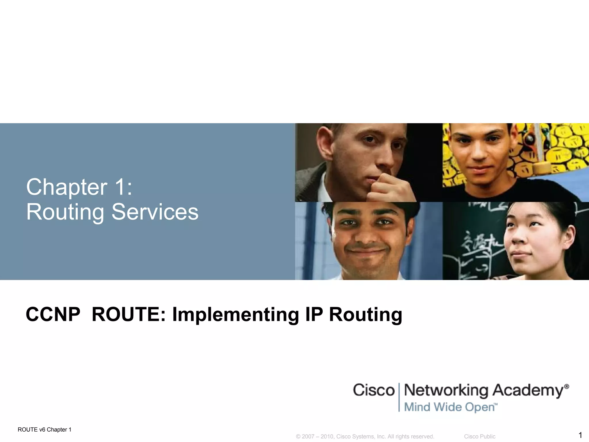
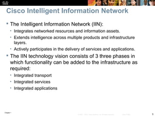
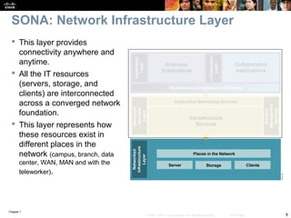
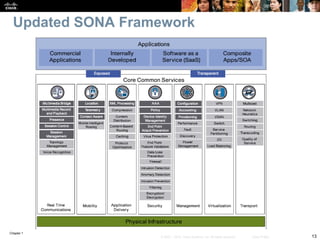
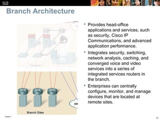
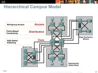
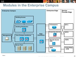
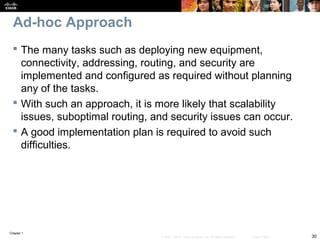
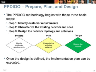
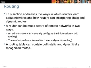
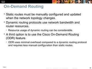
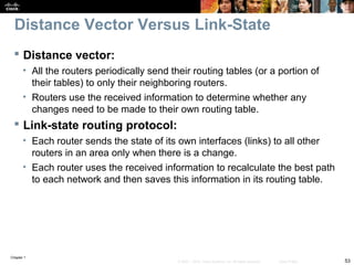
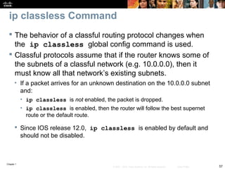
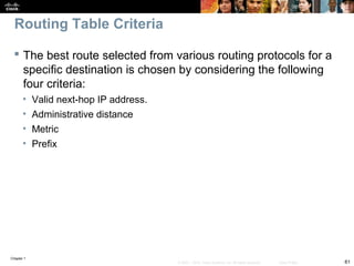
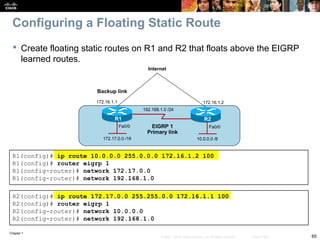
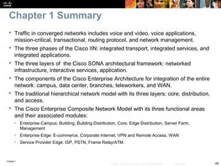
Configuring a Default Static Route
R2 is configured with a static route to the R1 LAN and a default static
route to the Internet.
R1 is configured with a default static route.
R1(config)# ip route 0.0.0.0 0.0.0.0 10.1.1.1
R1(config)# exit
R1# show ip route
<output omitted>
Gateway of last resort is not set
C 172.16.1.0 is directly connected, FastEthernet0/0
C 10.1.1.0 is directly connected, Serial0/0/0
S* 0.0.0.0/0 [1/0] via 10.1.1.1
R1#
R2(config)# ip route 172.16.1.0 255.255.255.0 S0/0/0
R2(config)# ip route 0.0.0.0 0.0.0.0 192.168.1.1
Internet
S0/0/0
S0/0/0
Fa0/0Fa0/0
10.1.1.2
10.1.1.1
192.168.1.2 192.168.1.1
S0/0/1
R1 R2
172.16.1.0 /24 10.2.0.0 /16](https://image.slidesharecdn.com/01-routeroutingservices-130516201606-phpapp01/85/01-route-routing-services-46-320.jpg)
![Chapter 1
51© 2007 – 2010, Cisco Systems, Inc. All rights reserved. Cisco Public
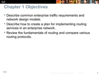
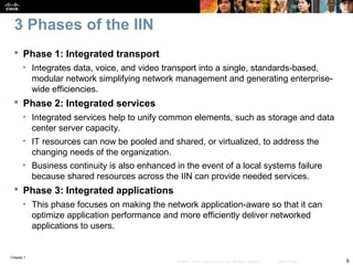
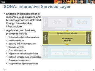
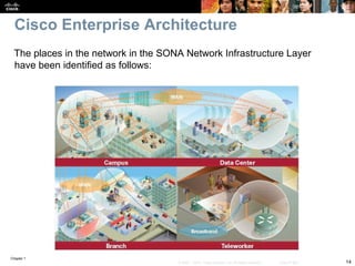
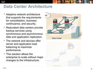
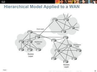
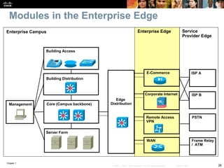
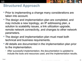
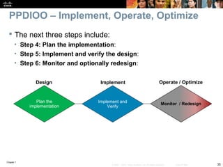
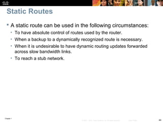
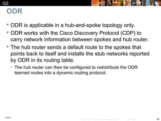
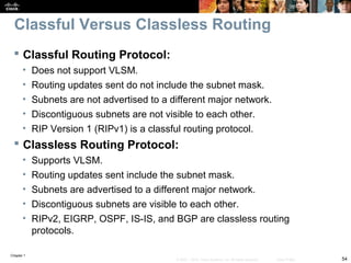
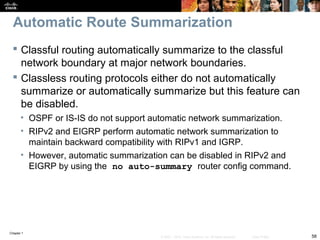
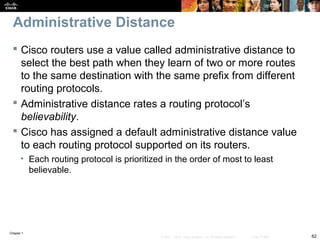
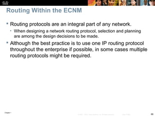
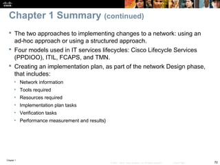
Configuring ODR
R1 is a hub router while R2 and R3 are stub routers.
All routers have CDP enabled.
R1(config)# router odr
R1(config)# exit
R1# show ip route
<output omitted>
172.16.0.0/16 is subnetted, 2 subnets
o 172.16.1.0/24 [160/1] via 10.1.1.2, 00:00:23, Serial0/0/1
o 172.16.2.0/24 [160/1] via 10.2.2.2, 00:00:03, Serial0/0/2
<output omitted>
R1#
S0/0/1
10.1.1.2
S0/0/2
R2 R1
172.16.1.0 /24
R3
172.16.2.0 /24
10.2.2.2
10.2.2.110.1.1.1](https://image.slidesharecdn.com/01-routeroutingservices-130516201606-phpapp01/85/01-route-routing-services-51-320.jpg)

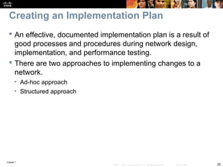
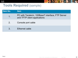
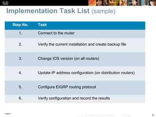
The document discusses network design models and frameworks including the Cisco Intelligent Information Network (IIN), Service-Oriented Network Architecture (SONA), and Enterprise Composite Network Model. It also covers creating an effective implementation plan using a structured approach and Cisco's PPDIOO model of Prepare, Plan, Design, Implement, Operate, and Optimize phases. Sample sections of an implementation plan are provided such as a project contact list, equipment floor plan, tools required, and task list.


