
Recommended
More Related Content
What's hot
What's hot (20)
Similar to As friction welding converted
Similar to As friction welding converted (20)
More from sharmaabhi
Recently uploaded
Recently uploaded (20)
As friction welding converted
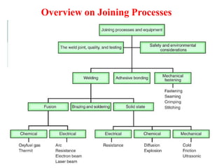
- 1. Overview on Joining Processes
- 2. Overview on Joining Processes Method (AWS A3.0:2001)
- 6. Fusion Welding Any welding process that uses fusion of the base metal to make the weld (AWS A3.0: 2001)
- 7. Fusion Welding – Arc Welding Arc Welding ⚫ ⚫ ⚫ ⚫ ⚫ ⚫ A fusion welding process in which coalescence of the metals is achieved by the heat from an electric arc between an electrode and the work Electric energy from the arc produces temperatures ~ 10,000 F (5500 C), hot enough to melt any metal Most AW processes add filler metal to increase volume and strength of weld joint An electric arc is a discharge of electric current across a gap in a circuit It is sustained by an ionized column of gas (plasma) through which the current flows To initiate the arc in AW, electrode is brought into contact with work and then quickly separated from it by a short distance
- 8. Figure 31.25 Thermit welding: (1) Thermit ignited; (2) crucible tapped, superheated metal flows into mold; (3) metal solidifies to produce weld joint. Fusion Welding - Thermit Welding (TW)
- 9. Solid State Welding - Friction Welding (FRW) SSW process in which coalescence is achieved by frictional heat combined with pressure When properly carried out, no melting occurs at faying surfaces No filler metal, flux, or shielding gases normally used Process yields a narrow HAZ Can be used to join dissimilar metals Widely used commercial process, amenable to automation and mass production
- 10. Figure 31.28 Friction welding (FRW): (1) rotating part, no contact; (2) parts brought into contact to generate friction heat; (3) rotation stopped and axial pressure applied; and (4) weld created. Solid State Welding - Friction Welding (FRW)
- 11. Solid State Welding - Friction Welding (FRW) 1. Two Types of Friction Welding Continuous-drive friction welding ⚫ ⚫ One part is driven at constant rpm against stationary part to cause friction heat at interface At proper temperature, rotation is stopped and parts are forced together 2. Inertia friction welding ⚫ ⚫ Rotating part is connected to flywheel, which is brought up to required speed Flywheel is disengaged from drive, and parts are forced together
- 12. Solid State Welding - Friction Welding (FRW) Applications: Shafts and tubular parts Industries: automotive, aircraft, farm equipment, petroleum and natural gas Limitations: At least one of the parts must be rotational Flash must usually be removed Upsetting reduces the part lengths (which must be taken into consideration in product design)
- 13. 1. 2. 3. BRAZING, SOLDERING, AND ADHESIVE BONDING Brazing Soldering Adhesive Bonding
- 14. Overview of Brazing and Soldering Both use filler metals to permanently join metal parts, but there is no melting of base metals When to use brazing or soldering instead of fusion welding: ⚫ Metals have poor weldability ⚫ Dissimilar metals are to be joined ⚫ Intense heat of welding may damage components being joined ⚫ Geometry of joint not suitable for welding ⚫ High strength is not required
- 15. Overview of Adhesive Bonding Uses forces of attachment between a filler material and two closely-spaced surfaces to bond the parts ⚫ Filler material in adhesive bonding is not metallic ⚫ Joining process can be carried out at room temperature or only modestly above
- 16. Brazing Joining process in which a filler metal is melted and distributed by capillary action between faying surfaces of metal parts being joined No melting of base metals occurs ⚫ Only the filler melts Filler metal Tm greater than 450C (840F) but less than Tm of base metal(s) to be joined
- 17. Strength of Brazed Joint If joint is properly designed and brazing operation is properly performed, solidified joint will be stronger than filler metal out of which it was formed Why? ⚫ Small part clearances used in brazing ⚫ Metallurgical bonding that occurs between base and filler metals ⚫ Geometric constrictions imposed on joint by base parts
- 18. Brazing Compared to Welding Any metals can be joined, including dissimilar metals Can be performed quickly and consistently, permitting high production rates Multiple joints can be brazed simultaneously Less heat and power required than FW Problems with HAZ in base metal are reduced Joint areas that are inaccessible by many welding processes can be brazed; capillary action draws molten filler metal into joint
- 19. Disadvantages and Limitations of Brazing Joint strength is generally less than a welded joint Joint strength is likely to be less than the base metals High service temperatures may weaken a brazed joint Color of brazing metal may not match color of base metal parts, a possible aesthetic disadvantage
- 20. Brazing Applications Automotive (e.g., joining tubes and pipes) Electrical equipment (e.g., joining wires and cables) Cutting tools (e.g., brazing cemented carbide inserts to shanks) Jewelry Chemical process industry Plumbing and heating contractors join metal pipes and tubes by brazing Repair and maintenance work
- 21. Brazed Joints Butt and lap joints common ⚫ Geometry of butt joints is usually adapted for brazing ⚫ Lap joints are more widely used, since they provide larger interface area between parts Filler metal in a brazed lap joint is bonded to base parts throughout entire interface area, rather than only at edges
- 22. Figure 32.1 (a) Conventional butt joint, and adaptations of the butt joint for brazing: (b) scarf joint, (c) stepped butt joint, (d) increased cross-section of the part at the joint. Butt Joints for Brazing
- 23. Figure 32.2 (a) Conventional lap joint, and adaptations of the lap joint for brazing: (b) cylindrical parts, (c) sandwiched parts, and (d) use of sleeve to convert butt joint into lap joint. Lap Joints for Brazing
- 24. Some Filler Metals for Brazing Base metal(s) Aluminum Nickel-copper alloy Copper Steel, cast iron Stainless steel Filler metal(s) Aluminum and silicon Copper Copper and phosphorous Copper and zinc Gold and silver
- 25. Desirable Brazing Metal Characteristics Melting temperature of filler metal is compatible with base metal Low surface tension in liquid phase for good wettability High fluidity for penetration into interface Capable of being brazed into a joint of adequate strength for application Avoid chemical and physical interactions with base metal (e.g., galvanic reaction)
- 26. Figure 32.4 Several techniques for applying filler metal in brazing: (a) torch and filler rod. Sequence: (1) before, and (2) after. Applying Filler Metal
- 27. Figure 32.4 Several techniques for applying filler metal in brazing: (b) ring of filler metal at entrance of gap. Sequence: (1) before, and (2) after. Applying Filler Metal
- 28. Brazing Fluxes Similar purpose as in welding; they dissolve, combine with, and otherwise inhibit formation of oxides and other unwanted byproducts in brazing process Characteristics of a good flux include: ⚫ Low melting temperature ⚫ Low viscosity so it can be displaced by filler metal ⚫ Facilitates wetting ⚫ Protects joint until solidification of filler metal
- 29. Heating Methods in Brazing Torch Brazing - torch directs flame against work in vicinity of joint Furnace Brazing - furnace supplies heat Induction Brazing – heating by electrical resistance to high-frequency current in work Resistance Brazing - heating by electrical resistance in parts Dip Brazing - molten salt or molten metal bath Infrared Brazing - uses high-intensity infrared lamp
- 30. Soldering Joining process in which a filler metal with Tm less than or equal to 450C (840F) is melted and distributed by capillary action between faying surfaces of metal parts being joined No melting of base metals, but filler metal wets and combines with base metal to form metallurgical bond Soldering similar to brazing, and many of the same heating methods are used Filler metal called solder Most closely associated with electrical and electronics assembly (wire soldering)
- 31. Soldering Advantages / Disadvantages Advantages: Lower energy than brazing or fusion welding Variety of heating methods available Good electrical and thermal conductivity in joint Easy repair and rework Disadvantages: Low joint strength unless reinforced by mechanically means Possible weakening or melting of joint in elevated temperature service
- 32. Filler metal / Solder Usually alloys of tin (Sn) and lead (Pb). Both metals have low Tm Lead is poisonous and its percentage is minimized in most solders Tin is chemically active at soldering temperatures and promotes wetting action for successful joining In soldering copper, copper and tin form intermetallic compounds that strengthen bond Silver and antimony also used in soldering alloys
- 33. Figure 32.8 Techniques for securing the joint by mechanical means prior to soldering in electrical connections: (a) crimped lead wire on PC board; (b) plated through-hole on PC board to maximize solder contact surface; (c) hooked wire on flat terminal; and (d) twisted wires. Mechanical Means to Secure Joint
- 34. Functions of Soldering Fluxes Be molten at soldering temperatures Remove oxide films and tarnish from base part surfaces Prevent oxidation during heating Promote wetting of faying surfaces Be readily displaced by molten solder during process Leave residue that is non-corrosive and nonconductive
- 35. Soldering Methods Many soldering methods same as for brazing, except less heat and lower temperatures are required Additional methods: ⚫ Hand soldering – manually operated soldering gun ⚫ ⚫ Wave soldering – soldering of multiple lead wires in printed circuit cards Reflow soldering –used for surface mount components on printed circuit cards
- 36. Figure 32.9 Wave soldering, in which molten solder is delivered up through a narrow slot onto the underside of a printed circuit board to connect the component lead wires. Wave Soldering
- 37. Adhesive Bonding Joining process in which a filler material is used to hold two (or more) closely-spaced parts together by surface attachment Used in a wide range of bonding and sealing applications for joining similar and dissimilar materials such as metals, plastics, ceramics, wood, paper, and cardboard Considered a growth area because of opportunities for increased applications
- 38. Adhesive Bonding - Terminology Adhesive = filler material, nonmetallic, usually a polymer Adherends = parts being joined Structural adhesives – of greatest interest in engineering, capable of forming strong, permanent joints between strong, rigid adherends
- 39. Curing in Adhesive Bonding Process by which physical properties of the adhesive are changed from liquid to solid, usually by chemical reaction, to accomplish surface attachment of parts Curing often aided by heat and/or a catalyst ⚫ If heat used, temperatures are relatively low Curing takes time - a disadvantage in production Pressure sometimes applied between parts to activate bonding process
- 40. Adhesive Bonding - Joint Strength Depends on strength of: ⚫ Adhesive ⚫ Attachment between adhesive and adherends Attachment mechanisms: ⚫ Chemical bonding – adhesive and adherend form primary bond on curing ⚫ Physical interactions - secondary bonding forces between surface atoms ⚫ Mechanical interlocking - roughness of adherend causes adhesive to become entangled in surface asperities
- 41. Adhesive Bonding - Joint Design Adhesive joints are not as strong as welded, brazed, or soldered joints Joint contact area should be maximized Adhesive joints are strongest in shear and tension ⚫ Joints should be designed so applied stresses are of these types Adhesive bonded joints are weakest in cleavage or peeling ⚫ Joints should be designed to avoid these types of stresses
- 42. Figure 32.10 Types of stresses that must be considered in adhesive bonded joints: (a) tension, (b) shear, (c) cleavage, and (d) peeling. Types of Stresses in Adhesive Bonding
- 43. Figure 32.11 Some joint designs for adhesive bonding: (a) through (d) butt joints; (e) through (f) T-joints; (b) and (g) through (j) corner joints. Joint Designs in Adhesive Bonding
- 44. Adhesive Types Natural adhesives - derived from natural sources, including gums, starch, dextrin, soya flour, collagen ⚫ Low-stress applications: cardboard cartons, furniture, bookbinding, plywood Inorganic - based principally on sodium silicate and magnesium oxychloride ⚫ Low cost, low strength Synthetic adhesives - various thermoplastic and thermosetting polymers
- 45. Synthetic Adhesives Most important category in manufacturing Synthetic adhesives cured by various mechanisms: ⚫ Mixing catalyst or reactive ingredient with polymer prior to applying ⚫ Heating to initiate chemical reaction ⚫ Radiation curing, such as UV light ⚫ Curing by evaporation of water ⚫ Application as films or pressure-sensitive coatings on surface of adherend
- 46. Applications of Adhesives Automotive, aircraft, building products, shipbuilding Packaging industries Footwear Furniture Bookbinding Electrical and electronics
- 47. Surface Preparation For adhesive bonding to succeed, part surfaces must be extremely clean Bond strength depends on degree of adhesion between adhesive and adherend, and this depends on cleanliness of surface ⚫ For metals, solvent wiping often used for cleaning, and abrading surface by sandblasting improves adhesion ⚫ For nonmetallic parts, surfaces are sometimes mechanically abraded or chemically etched to increase roughness