1. NAME: ST. RIOS RAMOS JUAN SEBASTIAN
DATE: 04/17/2022
DESIGN OF SUBSTRUCTURE ELEMENTS
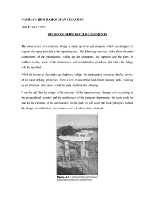
The substructure of a vehicular bridge is made up of several elements which are designed to
support the upper part that is the superstructure. The following summary talks about the main
components of the substructure, which are the abutments, the supports and the piers. In
addition to this, some of the maintenance and rehabilitation problems that affect the bridge
will be specified.
Of all the resources that make up a highway bridge, the replacement resources display several
of the most striking properties. Even a row of assembled land-based modular units, winding
up an abutment side slope, could be quite aesthetically pleasing.
It can be said that the design of the elements of the superstructure changes a lot according to
the geographical location and the preferences of the transport department, the same could be
true for the elements of the substructure. In this part, we will cover the basic principles behind
the design, rehabilitation, and maintenance of substructure elements.
2. Pillars:
The abutments are one of the very important elements of the structure, since they are located
at the end of a bridge and provide basic functions such as: support at the end of the first turn
or the last section, retaining the earth below and adjacent to the access road and supporting
part of the access roadway or access slab.
The abutment joint chosen for a given bridge depends on the geometry of the site, the size of
the composition, and the preferences of the owner. Simplifying, the bridge abutment can be
considered as a barricade equipped with a bridge seat.
Type of pillars:
With the barrier difference, most retaining wall systems, as long as they are equipped with a
bridge deck and made to withstand the severe loading conditions present in a bridge
construction highway, have the ability to be used as reinforcement. Another difference
between a typical retaining wall system and a pier is that this system is primarily equipped
with an adjacent flared wall.
Fin walls, like the ones shown in Figure 4.3, are awarded to help a pier confine the land
behind a pier. Once a subsequent wall, lateral wall, and footing make up a single structural
system, the study becomes quite difficult. In such a case, the designer has 2 possibilities
3. available, either to rely on a set of conservative assumptions and approximations or to use
PC-assisted resolutions, such as finite resource investigation.
A gravity pillar: it resists the horizontal pressure of the ground by its own dead weight.
Gravity piers are generally constructed of concrete; however, masonry is also sometimes
used. As explained above, a gravity shaker consists of a back wall and a side wall, tested
against the base.
U-Pillar: Since the side walls of a gravity pier are set at right angles to the next wall, the pier
is known as a U-Pier. The name "U-Pier" comes from the way the pillar once seen in plan.
Side walls are typically molded monolithically with the next wall of the pier and cantilevered
vertically from the footing. Several side walls also have the possibility of having a horizontal
cantilevered section.
Cantilever Abutment: A cantilever abutment is essentially the same as a cantilever retaining
wall (i.e., a wall or log that extends upward from the base), except that the cantilever
abutment is designed to carry higher vertical loads and is equipped with the bridge platform.
When a pillar has a large retaining wall or back wall connected to the adjacent side walls, the
structure is known as a U-pillar. The name is derived from the “U” shape of the pillar as seen
on the plans. The built abutment still has the formwork intact. Formwork is a complete system
4. of formwork, support, and related components that work together as a formwork for a
concrete element until the piece has sufficient strength to support itself, sometimes the
formwork. Prefabricated formwork is reusable, so this type of formwork is called formwork.
Full-height abutment: A full-elevation abutment is an abutment cantilever that extends from
the grade of the underpass (either roadway or body of water) to the grade of the overpass of
the preeminent roadway.
short pillar. Abutment is a relatively short abutment placed on an embankment or sloped
roof. Unless there is sufficient rock on the site, the piers are usually supported by pilings that
extend over the embankment.
Buttress/off-buttress abutment – Similar to a buttress retaining barrier, it uses a shaft and
footing that is braced with thin vertical slabs, known as buttresses, which remain spaced at
intervals.
Spill Pillar: Spill pillar uses 2 or more vertical columns or buttresses that have a cap beam
above them. The preeminent beam is used in parallel to support the bridge seat on which the
superstructure rests. The fill extends from the bottom of the head beam and is allowed to pass
through the open spaces in the middle of the vertical columns so that the abutment retains
only a section of the embankment.
A counterforti retaining barrier, such as the one illustrated in Figure 4.5, is primarily not
economically likely unless the elevation from the bottom of the footing to the crest of the
stem is greater than 20 to 25 feet (6.1 to 7.6m). The spacing between the buttresses is
established through trial and error with one obvious limiting constraint being price. Mainly,
a spot about one-third to one-half the elevation is more economical.
5. In the case of piers, the structure must be designed to withstand both the earth pressure and
the loads acting from the superstructure. Many factors influence the design process, including
the type of existing soil, drainage, and seismic loads. As for the second part, more details will
be presented in section 4.1.7. However, before discussing the seismic design of a pier, it is
necessary to review the fundamentals of Coulomb Carth 's pressure theory. The seismic
analysis used is an extension of the fundamentals described in this section. Figure 4.6
illustrates the basic forces acting on the column (seismic forces are also included in the
diagram and will be discussed later). The main force acting on an agitator is the applied
ground pressure, denoted by the variable P in Figure 4.6. The triangular arc defined by the
slope from the heel/toe to the top of the embankment is called the fault wedge. Coulomb's
theory is based on the following assumptions:
The soil is isotropic and homogeneous.
The soil has internal friction and cohesion.
The rupture surface is a flat surface.
6. The frictional forces are evenly distributed along the flat surface of rupture.
The fault wedge is a rigid body.
One of the main deficiencies with Coulomb's theory of earth pressure is that it assumes an
ideal ground and that the area of separation is determined by a plane. Coulomb himself
recognized that the area of separation was curved, however, he made the decision to
substitute a plane for the curve as an approximation.
For the time in which it takes place and the stage of his career, Coulomb's approach is
remarkably analytical. Active and passive earth pressures represent the maximum and
minimum values that can be used to determine the size of a retaining wall or abutment based
on a trial and error method.
As we will see shortly, seismic analysis uses many of the same methods, with the only
difference being that horizontal and vertical measurements are combined. vertical
acceleration factor to take into account the effect of seismic movement.
7. Active Earth Pressure represents the minimum lateral earth pressure. Most piers are very
rigid and cannot move or rotate freely, so the actual earth pressure is greater than the active
earth pressure. To account for this, ASSHTO recommends using a so-called "test" subfloor.
When the service load design method is used, no load factors or performance factors are
applied. Instead, a minimum factor of safety (FS) is required. Earlier it was mentioned that a
column must be designed to provide security against failure due to overloading or slippage.
With respect to the first, the safety factor against overturning can be defined by the following
expression:
Pile of Something: Piles constantly have a chance to be found in areas that are highly sensitive
to erosion and research. This implies that many piles will be used in spaces that are likely to
be considered hard.
When steel piles (for example, H-shaped steel piles) are used, the damage can be repaired by
adding a part to the damaged parts. This is generally recommended for less severe damage
with up to 50% partial loss in smaller areas and less. Also, damaged steel piles can be
repainted. When steel piles are driven underwater, shoring is often the preferred method of
restoration. If the deteriorated segment of steel pile is located in a dry area or above ground
level, another method of repair is to connect the new section to the existing pile. Just like a
steel object, when exposed to moisture, the steel must have a protective coating to prevent
corrosion.
Springs:
The development of bridge piers parallels the rise of the new highway system. Previously,
the use of bridge pillars was limited to constructions that crossed rivers or railways. the need
for earthen piers to facilitate grade-separated highways increased dramatically.
The springs in Figure 4.7 integrate elastomeric bearings in which the prestressed concrete
superstructure is supported. Such subjectively thin bearings make for a visually smooth
8. transition from dock to superstructure. For most constructions, including steel and timber
bridges, concrete is the material of choice for the substructure elements. wood, they are also
applied for pier constructs (for example, a steel frame pier or wooden ridge support
composition).
Types of springs:
In the sidebar accompanying Figure 1.5, diagrams of several basic types of lighthouses are
presented. Like a wharf, a wharf has a wharf on which the superstructure is tested. In Figure
4.8, this pedestal consists of a hammerhead-shaped pile head, on which the individual
platforms are located. The supports are in turn placed on the bases on which the
superstructure is examined. So we can see that in Figure 4.8 this column is used to support
the superstructure formed by the five major chords.
9. Hammerhead:
Hammerhead docks are primarily found in urban settings as they are attractive and take up
minimal space, providing space for underground traffic. As mentioned above, hammerhead
columns are most attractive when placed in structures with relatively large clearance
requirements (although they have been incorporated with shorter clearances). Personal
transportation services generally maintain standards regarding the use of hammerhead
sharks. Hammerhead abutments are also an interesting solution when the structure is at an
angle, creating tight connections for underground traffic. Unlike sloping column piles (see
below), single column hammers provide a solution for a more open and flowing appearance,
especially in high traffic multi-structure settings.
10. bent column
A bent column pier, as its name suggests, consists of a head beam and supporting columns
in a frame-like composition. Column bent piers represent one of the most famous forms of
piers in use in highway bridges. This fame is an effect of the extensive use of bent piers
throughout the early development of the U.S. interstate system. Like hammerhead piers,
support columns have a choice of circular or rectangular cross-section, although the first is
much more recurrent. The use of bent column columns, such as hammerheads, should be
judicious. However, in dense urban interchanges, the extensive use of bent pillars in columns
can give way to a crowded image that generates a 'concrete jungle' impact.
Comprehensive
an integral pier has a pier cap to which the main members of the superstructure are rigidly
connected. This dock pipe is not at all common and is generally limited to special structures,
particularly where tight vertical space restrictions pose a problem.