SlideShare a Scribd company logo
1 of 35
HIGH RISE
STRUCTURAL SYSTEMS
PRESENTED BY :
• AKSHAY REVEKAR
• DURGESH PIPPAL.
MITS GWLIOR
INTRODUCTION AND DEFINITION
High rise is defined differently by different bodies.
Emporis standards-
“A multi-story structure between 35-
100 meters tall, or a building of
unknown height from 12-39 floors is
termed as high rise.
Building code of Hyderabad,India-
A high-rise building is one with four
floors or more, or one 15 meters or
more in height.
The International Conference on Fire
Safety –
"any structure where the height can
have a serious impact on evacuation“
Massachusetts, United States General
Laws –
A high-rise is being higher than 70 feet
(21 m).
BELT TRUSS SYSTEM
CORE TRUSSMEGA STUCTURE OUT-TRIGGER
TRUSS
SHANGHAI TOWER
Structural Loads
Wind LoadsSeismic Loads
• Gravity loads
– Dead loads
– Live loads
– Snow loads
• Lateral loads
– Wind loads
– Seismic loads
• Special load cases
– Impact loads
– Blast loads
• A type of rigid frame construction.
• The shear wall is in steel or concrete to provide greater lateral
rigidity. It is a wall where the entire material of the wall is employed
in the resistance of both horizontal and vertical loads.
• Is composed of braced panels (or shear panels) to counter the
effects of lateral load acting on a structure. Wind & earthquake loads
are the most common among the loads.
• For skyscrapers, as the size of the structure increases, so
does the size of the supporting wall. Shear walls tend to be used only
in conjunction with other support systems.
Shear wall system
FRAMED-TUBE STRUCTURES]
The lateral resistant of the framed-tube structures is provided by very
stiff moment-resistant frames that form a “tube” around the
perimeter
of the building.
The basic inefficiency of the frame system for reinforced concrete
buildings of more than 15 stories resulted in member proportions
of prohibitive size and structural material cost premium, and thus
such system were economically not viable.
The frames consist of 6-12 ft (2-4m) between centers, joined by deep
spandrel girders.
Gravity loading is shared between the tube and interior column or
walls.
When lateral loading acts, the perimeter frame aligned in the
direction of loading acts as the “webs” of the massive tube of the
cantilever, and those normal to the direction of the loading act as the
“flanges”.
The tube form was developed originally for building of rectangular
plan, and probably it’s most efficient use in that shape.
Dewitt chestnut
THE TRUSSED TUBE
The trussed tube system represents a classic
solution for a tube uniquely suited to the qualities
and character of structural steel.
Interconnect all exterior columns to form a rigid
box, which can resist lateral shears by axial in its
members rather than through flexure.
Introducing a minimum number of diagonals on
each façade and making the diagonal intersect at
the same point at the corner column.
The system is tubular in that the fascia diagonals
not only form a truss in the plane, but also
interact with the trusses on the perpendicular
faces to affect the tubular behavior. This creates
the x form between corner columns on each
façade.
Relatively broad column spacing can resulted
large clear spaces for windows, a particular
characteristic of steel buildings.
The façade diagonalization serves to equalize the
gravity loads of the exterior columns that give a
significant impact on the exterior architecture.
John Hancock
Center introduced
trussed tube design.
Recently the use of perimeter diagonals – thus
the term “DIAGRID” - for structural effectiveness
and lattice-like aesthetics has generated renewed
interest in architectural and structural designers
of tall buildings.
Introducing a minimum
number of diagonals on
each façade and
making the diagonal
intersect at the same point
at the corner column
The concept allows for wider
column spacing in the tubular
walls than would be possible
with only the exterior frame
tube form.
The spacing which make it
possible to place interior frame
lines without seriously
compromising interior space
planning.
The ability to modulate the
cells vertically can create a
powerful vocabulary for a
variety of dynamic shapes
therefore offers great latitude
in architectural planning of at
all building.
Burj Khalifa, Dubai.
Sears Tower, Chicago.
BUNDLED TUBE SYSTEM
TUBE-IN-TUBE SYSTEM
This variation of the framed tube
consists of an outer frame tube,
the “Hull,” together
with an internal elevator and
service core.
The Hull and core act jointly in
resisting both gravity and lateral
loading.
The outer framed tube and the
inner core interact horizontally as
the shear and flexural components
of a wall-frame structure, with the
benefit of increased lateral
stiffness.
The structural tube usually adopts
a highly dominant role because of
its much greater structural depth.
Lumbago Tatung Haji
Building, Kuala Lumpur
Construction materials
Advantages are:
 Plasticity
 Easily availability
 Easy in casting
 Non corrosive
 Can be cast in situ
Disadvantages are:
 Cost of form
 Dead weight
 Difficulty in pouring
CONCRETE:- cellular concrete of clay-gypsum &
invention of light weight concrete.
FERRO CONCRETE:-it is layer of fine mesh
saturated with cement.
GUNITE:- it is also known as shot Crete.
compressed air to shoot concrete onto
(or into) a frame or structure. Shot Crete is
frequently used against vertical soil or rock
surfaces, as it eliminates the need for
formwork.
GLASS:- float glass with double glass is used in tall
buildings .
Tempered glass is used in tall buildings instead
of plain glass, as that would shatter at such
height.
Materials used for high rise buildings: concrete, steel, glass, cladding material, high alumina
cement used for roofs & floors. It contains bauxite instead of clay, cement, Portland cement of
lime stone, silica.
• Raft foundation: one of the most common foundation. It is known for its load distributing
capability. With the usage of this type of foundation the enormous load of the building gets
distributed & helps the building stay upright and sturdy. Loads are transferred by raft into the
ground.
• Pile foundation: used for high rise construction. load
of building is distributed to the ground with the help
of piles. Transfer the loads into the ground with an
Adequate factor of safety.
• Combined raft-pile: is the hybrid of 2 foundation. It
Consists of both the pile and raft foundation. Useful
in marshy sandy soil that has low bearing capacity.
Foundation Types
CONSTUCTION METHODS AND TECHNIQUES
Slip forming, continuous poured, continuously formed, or slip form
construction is a construction method in which concrete is poured into
a continuously moving form. Slip forming is used for tall structures (such
as bridges, towers, buildings, and dams), as well as horizontal structures,
such as roadways. Slip forming enables continuous, non-interrupted,
cast-in-place "flawless" (i.e. no joints) concrete structures which have
superior performance characteristics to piecewise construction using
discrete form elements. Slip forming relies on the quick-setting
properties of concrete, and requires a balance between quick-setting
capacity and workability. Concrete needs to be workable enough to be
placed into the form and consolidated (via vibration), yet quick-setting
enough to emerge from the form with strength. This strength is needed
because the freshly set concrete must not only permit the form to "slip"
upwards but also support the freshly poured concrete above it.
In vertical slip forming the concrete form may be surrounded by a
platform on which workers stand, placing steel reinforcing rods into the
concrete and ensuring a smooth pour. Together, the concrete form and
working platform are raised by means of hydraulic jacks. Generally, the
slipform rises at a rate which permits the concrete to harden by the time
it emerges from the bottom of the form
SLIP FORM CONSTRUCTION
Slipforming is an economical, rapid and accurate method
of constructing reinforced concrete. At its most basic
level, slipforming is a type of movable formwork which is
slowly raised,
allowing the continuous extrusion of concrete.
CLIMB FORM CONSTRUCTION
is an economical, rapid and accurate method of
constructing reinforced concrete, or post-tensioned
concrete structures. At its most basic level, slipforming is
a type of movable formwork which is slowly raised,
allowing the continuous extrusion of concrete.
TABLE FORM/FLYING FORM
A table form/flying form is a large pre-assembled
formwork
and falsework unit, often forming a complete bay
of
suspended floor slab. It offers mobility and quick
installation
for construction projects with regular plan layouts
or long
repetitive structures, so is highly suitable for flat
slab, and
beam and slab layouts. It is routinely used for
residential flats, hotels, hostels, offices and
commercial buildings.
SYSTEM COLUMN FORMWORK
The column formwork systems now available are normally
modular in nature and allow quick assembly and erection
on-site while minimising labour and crane time. They
are available in steel, aluminium and even cardboard
(not reusable but recycled) and have a variety of internal
face surfaces depending on the concrete finish required.
Innovations have led to adjustable, reusable column forms
which can be clamped on-site to give different column sizes.
VERTICAL PANEL SYSTEMS
Crane-lifted panel systems are commonly used on
building sites to form vertical elements and usually
consist
of a steel frame with plywood, steel, plastic or
composite
facing material.
The systems are normally modular in nature,
assembly
times and labour costs are considerably lower than
traditional formwork methods with far fewer
components
required. They offer greater opportunities for reuse
for
different applications on site.
Panel systems are extremely flexible and the larger
crane-lifted versions can be used for constructing
standard
concrete walls, perimeter basement walls, columns
and in
conjunction with jump form climbing systems.
JUMP FORM SYSTEMS
Generally, jump form systems comprise the formwork and
working platforms for cleaning/fixing of the formwork,
steel
fixing and concreting. The formwork supports itself on the
concrete cast earlier so does not rely on support or access
from other parts of the building or permanent works.
Jump form, here taken to include systems often
described as climbing form, is suitable for construction
of multi-storey vertical concrete elements in high-rise
structures, such as shear walls, core walls, lift shafts, stair
shafts and bridge pylons. These are constructed in a
staged process. It is a highly productive system designed
to increase speed and efficiency while minimising labour
and crane time.
Systems are normally modular and can be joined to
form long lengths to suit varying construction geometries.
Three types of jump form are in general use:
TYPES OF JUMP FORM
Normal jump/climbing form –
units are individually
lifted off the structure and relocated at the next
construction level using a crane.
Guided-climbing jump form –
also uses a crane but
offers greater safety and control during lifting as units
remain anchored/guided by the structure.
Self-climbing jump form –
does not require a crane as
it climbs on rails up the building by means of
hydraulic
jacks, or by jacking the platforms off internal recesses
in the structure. It is possible to link the hydraulic
jacks and lift multiple units in a single operation.
TUNNEL FORM
Tunnel form is used to form
repetitive cellular structures,
and is widely recognised as a
modern innovation that
enables the construction of
horizontal and vertical
elements (walls and floors)
together.
Significant productivity benefits
have been
achieved by using tunnel form to
construct cellular
buildings such as hotels, low- and
high-rise housing,
hostels, student accommodation,
prison and barracks
accommodation.
THANK YOU !

More Related Content

What's hot

Bundled Tube Structural System
 Bundled Tube Structural System Bundled Tube Structural System
Bundled Tube Structural SystemUmer Farooq
 
High rise building study & report
High rise building study & reportHigh rise building study & report
High rise building study & reportMithu hossain
 
Case Study: High Rise Buildings
Case Study: High Rise BuildingsCase Study: High Rise Buildings
Case Study: High Rise BuildingsPrasad Thanthratey
 
Types of Gravitational Loads And Forces
Types of Gravitational Loads And ForcesTypes of Gravitational Loads And Forces
Types of Gravitational Loads And ForcesManvinder Kingra
 
High rise buildings for architects by Dr.-Eng. Moaid subh
High rise buildings for architects   by Dr.-Eng. Moaid subhHigh rise buildings for architects   by Dr.-Eng. Moaid subh
High rise buildings for architects by Dr.-Eng. Moaid subhmoaidsubh
 
High rise buildings
High rise buildingsHigh rise buildings
High rise buildingsAnas Adel
 
Design of tall buildings lecture-1-part-2-dr-shafiul-bari-sir
Design of tall buildings lecture-1-part-2-dr-shafiul-bari-sirDesign of tall buildings lecture-1-part-2-dr-shafiul-bari-sir
Design of tall buildings lecture-1-part-2-dr-shafiul-bari-sirjibonghosh
 
Show reviewing the standards issues n requirements for tall buildings.ppsx (1)
Show reviewing the standards issues n requirements for tall buildings.ppsx (1)Show reviewing the standards issues n requirements for tall buildings.ppsx (1)
Show reviewing the standards issues n requirements for tall buildings.ppsx (1)Sanjay Srivastava
 
High-rise structural systems
High-rise structural systemsHigh-rise structural systems
High-rise structural systemsAkshay Revekar
 
L5 Vertical Structure Pt 3
L5 Vertical Structure Pt 3L5 Vertical Structure Pt 3
L5 Vertical Structure Pt 3chuhonsan
 
structure, technology and materials of highrise buildings
structure, technology and materials of highrise buildingsstructure, technology and materials of highrise buildings
structure, technology and materials of highrise buildingsshahul130103
 
Technology materials of tall buildings highrise
Technology materials of tall buildings highriseTechnology materials of tall buildings highrise
Technology materials of tall buildings highriseBee Key Verma
 

What's hot (18)

Design highrise
Design highriseDesign highrise
Design highrise
 
Type of high rise building
Type of high rise buildingType of high rise building
Type of high rise building
 
Bundled Tube Structural System
 Bundled Tube Structural System Bundled Tube Structural System
Bundled Tube Structural System
 
rahul
rahulrahul
rahul
 
High rise building study & report
High rise building study & reportHigh rise building study & report
High rise building study & report
 
Case Study: High Rise Buildings
Case Study: High Rise BuildingsCase Study: High Rise Buildings
Case Study: High Rise Buildings
 
Types of Gravitational Loads And Forces
Types of Gravitational Loads And ForcesTypes of Gravitational Loads And Forces
Types of Gravitational Loads And Forces
 
kkr 2
kkr 2kkr 2
kkr 2
 
High rise buildings for architects by Dr.-Eng. Moaid subh
High rise buildings for architects   by Dr.-Eng. Moaid subhHigh rise buildings for architects   by Dr.-Eng. Moaid subh
High rise buildings for architects by Dr.-Eng. Moaid subh
 
High rise buildings
High rise buildingsHigh rise buildings
High rise buildings
 
Podium
PodiumPodium
Podium
 
Design of tall buildings lecture-1-part-2-dr-shafiul-bari-sir
Design of tall buildings lecture-1-part-2-dr-shafiul-bari-sirDesign of tall buildings lecture-1-part-2-dr-shafiul-bari-sir
Design of tall buildings lecture-1-part-2-dr-shafiul-bari-sir
 
Show reviewing the standards issues n requirements for tall buildings.ppsx (1)
Show reviewing the standards issues n requirements for tall buildings.ppsx (1)Show reviewing the standards issues n requirements for tall buildings.ppsx (1)
Show reviewing the standards issues n requirements for tall buildings.ppsx (1)
 
High-rise structural systems
High-rise structural systemsHigh-rise structural systems
High-rise structural systems
 
L5 Vertical Structure Pt 3
L5 Vertical Structure Pt 3L5 Vertical Structure Pt 3
L5 Vertical Structure Pt 3
 
High rise
High riseHigh rise
High rise
 
structure, technology and materials of highrise buildings
structure, technology and materials of highrise buildingsstructure, technology and materials of highrise buildings
structure, technology and materials of highrise buildings
 
Technology materials of tall buildings highrise
Technology materials of tall buildings highriseTechnology materials of tall buildings highrise
Technology materials of tall buildings highrise
 

Similar to Finalppthighrise 130504010636-phpapp02

(M AZHAR NUMANI-'B') ADVANCED STRUCTURAL SYSTEM1.pdf
(M AZHAR NUMANI-'B') ADVANCED STRUCTURAL SYSTEM1.pdf(M AZHAR NUMANI-'B') ADVANCED STRUCTURAL SYSTEM1.pdf
(M AZHAR NUMANI-'B') ADVANCED STRUCTURAL SYSTEM1.pdfMohdAzharNumaniShah
 
Final presentation by Akramul masum from southeast university bangladesh.
Final presentation by Akramul masum from southeast university bangladesh.Final presentation by Akramul masum from southeast university bangladesh.
Final presentation by Akramul masum from southeast university bangladesh.Integrated Design
 
Lecture 8 THigh Rise structures.pdf
Lecture 8 THigh Rise structures.pdfLecture 8 THigh Rise structures.pdf
Lecture 8 THigh Rise structures.pdfSALONIKAAHUJA1
 
Multi storey frames
Multi storey framesMulti storey frames
Multi storey framesLALITH KUMAR
 
designhighrise-171106164907.pptx
designhighrise-171106164907.pptxdesignhighrise-171106164907.pptx
designhighrise-171106164907.pptxFarhanullah46
 
CONSTRUCTION SYSTEMS FOR HIGH RISE AND LONG SPAN BUILDING.pdf
CONSTRUCTION SYSTEMS FOR HIGH RISE AND LONG SPAN BUILDING.pdfCONSTRUCTION SYSTEMS FOR HIGH RISE AND LONG SPAN BUILDING.pdf
CONSTRUCTION SYSTEMS FOR HIGH RISE AND LONG SPAN BUILDING.pdfdaynight6
 
CONSTRUCTION SYSTEMS FOR HIGH RISE AND LONG SPAN BUILDING.pdf
CONSTRUCTION SYSTEMS FOR HIGH RISE AND LONG SPAN BUILDING.pdfCONSTRUCTION SYSTEMS FOR HIGH RISE AND LONG SPAN BUILDING.pdf
CONSTRUCTION SYSTEMS FOR HIGH RISE AND LONG SPAN BUILDING.pdfdaynight6
 
Load analysis and structural consideration
Load analysis and structural considerationLoad analysis and structural consideration
Load analysis and structural considerationBee Key Verma
 
loadanalysisandstructuralconsideration-190126210125-1.pdf
loadanalysisandstructuralconsideration-190126210125-1.pdfloadanalysisandstructuralconsideration-190126210125-1.pdf
loadanalysisandstructuralconsideration-190126210125-1.pdfnileshsurti
 
PRECAST BUILDING SYSTEM
PRECAST BUILDING SYSTEMPRECAST BUILDING SYSTEM
PRECAST BUILDING SYSTEMSagar Shah
 
Precast construction
Precast constructionPrecast construction
Precast constructionDivya Vishnoi
 
Chapters-3,4,5.pptx
Chapters-3,4,5.pptxChapters-3,4,5.pptx
Chapters-3,4,5.pptxssuserc0bf9b
 
TUBE-STRUCTURES.ppt
TUBE-STRUCTURES.pptTUBE-STRUCTURES.ppt
TUBE-STRUCTURES.pptaliakmal13
 

Similar to Finalppthighrise 130504010636-phpapp02 (20)

TALL BUILDINGS
TALL BUILDINGSTALL BUILDINGS
TALL BUILDINGS
 
(M AZHAR NUMANI-'B') ADVANCED STRUCTURAL SYSTEM1.pdf
(M AZHAR NUMANI-'B') ADVANCED STRUCTURAL SYSTEM1.pdf(M AZHAR NUMANI-'B') ADVANCED STRUCTURAL SYSTEM1.pdf
(M AZHAR NUMANI-'B') ADVANCED STRUCTURAL SYSTEM1.pdf
 
Final presentation by Akramul masum from southeast university bangladesh.
Final presentation by Akramul masum from southeast university bangladesh.Final presentation by Akramul masum from southeast university bangladesh.
Final presentation by Akramul masum from southeast university bangladesh.
 
High rise building construction
High rise building constructionHigh rise building construction
High rise building construction
 
Lecture 8 THigh Rise structures.pdf
Lecture 8 THigh Rise structures.pdfLecture 8 THigh Rise structures.pdf
Lecture 8 THigh Rise structures.pdf
 
Multi storey frames
Multi storey framesMulti storey frames
Multi storey frames
 
designhighrise-171106164907.pptx
designhighrise-171106164907.pptxdesignhighrise-171106164907.pptx
designhighrise-171106164907.pptx
 
CONSTRUCTION SYSTEMS FOR HIGH RISE AND LONG SPAN BUILDING.pdf
CONSTRUCTION SYSTEMS FOR HIGH RISE AND LONG SPAN BUILDING.pdfCONSTRUCTION SYSTEMS FOR HIGH RISE AND LONG SPAN BUILDING.pdf
CONSTRUCTION SYSTEMS FOR HIGH RISE AND LONG SPAN BUILDING.pdf
 
CONSTRUCTION SYSTEMS FOR HIGH RISE AND LONG SPAN BUILDING.pdf
CONSTRUCTION SYSTEMS FOR HIGH RISE AND LONG SPAN BUILDING.pdfCONSTRUCTION SYSTEMS FOR HIGH RISE AND LONG SPAN BUILDING.pdf
CONSTRUCTION SYSTEMS FOR HIGH RISE AND LONG SPAN BUILDING.pdf
 
Framed structures
Framed structures Framed structures
Framed structures
 
Load analysis and structural consideration
Load analysis and structural considerationLoad analysis and structural consideration
Load analysis and structural consideration
 
Load analysis and structural consideration
Load analysis and structural considerationLoad analysis and structural consideration
Load analysis and structural consideration
 
loadanalysisandstructuralconsideration-190126210125-1.pdf
loadanalysisandstructuralconsideration-190126210125-1.pdfloadanalysisandstructuralconsideration-190126210125-1.pdf
loadanalysisandstructuralconsideration-190126210125-1.pdf
 
PRECAST BUILDING SYSTEM
PRECAST BUILDING SYSTEMPRECAST BUILDING SYSTEM
PRECAST BUILDING SYSTEM
 
Guida ARBED edifici alti
Guida ARBED edifici altiGuida ARBED edifici alti
Guida ARBED edifici alti
 
Tall buildings
Tall buildingsTall buildings
Tall buildings
 
Precast construction
Precast constructionPrecast construction
Precast construction
 
Chapters-3,4,5.pptx
Chapters-3,4,5.pptxChapters-3,4,5.pptx
Chapters-3,4,5.pptx
 
Tube structures
Tube structuresTube structures
Tube structures
 
TUBE-STRUCTURES.ppt
TUBE-STRUCTURES.pptTUBE-STRUCTURES.ppt
TUBE-STRUCTURES.ppt
 

Finalppthighrise 130504010636-phpapp02

  • 1. HIGH RISE STRUCTURAL SYSTEMS PRESENTED BY : • AKSHAY REVEKAR • DURGESH PIPPAL. MITS GWLIOR
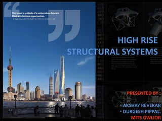
  • 2. INTRODUCTION AND DEFINITION High rise is defined differently by different bodies. Emporis standards- “A multi-story structure between 35- 100 meters tall, or a building of unknown height from 12-39 floors is termed as high rise. Building code of Hyderabad,India- A high-rise building is one with four floors or more, or one 15 meters or more in height. The International Conference on Fire Safety – "any structure where the height can have a serious impact on evacuation“ Massachusetts, United States General Laws – A high-rise is being higher than 70 feet (21 m).
  • 3.
  • 4.
  • 5.
  • 6.
  • 7.
  • 8.
  • 9.
  • 10.
  • 11.
  • 12.
  • 13.
  • 14.
  • 15.
  • 16.
  • 17. BELT TRUSS SYSTEM CORE TRUSSMEGA STUCTURE OUT-TRIGGER TRUSS SHANGHAI TOWER
  • 18. Structural Loads Wind LoadsSeismic Loads • Gravity loads – Dead loads – Live loads – Snow loads • Lateral loads – Wind loads – Seismic loads • Special load cases – Impact loads – Blast loads
  • 19. • A type of rigid frame construction. • The shear wall is in steel or concrete to provide greater lateral rigidity. It is a wall where the entire material of the wall is employed in the resistance of both horizontal and vertical loads. • Is composed of braced panels (or shear panels) to counter the effects of lateral load acting on a structure. Wind & earthquake loads are the most common among the loads. • For skyscrapers, as the size of the structure increases, so does the size of the supporting wall. Shear walls tend to be used only in conjunction with other support systems. Shear wall system
  • 20. FRAMED-TUBE STRUCTURES] The lateral resistant of the framed-tube structures is provided by very stiff moment-resistant frames that form a “tube” around the perimeter of the building. The basic inefficiency of the frame system for reinforced concrete buildings of more than 15 stories resulted in member proportions of prohibitive size and structural material cost premium, and thus such system were economically not viable. The frames consist of 6-12 ft (2-4m) between centers, joined by deep spandrel girders. Gravity loading is shared between the tube and interior column or walls. When lateral loading acts, the perimeter frame aligned in the direction of loading acts as the “webs” of the massive tube of the cantilever, and those normal to the direction of the loading act as the “flanges”. The tube form was developed originally for building of rectangular plan, and probably it’s most efficient use in that shape. Dewitt chestnut
  • 21. THE TRUSSED TUBE The trussed tube system represents a classic solution for a tube uniquely suited to the qualities and character of structural steel. Interconnect all exterior columns to form a rigid box, which can resist lateral shears by axial in its members rather than through flexure. Introducing a minimum number of diagonals on each façade and making the diagonal intersect at the same point at the corner column. The system is tubular in that the fascia diagonals not only form a truss in the plane, but also interact with the trusses on the perpendicular faces to affect the tubular behavior. This creates the x form between corner columns on each façade. Relatively broad column spacing can resulted large clear spaces for windows, a particular characteristic of steel buildings. The façade diagonalization serves to equalize the gravity loads of the exterior columns that give a significant impact on the exterior architecture. John Hancock Center introduced trussed tube design. Recently the use of perimeter diagonals – thus the term “DIAGRID” - for structural effectiveness and lattice-like aesthetics has generated renewed interest in architectural and structural designers of tall buildings. Introducing a minimum number of diagonals on each façade and making the diagonal intersect at the same point at the corner column
  • 22. The concept allows for wider column spacing in the tubular walls than would be possible with only the exterior frame tube form. The spacing which make it possible to place interior frame lines without seriously compromising interior space planning. The ability to modulate the cells vertically can create a powerful vocabulary for a variety of dynamic shapes therefore offers great latitude in architectural planning of at all building. Burj Khalifa, Dubai. Sears Tower, Chicago. BUNDLED TUBE SYSTEM
  • 23. TUBE-IN-TUBE SYSTEM This variation of the framed tube consists of an outer frame tube, the “Hull,” together with an internal elevator and service core. The Hull and core act jointly in resisting both gravity and lateral loading. The outer framed tube and the inner core interact horizontally as the shear and flexural components of a wall-frame structure, with the benefit of increased lateral stiffness. The structural tube usually adopts a highly dominant role because of its much greater structural depth. Lumbago Tatung Haji Building, Kuala Lumpur
  • 24. Construction materials Advantages are:  Plasticity  Easily availability  Easy in casting  Non corrosive  Can be cast in situ Disadvantages are:  Cost of form  Dead weight  Difficulty in pouring CONCRETE:- cellular concrete of clay-gypsum & invention of light weight concrete. FERRO CONCRETE:-it is layer of fine mesh saturated with cement. GUNITE:- it is also known as shot Crete. compressed air to shoot concrete onto (or into) a frame or structure. Shot Crete is frequently used against vertical soil or rock surfaces, as it eliminates the need for formwork. GLASS:- float glass with double glass is used in tall buildings . Tempered glass is used in tall buildings instead of plain glass, as that would shatter at such height. Materials used for high rise buildings: concrete, steel, glass, cladding material, high alumina cement used for roofs & floors. It contains bauxite instead of clay, cement, Portland cement of lime stone, silica.
  • 25. • Raft foundation: one of the most common foundation. It is known for its load distributing capability. With the usage of this type of foundation the enormous load of the building gets distributed & helps the building stay upright and sturdy. Loads are transferred by raft into the ground. • Pile foundation: used for high rise construction. load of building is distributed to the ground with the help of piles. Transfer the loads into the ground with an Adequate factor of safety. • Combined raft-pile: is the hybrid of 2 foundation. It Consists of both the pile and raft foundation. Useful in marshy sandy soil that has low bearing capacity. Foundation Types
  • 26. CONSTUCTION METHODS AND TECHNIQUES Slip forming, continuous poured, continuously formed, or slip form construction is a construction method in which concrete is poured into a continuously moving form. Slip forming is used for tall structures (such as bridges, towers, buildings, and dams), as well as horizontal structures, such as roadways. Slip forming enables continuous, non-interrupted, cast-in-place "flawless" (i.e. no joints) concrete structures which have superior performance characteristics to piecewise construction using discrete form elements. Slip forming relies on the quick-setting properties of concrete, and requires a balance between quick-setting capacity and workability. Concrete needs to be workable enough to be placed into the form and consolidated (via vibration), yet quick-setting enough to emerge from the form with strength. This strength is needed because the freshly set concrete must not only permit the form to "slip" upwards but also support the freshly poured concrete above it. In vertical slip forming the concrete form may be surrounded by a platform on which workers stand, placing steel reinforcing rods into the concrete and ensuring a smooth pour. Together, the concrete form and working platform are raised by means of hydraulic jacks. Generally, the slipform rises at a rate which permits the concrete to harden by the time it emerges from the bottom of the form
  • 27. SLIP FORM CONSTRUCTION Slipforming is an economical, rapid and accurate method of constructing reinforced concrete. At its most basic level, slipforming is a type of movable formwork which is slowly raised, allowing the continuous extrusion of concrete.
  • 28. CLIMB FORM CONSTRUCTION CLIMB FORM CONSTRUCTION is an economical, rapid and accurate method of constructing reinforced concrete, or post-tensioned concrete structures. At its most basic level, slipforming is a type of movable formwork which is slowly raised, allowing the continuous extrusion of concrete.
  • 29. TABLE FORM/FLYING FORM A table form/flying form is a large pre-assembled formwork and falsework unit, often forming a complete bay of suspended floor slab. It offers mobility and quick installation for construction projects with regular plan layouts or long repetitive structures, so is highly suitable for flat slab, and beam and slab layouts. It is routinely used for residential flats, hotels, hostels, offices and commercial buildings.
  • 30. SYSTEM COLUMN FORMWORK The column formwork systems now available are normally modular in nature and allow quick assembly and erection on-site while minimising labour and crane time. They are available in steel, aluminium and even cardboard (not reusable but recycled) and have a variety of internal face surfaces depending on the concrete finish required. Innovations have led to adjustable, reusable column forms which can be clamped on-site to give different column sizes.
  • 31. VERTICAL PANEL SYSTEMS Crane-lifted panel systems are commonly used on building sites to form vertical elements and usually consist of a steel frame with plywood, steel, plastic or composite facing material. The systems are normally modular in nature, assembly times and labour costs are considerably lower than traditional formwork methods with far fewer components required. They offer greater opportunities for reuse for different applications on site. Panel systems are extremely flexible and the larger crane-lifted versions can be used for constructing standard concrete walls, perimeter basement walls, columns and in conjunction with jump form climbing systems.
  • 32. JUMP FORM SYSTEMS Generally, jump form systems comprise the formwork and working platforms for cleaning/fixing of the formwork, steel fixing and concreting. The formwork supports itself on the concrete cast earlier so does not rely on support or access from other parts of the building or permanent works. Jump form, here taken to include systems often described as climbing form, is suitable for construction of multi-storey vertical concrete elements in high-rise structures, such as shear walls, core walls, lift shafts, stair shafts and bridge pylons. These are constructed in a staged process. It is a highly productive system designed to increase speed and efficiency while minimising labour and crane time. Systems are normally modular and can be joined to form long lengths to suit varying construction geometries. Three types of jump form are in general use:
  • 33. TYPES OF JUMP FORM Normal jump/climbing form – units are individually lifted off the structure and relocated at the next construction level using a crane. Guided-climbing jump form – also uses a crane but offers greater safety and control during lifting as units remain anchored/guided by the structure. Self-climbing jump form – does not require a crane as it climbs on rails up the building by means of hydraulic jacks, or by jacking the platforms off internal recesses in the structure. It is possible to link the hydraulic jacks and lift multiple units in a single operation.
  • 34. TUNNEL FORM Tunnel form is used to form repetitive cellular structures, and is widely recognised as a modern innovation that enables the construction of horizontal and vertical elements (walls and floors) together. Significant productivity benefits have been achieved by using tunnel form to construct cellular buildings such as hotels, low- and high-rise housing, hostels, student accommodation, prison and barracks accommodation.