File 1 proteus tutorial for digital circuit design
1. Digital Circuit Laboratory
Proteus Tutorial for Digital Circuit Design
Proteus is one of the most famous simulators. It can be uses to
simulate almost every circuit on electrical fields. It is easy to use
because of the GUI interface that is very similar to the real Prototype
board. Moreover, it can be used to design Print Circuit Board (PCB).
1. Objectives
1. Review students on using proteus software.
2. Introduce how to run simulation of designed digital circuit.
3. Understand how to applied digital logic equation to real hardware
designs
2. Tools and equipment specifications
Proteus sotware
3. Review topics:
1. Boolean algebra
2. Basic logic operation (for examples, and, or, not, and, etc.)
4. Related Theory
Proteus has many features to generate both analogue and digital
result. However, this lab will focus on only tools that will be used in digital
schematic designs.
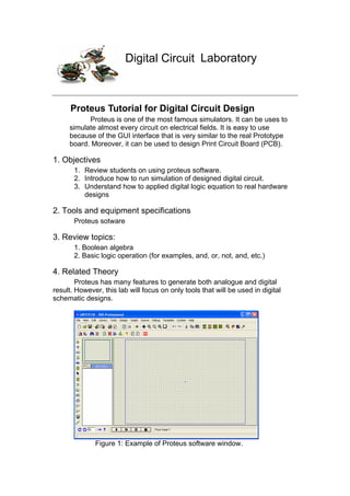
Figure 1: Example of Proteus software window.
2. Proteus that will be used in the lab is version 6.9 with service pack 9
can be called from Start>>Program>>Proteus 6 Professional>>ISIS 6
professional.
1. Proteus tools.
a. Parts Browsing
Proteus has many models of electronic equipments such as
logic gates, many kinds of switches and basic electronic devices.
These equipments can be founded by clicking on and then .
Then, a new window will pop up and wait for the part’s information as
shown in the Figure 2.
Figure 2 : Example of pick device page(1)
Finding Steps:
1. Type information of the device such as “and gate” in the box
1
2. If some specific category is known, the device can narrow on
focusing by selecting catalogue in the box 2
3. After the information is put, the list of the related devices will
appear in the box 3, so that needed device can be choose
here and then click “OK” button to confirm the selection as
shown in Figure 3.
3. Figure 3: Example of picking device page(2)
b. Power Supplies and input signal generators
All of the electrical circuits require power supplies. The power
supply for logic gates are represented in the digital system design on
proteus because the schematic will be too complicated to understand
for simulation section. Therefore, the power supplies will be need as
input power for a system. Moreover, all of the input generators, such as
ac, dc, and pulse, are contained in this category and it will be shown
when are clicked. Inaddition, “Ground” will not contain in this
groups because it is not input signal but it is just a terminal junction.
Therefore it will be group in the terminal ( ) category as shown in
Figure 5.
Figure 4 Figure 5
4. In addition, there is another input that usually be used in
digital circuit designed system but it does not exist in real world
as an equipment. It is called as “LOGIC STATE”. It can be find
in picking part section (typing “logicstate” and pick it.
Figure 6: logic state
2. How to do the simulating
a. Placing Equipments
After selecting all the devices, now devices needed to be placeb
on the circuit sheet (Grey sheet) and wiring before the simulation can be run
by following these steps:
1. Click on and select a first device that will be placed
2. Place mouse to wherever the device is preferred to be place and
then click the left button of the mouse. The device will be place. If it
needed to be moved. Click the right button of the mouse on the
device symbol to select the part and then hold the left button of the
mouse and move the symbol to wherever it is needed to be places.
Figure 7: placing the parts
5. 3. To wire the device together, click at the source pin of the device
and then move mouse cursor to the destination pin of the device. In
this step the pink line will be appear and it will be the wire of the
circuit after click mouse on the destination pin of the circuit (as
shown in figure 8)
Figure 8
4. After wiring all of the devices and all input together, the simulation is
ready to be run by clicking on to run and to stop.
However, to see the result measurements needed to be added in
the circuit. They will be explained in next part.
b. Measuring Digital data
Actually, the digital result on proteus can be seen in small
square at the pin of the equipments and the state will be shown in 4 colors
(red = logic “1”, Blue = logic ”0”, Grey = Unreadable logic and Yellow = Logic
congestion). However, proteus build a modules that can be used to show the
logic in 2 ways.
1. Logic display
The display that proteus has for seeing logic value is called
“logic-probe”. It has 2 sizes and these seizes have the same functions. And it
can be found from “picking devices” page
Figure 9 Logic Probe
6. 2. Waveform display.
In the low frequency case, logic-probe is the easiest way for
digital logic analysis because human eyes can see the result of the
simulation. Also, logic-probe also works for high frequency system but human
eyes can not see the results. Therefore, proteus create digital logic analyzer
for the high frequency jobs. To use the logic analyzer on proteus following
these steps.
1. Click on and place the voltage probe to the point the needed to
measure. After connect the probe to measured point, the probe will
be named as identifier of the measure point.
2. Click on and select “digital” from “Graphs” box then assign the
are of digital display. The Green screen will appear as
measurement monitor as shown in the figure 10
Figure 10 Example of digital analysis
3. Clicking at the word “DIGITAL ANALYSIS” on the screen. New
window will appear as the expanded screen as shown in figure 11.
Figure 11
7. 4. Click on graph>> add trace, new pop up window will appear to add
the measure points needed on “Probe P1” (if many probes appear
on the design, proteus may ask to offer all probes adding) then click
OK. The select probes will be added on the screen.
Figure 12
5. To see the result of the design, must be clicked to simulation
for 1 second.
Figure 13 Example of a digital circuit design
8. 4. Assignments
4.1 Create digital circuit from the equation below and write truth tables
a.
b.
c.
4.2 Compare the result of equation b and c from 4.2. Do they have the
same results? If so, show the Boolean algebra analysis to reduce the
equation from b to c. Gives the advantage of using Boolean algebra for the
circuit design.
4.3 Plot the relationship between all of the inputs and outputs of the
circuit diagram below
• Input X with 10kHz square wave or clock, Input Y with 20kHz clock,
and Input Ci with 30kHz clock.
• Outputs are S and Co