SlideShare a Scribd company logo
1 of 17
Download to read offline
Verilog 1995, 2001, and
SystemVerilog 3.1
Languages for Embedded Systems
Prof. Stephen A. Edwards
Summer 2004
NCTU, Taiwan
The Verilog Language
Originally a modeling language for a very efficient
event-driven digital logic simulator
Later pushed into use as a specification language for logic
synthesis
Now, one of the two most commonly-used languages in
digital hardware design (VHDL is the other)
Virtually every chip (FPGA, ASIC, etc.) is designed in part
using one of these two languages
Combines structural and behavioral modeling styles
Multiplexer Built From Primitives
module mux(f, a, b, sel); Verilog programs
built from modules
output f;
input a, b, sel;
Each module has
an interface
and g1(f1, a, nsel),
g2(f2, b, sel);
or g3(f, f1, f2);
not g4(nsel, sel); Module may contain
structure: instances of
primitives and other
modules
endmodule
g1
g4
g2
g3
a
b
sel
f
nsel
f1
f2
Multiplexer Built with Always
module mux(f, a, b, sel);
output f;
input a, b, sel;
reg f;
always
Modules may
contain one or more
always blocks
@(a or b or sel) Sensitivity list
contains signals
whose change
makes the block
execute
if (sel) f = a;
else f = b;
endmodule
a
b
sel
f
Multiplexer Built with Always
module mux(f, a, b, sel);
output f;
input a, b, sel;
reg f;
A reg behaves like
memory: holds its value
until imperatively
assigned otherwise
always @(a or b or sel)
if (sel) f = a;
else f = b;
Body of an always block
contains traditional
imperative code
endmodule
a
b
sel
f
Mux with Continuous Assignment
module mux(f, a, b, sel);
output f;
input a, b, sel;
assign
LHS is always set to
the value on the RHS
Any change on the right
causes reevaluation
f = sel ? a : b;
endmodule
a
b
sel
f
Mux with User-Defined Primitive
primitive mux(f, a, b, sel);
output f;
input a, b, sel;
table
1?0 : 1;
Behavior defined using
a truth table that
includes “don’t cares”
0?0 : 0;
?11 : 1;
?01 : 0;
11? : 1;
This is a less pessimistic than
others: when a & b match, sel is
ignored; others produce X
00? : 0;
endtable
endprimitive
a
b
sel
f
How Are Simulators Used?
Testbench generates stimulus and checks response
Coupled to model of the system
Pair is run simultaneously
Testbench System Model
Stimulus
Response
Result checker
Structural Modeling
When Verilog was first developed (1984) most logic
simulators operated on netlists
Netlist: list of gates and how they’re connected
A natural representation of a digital logic circuit
Not the most convenient way to express test benches
Behavioral Modeling
A much easier way to write testbenches
Also good for more abstract models of circuits
• Easier to write
• Simulates faster
More flexible
Provides sequencing
Verilog succeeded in part because it allowed both the
model and the testbench to be described together
How Verilog Is Used
Virtually every ASIC is designed using either Verilog or
VHDL (a similar language)
Behavioral modeling with some structural elements
“Synthesis subset” can be translated using Synopsys’
Design Compiler or others into a netlist
Design written in Verilog
Simulated to death to check functionality
Synthesized (netlist generated)
Static timing analysis to check timing
Two Main Components of Verilog:
Behavioral
Concurrent, event-triggered processes (behavioral)
Initial and Always blocks
Imperative code that can perform standard data
manipulation tasks (assignment, if-then, case)
Processes run until they delay for a period of time or wait
for a triggering event
Two Main Components of Verilog:
Structural
Structure (Plumbing)
Verilog program build from modules with I/O interfaces
Modules may contain instances of other modules
Modules contain local signals, etc.
Module configuration is static and all run concurrently
Two Main Data Types: Nets
Nets represent connections between things
Do not hold their value
Take their value from a driver such as a gate or other
module
Cannot be assigned in an initial or always block
Two Main Data Types: Regs
Regs represent data storage
Behave exactly like memory in a computer
Hold their value until explicitly assigned in an initial or
always block
Never connected to something
Can be used to model latches, flip-flops, etc., but do not
correspond exactly
Actually shared variables with all their attendant problems
Discrete-event Simulation
Basic idea: only do work when something changes
Centered around an event queue that contains events
labeled with the simulated time at which they are to be
executed
Basic simulation paradigm
• Execute every event for the current simulated time
• Doing this changes system state and may schedule
events in the future
• When there are no events left at the current time
instance, advance simulated time soonest event in the
queue
Four-valued Data
Verilog’s nets and registers hold four-valued data
0, 1: Obvious
Z: Output of an undriven tri-state driver. Models case
where nothing is setting a wire’s value
X: Models when the simulator can’t decide the value
• Initial state of registers
• When a wire is being driven to 0 and 1 simultaneously
• Output of a gate with Z inputs
Four-valued Logic
Logical operators work on three-valued logic
0 1 X Z
0 0 0 0 0
Outputs 0 if either
input is 0
1 0 1 X X
X 0 X X X Outputs X if both
inputs are gibberish
Z 0 X X X
Structural Modeling
Nets and Registers
Wires and registers can be bits, vectors, and arrays
wire a; // Simple wire
tri [15:0] dbus; // 16-bit tristate bus
tri #(5,4,8) b; // Wire with delay
reg [-1:4] vec; // Six-bit register
trireg (small) q; // Wire stores a small charge
integer imem[0:1023]; // Array of 1024 integers
reg [31:0] dcache[0:63]; // A 32-bit memory
Modules and Instances
Basic structure of a Verilog module:
module mymod(out1, out2,
Verilog convention
lists outputs first
in1, in2);
output out1;
output [3:0] out2;
input in1;
input [2:0] in2;
endmodule
Instantiating a Module
Instances of
module mymod(y, a, b);
look like
mymod mm1(y1, a1, b1); // Connect-by-position
mymod (y2, a1, b1),
(y3, a2, b2); // Instance names omitted
// Connect-by-name
mymod mm2(.a(a2), .b(b2), .y(c2));
Gate-level Primitives
Verilog provides the following:
and nand logical AND/NAND
or nor logical OR/NOR
xor xnor logical XOR/XNOR
buf not buffer/inverter
bufif0 notif0 Tristate with low enable
bifif1 notif1 Tristate with high enable
Delays on Primitive Instances
Instances of primitives may include delays
buf b1(a, b); // Zero delay
buf #3 b2(c, d); // Delay of 3
buf #(4,5) b3(e, f); // Rise=4, fall=5
buf #(3:4:5) b4(g, h); // Min-typ-max
Switch-level Primitives
Verilog also provides mechanisms for modeling CMOS
transistors that behave like switches
A more detailed modeling scheme that can catch some
additional electrical problems when transistors are used in
this way
Now, little-used because circuits generally aren’t built this
way
More seriously, model is not detailed enough to catch
many of the problems
These circuits are usually simulated using SPICE-like
simulators based on nonlinear differential equation solvers
User-Defined Primitives
Way to define gates and sequential elements using a truth
table
Often simulate faster than using expressions, collections
of primitive gates, etc.
Gives more control over behavior with X inputs
Most often used for specifying custom gate libraries
A Carry Primitive
primitive carry(out, a, b, c);
output out;
Always has exactly
one output
input a, b, c;
table
00? : 0;
0?0 : 0;
?00 : 0;
Truth table may include
don’t-care (?) entries
11? : 1;
1?1 : 1;
?11 : 1;
endtable
endprimitive
A Sequential Primitive
Primitive dff( q, clk, data);
output q; reg q;
input clk, data;
table
// clk data q new-q
(01) 0 : ? : 0; // Latch a 0
(01) 1 : ? : 1; // Latch a 1
(0x) 1 : 1 : 1; // Hold when d and q both 1
(0x) 0 : 0 : 0; // Hold when d and q both 0
(?0) ? : ? : -; // Hold when clk falls
? (??) : ? : -; // Hold when clk stable
endtable
endprimitive
Continuous Assignment
Another way to describe combinational function
Convenient for logical or datapath specifications
wire [8:0] sum; Define bus widths
wire [7:0] a, b;
wire carryin;
assign sum = a + b + carryin;
Continuous
assignment:
permanently
sets the value of
sum to be
a+b+carryin.
Recomputed
when a, b, or
carryin changes
Behavioral Modeling
Initial and Always Blocks
initial
begin
// imperative statements
end
Runs when simulation starts
Terminates when control
reaches the end
Good for providing stimulus
always
begin
// imperative statements
end
Runs when simulation starts
Restarts when control
reaches the end
Good for modeling or
specifying hardware
Initial and Always
Run until they encounter a delay
initial begin
#10 a = 1; b = 0;
#10 a = 0; b = 1;
end
or a wait for an event
always @(posedge clk) q = d;
always begin
wait(i);
a = 0;
wait( i);
a = 1;
end
Procedural Assignment
Inside an initial or always block:
sum = a + b + cin;
Just like in C: RHS evaluated and assigned to LHS before
next statement executes
RHS may contain wires and/or regs
LHS must be a reg
(only primitives or continuous assignment may set wire
values)
Imperative Statements
if (select == 1) y = a;
else y = b;
case (op)
2’b00: y = a + b;
2’b01: y = a - b;
2’b10: y = a ˆ b;
default: y = ’hxxxx;
endcase
For Loops
Example generates an increasing sequence of values on
an output
reg [3:0] i, output;
for ( i = 0 ; i <= 15 ; i = i + 1 ) begin
output = i;
#10;
end
While Loops
A increasing sequence of values on an output
reg [3:0] i, output;
i = 0;
while (i <= 15) begin
output = i;
#10 i = i + 1;
end
Modeling A Flip-Flop With Always
Very basic: an edge-sensitive flip-flop
reg q;
always @(posedge clk)
q = d;
q = d assignment runs when clock rises: exactly the
behavior you expect
Blocking vs. Nonblocking
Verilog has two types of procedural assignment
Fundamental problem:
• In a synchronous system, all flip-flops sample
simultaneously
• In Verilog, always @(posedge clk) blocks run in
some undefined sequence
A Flawed Shift Register
This does not work as you would expect:
reg d1, d2, d3, d4;
always @(posedge clk) d2 = d1;
always @(posedge clk) d3 = d2;
always @(posedge clk) d4 = d3;
These run in some order, but you don’t know which
Non-blocking Assignments
This version does work:
reg d1, d2, d3, d4;
always @(posedge clk) d2 <= d1;
Nonblocking rule:
RHS evaluated
when assignment
runs
always @(posedge clk) d3 <= d2;
always @(posedge clk) d4
LHS updated only
after all events for
the current instant
have run
<= d3;
Nonblocking Can Behave Oddly
A sequence of nonblocking assignments don’t
communicate
a = 1;
b = a;
c = b;
Blocking assignment:
a = b = c = 1
a <= 1;
b <= a;
c <= b;
Nonblocking assignment:
a = 1
b = old value of a
c = old value of b
Nonblocking Looks Like Latches
RHS of nonblocking taken from latches
RHS of blocking taken from wires
a = 1;
b = a;
c = b;
“1 c
a b
”
a <= 1;
b <= a;
c <= b;
“
1
c
a
b
”
Building Behavioral
Models
Modeling FSMs Behaviorally
There are many ways to do it:
• Define the next-state logic combinationally and define
the state-holding latches explicitly
• Define the behavior in a single always @(posedge
clk) block
• Variations on these themes
FSM with Combinational Logic
module FSM(o, a, b, reset);
output o;
reg o;
Output o is declared a reg
because it is assigned
procedurally, not because it
holds state
input a, b, reset;
reg [1:0] state, nextState;
always @(a or b or state)
case (state)
2’b00: begin
o = a & b;
nextState = a ? 2’b00 : 2’b01;
end
2’b01: begin
o = 0; nextState = 2’b10;
end
endcase
always @(posedge clk or reset)
if (reset)
state <= 2’b00;
else
state <= nextState;
endmodule
FSM with Combinational Logic
module FSM(o, a, b, reset);
output o;
reg o;
input a, b, reset;
reg [1:0] state, nextState;
always @(a or b or state)
Combinational block must be
sensitive to any change on any
of its inputs (Implies
state-holding elements
otherwise)
case (state)
2’b00: begin
o = a & b;
nextState = a ? 2’b00 : 2’b01;
end
2’b01: begin
o = 0; nextState = 2’b10;
end
endcase
always @(posedge clk or reset)
Latch implied by
sensitivity to the clock
or reset only
if (reset)
state <= 2’b00;
else
state <= nextState;
endmodule
FSM from a Single Always Block
module FSM(o, a, b);
output o; reg o;
input a, b;
reg [1:0] state;
always @(posedge clk or reset)
Expresses Moore
machine behavior:
Outputs are latched.
Inputs only sampled
at clock edges
if (reset) state <= 2’b00;
else case (state)
2’b00: begin
state <= a ? 2’b00 : 2’b01;
o <= a & b;
end
2’b01: begin
state <= 2’b10;
o <= 0;
Nonblocking assignments
used throughout to ensure
coherency. RHS refers to
values calculated in
previous clock cycle
end
endcase
Writing Testbenches
module test;
reg a, b, sel;
Inputs to device
under test
mux m(y, a, b, sel);
Device under test
initial begin
$monitor
$monitor is a built-in even-driven “printf”
($time,,"a=%b b=%b sel=%b y=%b",
a, b, sel, y);
a = 0; b= 0; sel = 0;
#10 a = 1;
#10 sel = 1;
Stimulus generated by
sequence of
assignments and
delays
#10 b = 1;
end
Simulating Verilog
Simulation Behavior
Scheduled using an event queue
Non-preemptive, no priorities
A process must explicitly request a context switch
Events at a particular time unordered
Scheduler runs each event at the current time, possibly
scheduling more as a result
Two Types of Events
Evaluation events compute functions of inputs
Update events change outputs
Split necessary for delays, nonblocking assignments, etc.
Update event writes
new value of a and
schedules any
evaluation events
that are sensitive to
a change on a
a <= b + c
Evaluation event
reads values of b
and c, adds them,
and schedules an
update event
Simulation Behavior
Concurrent processes (initial, always) run until they stop
at one of the following
• #42
Schedule process to resume 42 time units from now
• wait(cf & of)
Resume when expression “cf & of” becomes true
• @(a or b or y)
Resume when a, b, or y changes
• @(posedge clk)
Resume when clk changes from 0 to 1
Simulation Behavior
Infinite loops are possible and the simulator does not
check for them This runs forever: no context switch
allowed, so ready can never change
while (˜ready)
count = count + 1;
Instead, use
wait(ready);
Simulation Behavior
Race conditions abound in Verilog
These can execute in either order: final value of a
undefined:
always @(posedge clk) a = 0;
always @(posedge clk) a = 1;
Simulation Behavior
Semantics of the language closely tied to simulator
implementation
Context switching behavior convenient for simulation, not
always best way to model
Undefined execution order convenient for implementing
event queue
Compiled-Code Discrete-Event Sim.
Most modern simulators use this approach
Verilog program compiled into C
Each concurrent process (e.g., continuous assignment,
always block) becomes one or more C functions
Initial and always blocks split into multiple functions, one
per segment of code between a delay, a wait, or event
control (@)
Central, dynamic event queue invokes these functions and
advances simulation time
Verilog and Logic
Synthesis
Logic Synthesis
Verilog is used in two ways
Model for discrete-event simulation
Specification for a logic synthesis system
Logic synthesis converts a subset of the Verilog language
into an efficient netlist
One of the major breakthroughs in designing logic chips in
the last 20 years
Most chips are designed using at least some logic
synthesis
Logic Synthesis Tools
Mostly commercial tools
• Very difficult, complicated programs to write well
• Limited market
• Commercial products in $10k – $100k price range
Major vendors
• Synopsys Design Compiler, FPGA Express
• Cadence BuildGates
• Synplicity (FPGAs)
• Exemplar (FPGAs)
Academic tools
• SIS (UC Berkeley)
Logic Synthesis
Takes place in two stages:
1. Translation of Verilog (or VHDL) source to a netlist
Register inference performed here
2. Optimization of the resulting netlist to improve speed
and area
Most critical part of the process
Algorithms very complicated and beyond the scope of
this class
Logic Optimization
Netlist optimization the critical enabling technology
Takes a slow or large netlist and transforms it into one that
implements the same function more cheaply
Typical operations:
• Constant propagation
• Common subexpression elimination
• Function factoring
Time-consuming operation. Can take hours for large chips
Translating Verilog into Gates
Parts of the language easy to translate
Structural descriptions with primitives is already a netlist
Continuous assignment expressions turn into little
datapaths
Behavioral statements the bigger challenge
What Can Be Translated
Every structural definition
Behavioral blocks
• Depends on sensitivity list
• Only when they have reasonable interpretation as
combinational logic, edge, or level-sensitive latches
• Blocks sensitive to both edges of the clock, changes on
unrelated signals, changing sensitivity lists, etc. cannot be
synthesized
User-defined primitives
• Primitives defined with truth tables
• Some sequential UDPs can’t be translated (not latches or
flip-flops)
What Is Not Translated
Initial blocks
• Used to set up initial state or describe finite testbench stimuli
• Don’t have obvious hardware component
Delays
• May be in the Verilog source, but are simply ignored
A variety of other obscure language features
• In general, things heavily dependent on discrete-event
simulation semantics
• Certain “disable” statements
• Pure events
Register Inference
The main trick
A reg is not always a latch or flip-flop
Rule: Combinational if outputs always depend exclusively
on sensitivity list
Sequential if outputs may also depend on previous values
Register Inference
Combinational:
reg y;
always @(a or b or sel)
Sensitive to
changes on all the
variable it reads
if (sel) y = a;
else y = b; y is always assigned
Sequential:
reg q;
always @(d or clk)
if (clk) q = d;
q only assigned
when clk is 1
Register Inference
A common mistake is not completely specifying a case
statement
This implies a latch:
always @(a or b)
case ({a, b})
2’b00 : f = 0;
2’b01 : f = 1;
2’b10 : f = 1;
endcase
f is not assigned when
{a,b}= 2’b11
Register Inference
The solution is to always have a default case
always @(a or b)
case ({a, b})
2’b00 : f = 0;
2’b01 : f = 1;
2’b10 : f = 1;
default : f = 0; f is always assigned
endcase
Inferring Latches with Reset
Latches and Flip-flops often have reset inputs
Can be synchronous or asynchronous
Asynchronous positive reset:
always @(posedge clk or posedge reset)
if (reset)
q <= 0;
else q <= d;
Simulation-synthesis Mismatches
Many possible sources of conflict
• Synthesis ignores delays (e.g., #10), but simulation
behavior can be affected by them
• Simulator models X explicitly, synthesis does not
• Behaviors resulting from shared-variable-like behavior
of regs is not synthesized:
always @(posedge clk) a = 1;
New value of a may be seen by other @(posedge clk)
statements in simulation, never in synthesis
Summary of Verilog 1995
Systems described hierarchically
• Modules with interfaces
• Modules contain instances of primitives, other
modules
• Modules contain initial and always blocks
Based on discrete-event simulation semantics
• Concurrent processes with sensitivity lists
• Scheduler runs parts of these processes in response
to changes
Modeling Tools
Switch-level primitives: CMOS transistors as switches that
move around charge
Gate-level primitives: Boolean logic gates
User-defined primitives: Gates and sequential elements
defined with truth tables
Continuous assignment: Modeling combinational logic
with expressions
Initial and always blocks: Procedural modeling of behavior
Language Features
Nets (wires) for modeling interconnection
• Non state-holding
• Values set continuously
Regs for behavioral modeling
• Behave exactly like memory for imperative modeling
• Do not always correspond to memory elements in
synthesized netlist
Blocking vs. nonblocking assignment
• Blocking behaves like normal “C-like” assignment
• Nonblocking delays update, modeling synchronous
behavior
Language Uses
Event-driven simulation
• Event queue containing things to do at particular
simulated times
• Evaluate and update events
• Compiled-code event-driven simulation for speed
Logic synthesis
• Translating Verilog (structural and behavioral) into
netlists
• Register inference: whether output is always updated
• Logic optimization for cleaning up the result
Little-used Language Features
Switch-level modeling
• Much slower than gate or behavioral-level models
• Insufficient detail for modeling most electrical
problems
• Delicate electrical problems simulated with a
SPICE-like differential equation simulator
Little-used Language Features
Delays
• Simulating circuits with delays does not improve
confidence enough
• Hard to get timing models accurate enough
• Never sure you have simulated the worst case
• Static timing analysis has taken its place
Compared to VHDL
Verilog and VHDL are comparable languages
VHDL has a slightly wider scope
• System-level modeling
• Exposes even more discrete-event machinery
VHDL is better-behaved: Fewer sources of
nondeterminism (e.g., no shared variables)
VHDL is harder to simulate quickly
VHDL has fewer built-in facilities for hardware modeling
VHDL is a much more verbose language: Most examples
don’t fit on slides
In Conclusion
Verilog is a deeply flawed language
• Nondeterministic
• Often weird behavior due to discrete-event semantics
• Vaguely defined synthesis subset
• Many possible sources of simulation/synthesis
mismatch
In Conclusion
Verilog is widely used because it solves a problem
• Good simulation speed that continues to improve
• Designers use a well-behaved subset of the language
• Makes a reasonable specification language for logic
synthesis
• Logic synthesis one of the great design automation
success stories
Verilog 2001
Verilog 2001
Revised version of the Verilog language
IEEE Standard 1364-2001
Minor changes to the language:
ANSI C style ports
standard file I/O
(* attributes *)
multi dimensional arrays
generate
$value$plusargs
configurations
signed types
localparam
‘ifndef ‘elsif ‘line
memory part selects
automatic
constant functions
@*
variable part select
** (power operator)
Implicit event lists
Common mistake: forgetting a variable in combinational
sensitivity list
always @(a or b or c
Forgot to include d
)
f = a & b | c & d;
Does not simulate like hardware behaves.
Verilog 2001’s implicit sensitivity list:
always @*
f = a & b | c & d;
Makes process sensitive to all variables on right-hand side
of assignments.
Generate
Hardware structures often very regular. Want to create
them algorithmically.
Verilog’s generate: very clever macro expansion.
module gray2bin1 (bin, gray);
parameter SIZE = 8;
output [SIZE-1:0] bin;
input [SIZE-1:0] gray;
genvar i; // Compile-time only
generate for (i=0; i<SIZE; i=i+1)
begin:bit
assign bin[i] = ˆgray[SIZE-1:i];
end
endgenerate
endmodule
Attributes
Logic synthesis has relied on hints in comments:
always @(posedge clk)
begin
case (instr[6:5]) // synopsys full_case parallel_case
0 : mask <= 8’h01;
1 : mask <= 8’h02;
2 : mask <= 8’h04;
3 : mask <= 8’h08;
endcase
end
full_case means one case will always be true,
parallel_case means at most one will be true.
Can greatly simplify the generated logic, but
simulation/synthesis mismatch if assertion is not true.
Attributes
Such attributes now a first-class part of the language.
Simulator understands and checks validity.
always @(posedge clk)
begin
(* full_case, parallel_case=1 *)
case (instr[6:5])
0 : mask <= 8’h01;
1 : mask <= 8’h02;
2 : mask <= 8’h04;
3 : mask <= 8’h08;
endcase
end
ANSI C-style ports
Verilog 1995 ports could require three declarations:
module foo(myport1, myport2);
output myport1;
reg [7:0] myport1;
input [3:0] myport2;
...
endmodule
Verilog 2001 reduces this to one:
module foo(output reg [7:0] myport1,
input [3:0] myport2);
...
endmodule
Configurations
file lib.map
library gateLib ./*.vg;
library rtlLib *.v;
// specify rtl adder for top.a1
// gate-level adder for top.a2
config cfg1;
design rtlLib.top;
default liblist rtlLib;
instance top.a2
liblist gateLib;
endconfig
A way to select among different
implementations using the same
top-level modules.
file adder.v
module adder(...);
// RTL adder
// implementation
...
endmodule
file top.v
module top();
adder a1(...);
adder a2(...);
endmodule
file adder.vg
module adder(...);
// gate-level adder
...
endmodule
SystemVerilog
SystemVerilog
Much bigger change to the language.
Verification Features
assertions
biased random variables
test program blocks
process control
mailboxes
semaphores
clocking domains
direct C function calls
C++-like features
classes
dynamic arrays
inheritance
associative arrays
strings
references
More System Verilog Features
C-like features
int shortint
longint byte
shortreal void
alias enum
struct union
const typedef
break continue
return do while
casting
globals
++ --
+= -= *= /=
>>= <<= >>>= <<<=
&= |= ˆ= %=
Modeling Features
interfaces
dynamic processes
nested hierarchy
2-state modeling
unrestricted ports
packed arrays
implicit port connections
array assignments
enhanced literals
enhanced event control
time values & units
unique/priority case/if
logic-specific processes
root name space access
C-like Features
New Types
type values width new
reg { 0, 1, X, Z } 1+
logic { 0, 1, X, Z } 1+ ✓
integer { 0, 1, X, Z } 32
bit { 0, 1 } 1+ ✓
byte { 0, 1 } 8 ✓
shortint { 0, 1 } 16 ✓
int { 0, 1 } 32 ✓
longint { 0, 1 } 64 ✓
reg & logic now the same: both permit either continuous
or procedural assignment, but not both.
Other new types for two-valued functional simulation.
‘ifdef and typedef
Can define aliases for existing types. Useful, e.g., for
switching between four- and two-valued simulation:
‘ifdef TWOSTATE
typedef bit bit_t;
‘else
typedef logic bit_t;
‘endif
module dff (
output bit_t q,
input bit_t d, clk, rst);
always @(posedge clk)
if (rst) q <= 0;
else q <= d;
endmodule
Structs and Unions
SystemVerilog provides C-like structs and unions in both
packed and unpacked forms.
typedef struct {
logic PARITY;
logic[3:0] ADDR;
logic[3:0] DEST;
} pkt_t;
pkt_t mypkt;
mkpkt.ADDR = 12;
Packed vs. Unpacked
Structs are unpacked by default. The alignment of their
fields is implementation-dependent for efficiency, e.g.,
chosen by the C compiler.
typedef struct {
logic PARITY;
logic[3:0] ADDR;
logic[3:0] DEST;
} pkt_t;
31 3 1 0
PARITY
ADDR
DATA
Packed vs. Unpacked
Marking them packed removes padding: useful in unions.
typedef struct packed {
logic PARITY;
logic[3:0] ADDR;
logic[3:0] DEST;
} pkt_t;
8 5 4 1 0
DEST ADDR PARITY
Packed Structs and Unions
typedef struct packed {
logic [15:0] source_port;
logic [15:0] dest_port;
logic [31:0] sequence;
} tcp_t;
typedef struct packed {
logic [15:0] source_port;
logic [15:0] dest_port;
logic [15:0] length;
logic [15:0] checksum;
} udp_t;
typedef union packed {
tcp_t tcp_h;
udp_t udp_h;
bit [63:0] bits;
bit [7:0][7:0] bytes;
} ip_t;
ip_t ip_h;
logic parity;
// all are equivalent
ip_h.upd_h.length = 5;
ip_h.bits[31:16] = 5;
ip_h.bytes[3:2] = 5;
tcp_t source_port dest_port sequence
udp_t source_port dest_port length checksum
Operator Overloading
SystemVerilog provides operator overloading facilities like
those in C++ through the bind keyword.
typedef struct {
bit sign;
bit [3:0] exponent;
bit [10:0] mantissa;
}float;
bind + function float faddfr(float, real);
bind + function float faddff(float,
float);
float A, B, C, D;
assign A = B + C; // means A = faddff(B, C);
assign D = A + 1.0; // means A = faddfr(A, 1.0);
Classes
SystemVerilog provides C++-like classes with automatic
garbage collection.
class Packet;
bit [3:0] cmd;
int status;
header_t header;
function int get_status();
return status;
endfunction
extern task set_cmd(input bit [3:0] a);
endclass
task Packet::set_cmd(input bit [3:0] a);
cmd = a;
endtask
initial begin
Packet myPkt = new; // Create a new packet
end
Inheritance
As in C++, classes can inherit from other classes:
class ErrPkt extends Packet;
bit [3:0] err;
// New function
function bit [3:0] show_err;
return err;
endfunction
// Overrides Packet::set cmd
task set_cmd(input bit [3:0] a);
cmd = a + 1;
endtask
endclass
Packages
package ComplexPkg;
typedef struct {
float i, r;
} Complex;
function Complex add(Complex a, b);
add.r = a.r + b.r;
add.i = a.i + b.i;
endfunction
function Complex mul(Complex a, b);
mul.r = (a.r * b.r) + (a.i * b.i);
mul.i = (a.r * b.i) + (a.i * b.r);
endfunction
endpackage : ComplexPkg
module foo (input bit clk);
import ComplexPkg::*;
Complex a,b;
always @(posedge clk)
c = add(a,b);
endmodule
Hardware Modeling
Features
always comb, latch, and ff
In RTL design, a Verilog always block models
combinational logic, sequential logic driving flip-flops, or
sequential logic driving latches, never more than one.
SystemVerilog’s always comb, always ff, and always latch
keywords make the designer’s intent clear to the compiler
so it can issue error messages.
always comb, latch, and ff
// Probably intended combinational, but c becomes latch
always @(a or b)
if (b) c = a;
// Error: “missing else branch: c is not assigned”
always_comb
if (b) c = a;
// A correct level-sensitive latch
always_latch
if (clk)
if (en) q <= d;
// Error: “q always assigned: it is not a latch”
always_latch
q <= d
always comb, latch, and ff
Compiler verifies coding style.
// Correct edge-sensitive FF with asynchronous reset
always_ff @(posedge clk, negedge rst_n)
if (!rst_n) q <= 0;
else q <= d;
// Error: sensitivity not on edges
always_ff @(clk, rst_n)
if (!rst_n) q <= 0;
else q <= d;
// Error: combinational logic loop
always_latch
if (en) q <= d;
else q <= q; // Error
Unique/Priority
Verilog 1995 had no provision for checking uniqueness of
conditions: synthesis tools placed pragmas in comments.
Verilog 2001 added attributes for such conditions as
first-class entities.
SystemVerilog introduces new keywords implying unique
and complete conditions.
Cases must be Condition must be
complete unique
priority ✓
unique ✓ ✓
Priority Examples
// error if none of irq0–irq2 is true
priority case (1’b1)
irq0: irq = 3’b1 << 0;
irq1: irq = 3’b1 << 1;
irq2: irq = 3’b1 << 2;
endcase
// error if none of irq0–irq2 is true
priority if (irq0) irq = 3’b1;
else if (irq1) irq = 3’b2;
else if (irq2) irq = 3’b4;
// Default or else ignores priority
// This never raises an error:
priority if (irq0) irq = 3’b1;
else irq = 3’b0;
// Nor does this:
priority case (1’b1)
irq0: irq = 3’b1 << 0;
default: irq = 0;
endcase
Unique Examples
// Error if not exactly one of irq0–irq2 is true
unique case (1’b1)
irq0: irq = 3’b1 << 0;
irq1: irq = 3’b1 << 1;
irq2: irq = 3’b1 << 2;
endcase
// Error if not exactly one of irq0–irq2 is true
unique if (irq0) irq = 3’b1;
else if (irq1) irq = 3’b2;
else if (irq2) irq = 3’b4;
// Error if both irq0 and irq1 are true
unique if (irq0) irq = 3’b1;
else if (irq1) irq = 3’b2;
else irq = 3’b0;
// Error if both irq0 and irq1 are true:
unique case (1’b1)
irq0: irq = 3’b1 << 0;
irq1: irq = 3’b1 << 1;
default: irq = 0;
endcase
Implicitly-named ports
Hierarchy in Verilog usually for separating namespaces.
Net and port names typically common across modules.
Verbose in Verilog 1995:
module top;
wire [3:0] a;
wire [7:0] b;
wire [15:0] c;
foo foo1(a, b, c);
bar bar1(a, b, c);
endmodule
module foo(a, b, c);
input [3:0] a;
input [7:0] b;
input [15:0] c;
endmodule
module bar(a, b, c);
output a;
output b;
output c;
reg [3:0] a;
reg [7:0] b;
reg [15:0] c;
endmodule
Implicity-named Ports
Implicit ports plus ANSI-style declarations makes this
cleaner, especially for modules with many ports.
module top;
wire [3:0] a;
wire [7:0] b;
wire [15:0] c;
foo foo1(.*);
bar bar1(.*);
endmodule
module foo(
input [3:0] a,
input [7:0] b,
input [15:0] c);
endmodule
module bar(
output reg [3:0] a,
output reg [7:0] b,
output reg [15:0] c);
endmodule
Implicity-named Ports
Port renaming also supported. Allows specific ports to be
overridden or renamed as necessary.
module top;
wire [3:0] a;
wire [7:0] b;
wire [15:0] c;
foo foo1(.*);
bar bar1(.*, .other(c));
endmodule
module foo(
input [3:0] a,
input [7:0] b,
input [15:0] c);
endmodule
module bar(
output reg [3:0] a,
output reg [7:0] b,
output reg [15:0] other);
endmodule
Interfaces
For communication among modules. Like a collection of
shared variables.
interface simple_bus;
logic req, gnt;
logic [7:0] addr, data;
logic [1:0] mode;
logic start, rdy;
endinterface : simple_bus
module top;
logic clk = 0;
simple_bus mybus;
memory mem(mybus, clk);
cpu cpu(.b(mybus),
.clk(clk));
endmodule
module memory(
simple_bus a,
input bit clk);
always @(posedge clk)
a.gnt <= a.req & avail;
...
endmodule
module cpu(simple_bus b,
input bit clk);
...
endmodule
Interfaces with implicit ports
Even more simple. Use the same names and let the
compiler do the rest.
interface simple_bus;
logic req, gnt;
logic [7:0] addr, data;
logic [1:0] mode;
logic start, rdy;
endinterface : simple_bus
module top;
logic clk = 0;
simple_bus bus;
memory mem(.*);
cpu cpu(.*);
endmodule
module memory(
simple_bus bus,
input bit clk);
always @(posedge clk)
bus.gnt <= bus.req & av;
...
endmodule
module cpu(simple_bus bus,
input bit clk);
...
endmodule
Generic bundles
You can leave the exact type of an interface unspecified to
allow different implementations. Must connect explicitly.
interface simple_bus;
logic req, gnt;
logic [7:0] addr, data;
logic [1:0] mode;
logic start, rdy;
endinterface : simple_bus
module top;
logic clk = 0;
simple_bus bus;
memory mem(.*, .bus(bus));
cpu cpu(.*, .bus(bus));
endmodule
module memory(
interface bus,
input bit clk);
always @(posedge clk)
bus.gnt <= bus.req & av;
...
endmodule
module cpu(interface bus,
input bit clk);
...
endmodule
Ports on interfaces
Interfaces are groups of shared variables. Ports on
interfaces can bring connections in or out.
interface bus(
input bit clk,
output bit bus_error);
logic req, gnt;
logic [7:0] addr, data;
logic [1:0] mode;
logic start, rdy;
endinterface : bus
module top;
logic clk = 0, bus_error;
bus b(clk, bus_error);
memory mem(.*);
cpu cpu(.*);
endmodule
module memory(bus b);
always @(posedge b.clk)
b.gnt <= b.req & av;
...
endmodule
module cpu(bus b);
always @(posedge b.clk)
b.bus_error <=
cpu_error;
...
endmodule
Modports in interfaces
A way to constrain signal directions in interfaces.
interface bus(
input bit clk);
logic req, gnt, rdy;
logic [7:0] addr, data;
modport slave(
input req, addr, clk,
output gnt, rdy,
inout data);
modport master(
output req, addr,
input gnt, rdy, clk,
inout data)
endinterface : bus
module top;
logic clk = 0;
bus b(clk);
memory mem(.*);
cpu cpu(.*);
endmodule
module memory(bus.slave b);
always @(posedge bus.clk)
b.gnt <= b.req & av;
...
endmodule
module cpu(bus.master b);
...
endmodule
Tasks and Functions in Interfaces
interface bus;
logic start;
task slaveRead(
input logic[7:0] addr);
...
endtask: slaveRead
task masterRead(
input logic[7:0] addr);
...
endtask: masterRead
modport slave(
import task slaveRead(
input logic[7:0] addr);
);
endinterface: bus
module memory(interface b);
logic[7:0] addr;
always @(posedge b.clk)
b.slaveRead(addr);
endmodule
module omnip(interface b);
always @(posedge b.clk)
b.masterRead(addr);
always @(posedge b.clk)
b.slaveRead(addr);
endmodule
module top;
bus b;
// can invoke slaveRead only
memory m(b.slave);
// can use slaveRead, masterRead
omnip o(b);
endmodule
Dynamically-sized Arrays
Truly software-like behavior.
module dynamic_array;
bit[3:0] myarray[]; // Creates null reference
initial begin
myarray = new[4]; // Allocate four 4-bit words
// Double the size of the array, preserving its contents
myarray = new[myarray.size() * 2](myarray);
end
endmodule
Associative Arrays
Very abstract notion. Like maps in C++, hashtables in
Java, or associative arrays in Perl, Python, Awk.
module associative_array;
typedef struct packed {
int a;
logic [7:0] b;
} mykey_t;
int myarray[mykey_t]; // new, empty associative array
initial begin
mykey_t key1 = {-3, 8’xFE }; // structure literal
myarray[key1] = 10;
if (myarray.exists(key1))
myarray[key1] = -5;
myarray.delete(key1);
end
endmodule
Queues
Often used to communicate between processes.
module queues;
int q[$] = { 2, 4, 8 }; // initial contents
int sq[$:15]; // maximum size is 16
initial begin
int e = q[0]; // first item: 2
e = q[$]; // last item: 8
q = { q, 6 }; // append: now 2, 4, 8, 6
q = { e, q }; // insert: now 8, 2, 4, 8, 6
q = q[1:$]; // remove: now 2, 4, 8, 6
q = q[1:$-1]; // delete first, last: now 4, 8
end
endmodule
Process Management: join
Fork starts processes; join terminates when all blocks
terminate.
fork
begin
$display("0ns have elapsedn");
# 20ns; // delay
end
begin
# 20ns;
$display("20ns have elapsedn");
# 5ns;
end
join
# 5ns;
$display("30ns have elapsedn");
Process Management: join any
Fork starts processes; join any terminates when any of its
blocks terminate.
fork
begin
$display("0ns have elapsedn");
# 20ns; // delay
end
begin
# 20ns;
$display("20ns have elapsedn");
# 5ns;
end
join_any
# 5ns;
$display("25ns have elapsedn");
Process Management: join none
Fork starts processes; join none terminates immediately,
leaving its blocks running.
fork
begin
$display("0ns have elapsedn");
# 20ns; // delay
end
begin
# 20ns;
$display("20ns have elapsedn");
# 5ns;
end
join_none
# 5ns;
$display("5ns have elapsedn");
Process Management: wait fork
wait fork waits for all children to terminate.
task wait_fork_demo;
fork
task1(); // start task1 and task2 concurrently
task2();
join_any // terminates when either task1 or task2 does
fork
task3(); // start task3 and task4 concurrently
task4();
join_none;
// task3 and task4 and either task1 or task2 running
wait fork; // wait for all to complete
endtask
Process Management: disable fork
disable fork terminates all its children.
task wait_for_first( output int adr );
fork
wait_device( 1, adr); // user-defined task that waits
wait_device( 7, adr); // all three started concurrently
wait_device(13, adr);
join_any // terminate when one has arrived
disable fork; // terminate other two
Process control
task run_n_jobs_and_terminate_after_first(int N);
process job[1:N]; // The processes we spawn
for (int j = 1 ; j <= N ; j++)
fork
automatic int k = j; // for each job, k is its number
begin
job[j] = process::self(); // record who I am
... // the job itself
end
join_none // spawn next job immediately
for (int j = 1 ; j <= N ; j++)
wait( job[j] != null ); // wait for jobs to start
job[1].await(); // wait for first job to finish
for (int k = 1 ; k <= N ; k++ ) begin
if (job[k].status != process::FINISHED) // if not finished,
job[k].kill(); // kill it
end
endtask
Semaphores
Mutually-exclusive keys in a bucket. get blocks if not
enough keys are available.
semaphore we_are_there = new; // initialize with no keys
task drive;
fork
begin
# 100ns; // delay 100ns
we_are_there.put(1); // put a single key in the semaphore
end
begin
$display("Are we there yet?n");
we_are_there.get(1); // wait for a key
$display("We made itn");
end
join
endtask
Semaphores and events
event ask, answered;
semaphore answer = new;
int winner; // only valid after answer
task gameshow;
fork
begin // the host
-> ask; // Start the two contestants
answer.put(1); // let them compete
@answered; $display("%d was firstn", winner);
end
begin // contestant one
@ask; // wait for the question
think_about_answer(); answer.get(1); // try to answer first
winner = 1; -> answered; // signal our success
end
begin // contestant two
@ask;
think_about_answer(); answer.get(1);
winner = 2; -> answered;
end
join // Does this behave properly?
endtask
Mailboxes
Possibly bounded semaphore-like queues.
mailbox #(string) mybox = new(2); // capacity set to two
task mailbox_demo;
fork
begin
mybox.put("first letter");
$display("sent firstn");
mybox.put("second letter");
$display("sent secondn");
mybox.put("third letter");
$display("sent thirdn");
end
begin
$display("got %sn", mybox.get);
end
join
endtask
Prints
sent first
sent second
got first letter
got second letter
sent third
got third letter
Verification Features
Constrained Random Variables
Manually creating test cases tedious and difficult, yet
appears necessary for functional verification.
Current best practice: Constrained random tests.
SystemVerilog has features for creating such tests.
Constrained Random Variables
class Bus;
rand bit[15:0] addr;
rand bit[31:0] data;
constraint world_align { addr[1:0] = 2’b0; }
endclass
Bus bus = new;
repeat (50) begin
if (bus.randomize() == 1)
$display("addr = %16h data = %hn",
bus.addr, bus.data);
else
$display("overconstrained: no satisfying values
existn");
end
Adding constraints
class Bus;
rand bit[15:0] addr;
rand bit[31:0] data;
constraint world_align { addr[1:0] = 2’b0; }
endclass
Bus bus = new;
repeat (50) begin
if (bus.randomize() with { addr[31] == 0 } == 1)
$display("addr = %16h data = %hn",
bus.addr, bus.data);
else
$display("overconstrained: no satisfying values
existn");
end
Layering constraints
Constraints inherited, can be added in derived classes.
class Bus;
rand bit[15:0] addr;
rand bit[31:0] data;
constraint world_align { addr[1:0] = 2’b0; }
endclass
typdef enum { low, mid, high } AddrType;
class MyBus extends Bus;
rand AddrType atype; // Additional random variable
// Additional constraint on address: still word-aligned
constraint addr_range {
(atype == low ) -> addr inside { [0:15] };
(atype == mid ) -> addr inside { [16:127] };
(atype == high) -> addr inside { [128:255] };
}
endclass
Using Constraints
Very powerful constraint solving algorithm.
task exercise_bus;
int res;
// Restrict to low addresses
res = bus.randomize() with { atype == low; };
// Restrict to particular address range
res = bus.randomize()
with { 10 <= addr && addr <= 20 };
// Restrict data to powers of two
res = bus.randomize() with { data & (data - 1) == 0 };
// Disable word alignment
bus.word_align.constraint_mode(0);
res = bus.randomize with { addr[0] || addr[1] };
// Re-enable word alignment
bus.word_align.constraint_mode(1);
endtask
Other types of constraints
// Set membership constraints
rand integer x, y, z;
constraint c1 { x inside {3, 5, [9:15], [y:2*y], z}; }
integer fives[0:3] = { 5, 10, 15, 20 };
rand integer v;
constraint c2 { v inside fives; }
// Distribution constraints
rand integer w;
// make w 100 1/8 of time, 200 2/8, 300 5/8
constraint c3 { w dist {100 := 1, 200 := 2, 300 := 5 }; }
// Implication constraints
bit [3:0] a, b;
// force b to 1 when a is 0
constraint c4 { (a == 0) -> (b == 1); }
Many, many more features
Variables that step through random permutations (randc)
If-then-else constraints
Algorithmic constraints over array entries (foreach)
Constraints among multiple objects
Variable ordering constraints (solve..before)
Static constraints controlled by one constraint mode() call
Functions in constraints
Guarded constraints
pre- and post-randomize functions
Random variable disabling
Explicit randomization of arbitrary variables
Random sequence generation from a grammar
Coverage Checks
Once we have generated our tests, how good are they?
Current best practice: monitoring and improving coverage
Coverage: how many cases, statements, values, or
combinations have the test cases exercised?
Covergroup
Defines something whose coverage is to be checked.
Creates bins and tracks whether values ever appeared.
// color: a three-valued variable whose coverage is to be checked
enum { red, green, blue } color;
covergroup g1 @(posedge clk); // Sample at posedge clk
c: coverpoint color;
endgroup
g1 g1_inst = new; // Create the coverage object
At the end of simulation, reports whether color took all
three of its values.
Cross Coverage
May want to monitor combinations of variables.
enum { red, green, blue } color;
bit [3:0] pixel_adr, pixel_offset;
covergroup g2 @(posedge clk);
Hue: coverpoint pixel_hue;
Offset: coverpoint pixel_offset;
// Consider (color, pixel adr) pairs, e.g.,
// (red, 3’b000), (red, 3’b001), ..., (blue, 3’b111)
AxC: cross color, pixel_adr;
// Consider (color, pixel hue, pixel offset) triplets
// Creates 3 * 16 * 16 = 768 bins
all: cross color, Hue, Offset;
endgroup
g2 g2_inst = new; // Create a watcher
Covergroup in classes
Individual coverage of each object of a class.
class xyz;
bit [3:0] x;
int y;
bit z;
covergroup cov1 @z; // At every change of z,
coverpoint x; // sample x
coverpoint y; // and sample y.
endgroup
function new();
cov1 = new; // Create a watcher; variable cov1 implicit
endfunction
endclass
Predicated coverage
May want to selectively disable coverage:
covergroup g4 @(posedge clk);
// check s0 only if reset is true
coverpoint s0 iff(!reset);
endgroup
User-defined bins
May only want to track certain values of a variable.
bit [9:0] a; // Takes values 0–1023
covergroup cg @(posedge clk);
coverpoint a {
// place values 0–63 and 65 in bin a
bins a = { [0:63], 65 };
// create 65 bins, one for 127, 128, ..., 191
bins b[] = { [127:150], [148:191] };
// create three bins: 200, 201, and 202
bins c[] = { 200, 201, 202 };
// place values 1000–1023 in bin d
bins d = {[1000:$] };
// place all other values (e.g., 64, 66, .., 126, 192, ...) in their own bin
bins others[] = default;
}
endgroup
Covering Transitions
May want to check transitions, not just a variable’s values.
bit [3:0] a;
covergroup cg @(posedge clk);
coverpoint a {
// Place any of the sequences 4→5→6, 7→11, 8→11, 9→11, 10→11,
// 7→12, 8→12, 9→12, and 10→12 into bin sa.
bins sa = (4 => 5 => 6), ([7:9],10 => 11,12);
// Create separate bins for 4→5→6, 7→10, 8→10, and 9→10
bins sb[] = (4 => 5 => 6), ([7:9] => 10);
// Look for the sequence 3→3→3→3
bins sc = 3 [* 4];
// Look for any of the sequences 5→5, 5→5→5, or 5→5→5→5
bins sd = 5 [* 2:4];
// Look for any sequence of the form 6→· · ·→6→· · ·→6
// where “· · ·” represents any sequence that excludes 6
bins se = 6 [-> 3];
}
endgroup
Assertions
We have generated our tests, they do a reasonable job
covering the design, but how do we find problems?
Current best practice: Add assertions to the design that
check for unwanted conditions.
Currently, the most effective way to reduce debugging
time: bugs found more quickly, and easier to remedy.
Long used in software, growing use in hardware.
Main challenge in hardware: asserting temporal behavior.
SystemVerilog has constructs specifically for checking
sequences of things.
Immediate Assertions
Simplest assertions check an condition only when they
are executed.
// Make sure req1 or req2 is true if we are in the REQ state
always @(posedge clk)
if (state == REQ)
assert (req1 || req2);
// Same, but report the error ourselves
always @(posedge clk)
if (state == REQ)
assert (req1 || req2)
else
$error("In REQ; req1 || req2 failed (%0t)", $time);
Concurrent Assertions
Concurrent assertions check a property that spans time.
Data sampled at a clock and observed sequence checked.
For example, say we insist that ack must be asserted
between one and three cycles after req is asserted.
property req_ack;
@(posedge clk) // Sample req, ack at rising clock edge
// After req is true, between one and three cycles later,
// ack must have risen.
req ##[1:3] $rose(ack);
endproperty
// Assert that this property holds, i.e., create a checker
as_req_ack: assert property (req_ack);
Concurrent Assertions
Another example: make sure the address strobe is not
true for two consecutive cycles.
property no_two_astr;
@(posedge clk)
// Unless reset is true, make sure astr is
// not true for two cycles in a row.
disable iff (reset) not (astr [*2]);
endproperty
assert property (no_two_astr);
// Non-overlapping implication |=> waits a cycle
property no_two_astr2;
@(posedge clk)
disable iff (reset)
(astr |=> !astr); // When astr is true, astr is false next cycle.
endproperty
assert property (no_two_astr2);
Sequences and Properties
Sequences can be defined in isolation and used
elsewhere.
// The own bus signal goes high in 1 to 5 cycles,
// then the breq signal goes low one cycle later.
sequence own_then_release_breq;
##[1:5] own_bus ##1 !breq
endsequence
property legal_breq_handshake;
@(posedge clk) // On every clock,
disable iff (reset) // unless reset is true,
// once breq has risen, own bus should rise and breq should fall.
$rose(breq) |-> own_then_release_breq;
endproperty
assert property (legal_breq_handshake);
Sequences (partial syntax)
seq :=
expr Expression over signals
expr [* int-or-range ] Consecutive repetition
expr [= int-or-range ] Non-consecutive repetition
expr [-> int-or-range ] Goto repetition
seq ## int-or-range seq ... Delay between sequences
seq or seq Either true
seq and seq Both true
seq intersect seq Both true, end simultaneously
seq within seq Second starts/ends within first
Properties (partial syntax)
prop :=
seq Sequence
prop or prop Either holds
prop and prop Both hold
not prop Does not hold
seq |-> prop Prop holds when sequence ends
seq |=> prop Prop holds cycle after sequence ends
if ( expr ) prop
[ else prop ] If-then-else
SystemVerilog: Summary
Huge language that reflects changing design
methodologies:
Switch-level charge-transfer modeling (deprecated)
Gate-level structural modeling
RTL modeling
High-level software-like modeling
Assertions, random simulation, and coverage
Will it succeed?
Maybe.
Substantial industrial support (Cadence, Synopsys).
More of an incremental change than SystemC.
Reasonable, fairly clear, synthesizable subset.
Verilog, with all its flaws, has proven its worth.
Large language, but still fairly succinct.
Does it support the right set of methodologies?

More Related Content

Similar to Verilog_Cheat_sheet_1672542963.pdf

VIT_Workshop.ppt
VIT_Workshop.pptVIT_Workshop.ppt
VIT_Workshop.pptVINOTHRAJR1
 
Verilog Lecture4 2014
Verilog Lecture4 2014Verilog Lecture4 2014
Verilog Lecture4 2014Béo Tú
 
SKEL 4273 CAD with HDL Topic 2
SKEL 4273 CAD with HDL Topic 2SKEL 4273 CAD with HDL Topic 2
SKEL 4273 CAD with HDL Topic 2alhadi81
 
EMBEDDED SYSTEMS 4&5
EMBEDDED SYSTEMS 4&5EMBEDDED SYSTEMS 4&5
EMBEDDED SYSTEMS 4&5PRADEEP
 
Advanced Digital Design With The Verilog HDL
Advanced Digital Design With The Verilog HDLAdvanced Digital Design With The Verilog HDL
Advanced Digital Design With The Verilog HDLTony Lisko
 
Day2 Verilog HDL Basic
Day2 Verilog HDL BasicDay2 Verilog HDL Basic
Day2 Verilog HDL BasicRon Liu
 
vlsi design using verilog presentaion 1
vlsi design using verilog   presentaion 1vlsi design using verilog   presentaion 1
vlsi design using verilog presentaion 1MANDHASAIGOUD1
 
lecture8_Cuong.ppt
lecture8_Cuong.pptlecture8_Cuong.ppt
lecture8_Cuong.pptHongV34104
 
Introduction to VHDL
Introduction to VHDLIntroduction to VHDL
Introduction to VHDLYaser Kalifa
 
Verilog Lecture3 hust 2014
Verilog Lecture3 hust 2014Verilog Lecture3 hust 2014
Verilog Lecture3 hust 2014Béo Tú
 
Track c-High speed transaction-based hw-sw coverification -eve
Track c-High speed transaction-based hw-sw coverification -eveTrack c-High speed transaction-based hw-sw coverification -eve
Track c-High speed transaction-based hw-sw coverification -evechiportal
 
Verilog Tutorial - Verilog HDL Tutorial with Examples
Verilog Tutorial - Verilog HDL Tutorial with ExamplesVerilog Tutorial - Verilog HDL Tutorial with Examples
Verilog Tutorial - Verilog HDL Tutorial with ExamplesE2MATRIX
 

Similar to Verilog_Cheat_sheet_1672542963.pdf (20)

verilog_tutorial1.pptx
verilog_tutorial1.pptxverilog_tutorial1.pptx
verilog_tutorial1.pptx
 
VIT_Workshop.ppt
VIT_Workshop.pptVIT_Workshop.ppt
VIT_Workshop.ppt
 
Verilogforlab
VerilogforlabVerilogforlab
Verilogforlab
 
Verilog Lecture4 2014
Verilog Lecture4 2014Verilog Lecture4 2014
Verilog Lecture4 2014
 
SKEL 4273 CAD with HDL Topic 2
SKEL 4273 CAD with HDL Topic 2SKEL 4273 CAD with HDL Topic 2
SKEL 4273 CAD with HDL Topic 2
 
Coding style for good synthesis
Coding style for good synthesisCoding style for good synthesis
Coding style for good synthesis
 
EMBEDDED SYSTEMS 4&5
EMBEDDED SYSTEMS 4&5EMBEDDED SYSTEMS 4&5
EMBEDDED SYSTEMS 4&5
 
Vhdl introduction
Vhdl introductionVhdl introduction
Vhdl introduction
 
Advanced Digital Design With The Verilog HDL
Advanced Digital Design With The Verilog HDLAdvanced Digital Design With The Verilog HDL
Advanced Digital Design With The Verilog HDL
 
Session1
Session1Session1
Session1
 
Day2 Verilog HDL Basic
Day2 Verilog HDL BasicDay2 Verilog HDL Basic
Day2 Verilog HDL Basic
 
vlsi design using verilog presentaion 1
vlsi design using verilog   presentaion 1vlsi design using verilog   presentaion 1
vlsi design using verilog presentaion 1
 
Vhdl
VhdlVhdl
Vhdl
 
lecture8_Cuong.ppt
lecture8_Cuong.pptlecture8_Cuong.ppt
lecture8_Cuong.ppt
 
Introduction to VHDL
Introduction to VHDLIntroduction to VHDL
Introduction to VHDL
 
Verilog Lecture3 hust 2014
Verilog Lecture3 hust 2014Verilog Lecture3 hust 2014
Verilog Lecture3 hust 2014
 
1.ppt
1.ppt1.ppt
1.ppt
 
Track c-High speed transaction-based hw-sw coverification -eve
Track c-High speed transaction-based hw-sw coverification -eveTrack c-High speed transaction-based hw-sw coverification -eve
Track c-High speed transaction-based hw-sw coverification -eve
 
Verilog Tutorial - Verilog HDL Tutorial with Examples
Verilog Tutorial - Verilog HDL Tutorial with ExamplesVerilog Tutorial - Verilog HDL Tutorial with Examples
Verilog Tutorial - Verilog HDL Tutorial with Examples
 
Verilog
VerilogVerilog
Verilog
 

Recently uploaded

IVE Industry Focused Event - Defence Sector 2024
IVE Industry Focused Event - Defence Sector 2024IVE Industry Focused Event - Defence Sector 2024
IVE Industry Focused Event - Defence Sector 2024Mark Billinghurst
 
Past, Present and Future of Generative AI
Past, Present and Future of Generative AIPast, Present and Future of Generative AI
Past, Present and Future of Generative AIabhishek36461
 
SPICE PARK APR2024 ( 6,793 SPICE Models )
SPICE PARK APR2024 ( 6,793 SPICE Models )SPICE PARK APR2024 ( 6,793 SPICE Models )
SPICE PARK APR2024 ( 6,793 SPICE Models )Tsuyoshi Horigome
 
Gurgaon ✡️9711147426✨Call In girls Gurgaon Sector 51 escort service
Gurgaon ✡️9711147426✨Call In girls Gurgaon Sector 51 escort serviceGurgaon ✡️9711147426✨Call In girls Gurgaon Sector 51 escort service
Gurgaon ✡️9711147426✨Call In girls Gurgaon Sector 51 escort servicejennyeacort
 
Gfe Mayur Vihar Call Girls Service WhatsApp -> 9999965857 Available 24x7 ^ De...
Gfe Mayur Vihar Call Girls Service WhatsApp -> 9999965857 Available 24x7 ^ De...Gfe Mayur Vihar Call Girls Service WhatsApp -> 9999965857 Available 24x7 ^ De...
Gfe Mayur Vihar Call Girls Service WhatsApp -> 9999965857 Available 24x7 ^ De...srsj9000
 
Call Girls Narol 7397865700 Independent Call Girls
Call Girls Narol 7397865700 Independent Call GirlsCall Girls Narol 7397865700 Independent Call Girls
Call Girls Narol 7397865700 Independent Call Girlsssuser7cb4ff
 
microprocessor 8085 and its interfacing
microprocessor 8085  and its interfacingmicroprocessor 8085  and its interfacing
microprocessor 8085 and its interfacingjaychoudhary37
 
HARMONY IN THE NATURE AND EXISTENCE - Unit-IV
HARMONY IN THE NATURE AND EXISTENCE - Unit-IVHARMONY IN THE NATURE AND EXISTENCE - Unit-IV
HARMONY IN THE NATURE AND EXISTENCE - Unit-IVRajaP95
 
Model Call Girl in Narela Delhi reach out to us at 🔝8264348440🔝
Model Call Girl in Narela Delhi reach out to us at 🔝8264348440🔝Model Call Girl in Narela Delhi reach out to us at 🔝8264348440🔝
Model Call Girl in Narela Delhi reach out to us at 🔝8264348440🔝soniya singh
 
main PPT.pptx of girls hostel security using rfid
main PPT.pptx of girls hostel security using rfidmain PPT.pptx of girls hostel security using rfid
main PPT.pptx of girls hostel security using rfidNikhilNagaraju
 
(ANVI) Koregaon Park Call Girls Just Call 7001035870 [ Cash on Delivery ] Pun...
(ANVI) Koregaon Park Call Girls Just Call 7001035870 [ Cash on Delivery ] Pun...(ANVI) Koregaon Park Call Girls Just Call 7001035870 [ Cash on Delivery ] Pun...
(ANVI) Koregaon Park Call Girls Just Call 7001035870 [ Cash on Delivery ] Pun...ranjana rawat
 
VICTOR MAESTRE RAMIREZ - Planetary Defender on NASA's Double Asteroid Redirec...
VICTOR MAESTRE RAMIREZ - Planetary Defender on NASA's Double Asteroid Redirec...VICTOR MAESTRE RAMIREZ - Planetary Defender on NASA's Double Asteroid Redirec...
VICTOR MAESTRE RAMIREZ - Planetary Defender on NASA's Double Asteroid Redirec...VICTOR MAESTRE RAMIREZ
 
Heart Disease Prediction using machine learning.pptx
Heart Disease Prediction using machine learning.pptxHeart Disease Prediction using machine learning.pptx
Heart Disease Prediction using machine learning.pptxPoojaBan
 
Biology for Computer Engineers Course Handout.pptx
Biology for Computer Engineers Course Handout.pptxBiology for Computer Engineers Course Handout.pptx
Biology for Computer Engineers Course Handout.pptxDeepakSakkari2
 
GDSC ASEB Gen AI study jams presentation
GDSC ASEB Gen AI study jams presentationGDSC ASEB Gen AI study jams presentation
GDSC ASEB Gen AI study jams presentationGDSCAESB
 
Oxy acetylene welding presentation note.
Oxy acetylene welding presentation note.Oxy acetylene welding presentation note.
Oxy acetylene welding presentation note.eptoze12
 
Application of Residue Theorem to evaluate real integrations.pptx
Application of Residue Theorem to evaluate real integrations.pptxApplication of Residue Theorem to evaluate real integrations.pptx
Application of Residue Theorem to evaluate real integrations.pptx959SahilShah
 

Recently uploaded (20)

IVE Industry Focused Event - Defence Sector 2024
IVE Industry Focused Event - Defence Sector 2024IVE Industry Focused Event - Defence Sector 2024
IVE Industry Focused Event - Defence Sector 2024
 
Past, Present and Future of Generative AI
Past, Present and Future of Generative AIPast, Present and Future of Generative AI
Past, Present and Future of Generative AI
 
SPICE PARK APR2024 ( 6,793 SPICE Models )
SPICE PARK APR2024 ( 6,793 SPICE Models )SPICE PARK APR2024 ( 6,793 SPICE Models )
SPICE PARK APR2024 ( 6,793 SPICE Models )
 
Gurgaon ✡️9711147426✨Call In girls Gurgaon Sector 51 escort service
Gurgaon ✡️9711147426✨Call In girls Gurgaon Sector 51 escort serviceGurgaon ✡️9711147426✨Call In girls Gurgaon Sector 51 escort service
Gurgaon ✡️9711147426✨Call In girls Gurgaon Sector 51 escort service
 
young call girls in Rajiv Chowk🔝 9953056974 🔝 Delhi escort Service
young call girls in Rajiv Chowk🔝 9953056974 🔝 Delhi escort Serviceyoung call girls in Rajiv Chowk🔝 9953056974 🔝 Delhi escort Service
young call girls in Rajiv Chowk🔝 9953056974 🔝 Delhi escort Service
 
Gfe Mayur Vihar Call Girls Service WhatsApp -> 9999965857 Available 24x7 ^ De...
Gfe Mayur Vihar Call Girls Service WhatsApp -> 9999965857 Available 24x7 ^ De...Gfe Mayur Vihar Call Girls Service WhatsApp -> 9999965857 Available 24x7 ^ De...
Gfe Mayur Vihar Call Girls Service WhatsApp -> 9999965857 Available 24x7 ^ De...
 
Call Girls Narol 7397865700 Independent Call Girls
Call Girls Narol 7397865700 Independent Call GirlsCall Girls Narol 7397865700 Independent Call Girls
Call Girls Narol 7397865700 Independent Call Girls
 
microprocessor 8085 and its interfacing
microprocessor 8085  and its interfacingmicroprocessor 8085  and its interfacing
microprocessor 8085 and its interfacing
 
HARMONY IN THE NATURE AND EXISTENCE - Unit-IV
HARMONY IN THE NATURE AND EXISTENCE - Unit-IVHARMONY IN THE NATURE AND EXISTENCE - Unit-IV
HARMONY IN THE NATURE AND EXISTENCE - Unit-IV
 
Model Call Girl in Narela Delhi reach out to us at 🔝8264348440🔝
Model Call Girl in Narela Delhi reach out to us at 🔝8264348440🔝Model Call Girl in Narela Delhi reach out to us at 🔝8264348440🔝
Model Call Girl in Narela Delhi reach out to us at 🔝8264348440🔝
 
main PPT.pptx of girls hostel security using rfid
main PPT.pptx of girls hostel security using rfidmain PPT.pptx of girls hostel security using rfid
main PPT.pptx of girls hostel security using rfid
 
(ANVI) Koregaon Park Call Girls Just Call 7001035870 [ Cash on Delivery ] Pun...
(ANVI) Koregaon Park Call Girls Just Call 7001035870 [ Cash on Delivery ] Pun...(ANVI) Koregaon Park Call Girls Just Call 7001035870 [ Cash on Delivery ] Pun...
(ANVI) Koregaon Park Call Girls Just Call 7001035870 [ Cash on Delivery ] Pun...
 
VICTOR MAESTRE RAMIREZ - Planetary Defender on NASA's Double Asteroid Redirec...
VICTOR MAESTRE RAMIREZ - Planetary Defender on NASA's Double Asteroid Redirec...VICTOR MAESTRE RAMIREZ - Planetary Defender on NASA's Double Asteroid Redirec...
VICTOR MAESTRE RAMIREZ - Planetary Defender on NASA's Double Asteroid Redirec...
 
Heart Disease Prediction using machine learning.pptx
Heart Disease Prediction using machine learning.pptxHeart Disease Prediction using machine learning.pptx
Heart Disease Prediction using machine learning.pptx
 
Exploring_Network_Security_with_JA3_by_Rakesh Seal.pptx
Exploring_Network_Security_with_JA3_by_Rakesh Seal.pptxExploring_Network_Security_with_JA3_by_Rakesh Seal.pptx
Exploring_Network_Security_with_JA3_by_Rakesh Seal.pptx
 
Biology for Computer Engineers Course Handout.pptx
Biology for Computer Engineers Course Handout.pptxBiology for Computer Engineers Course Handout.pptx
Biology for Computer Engineers Course Handout.pptx
 
GDSC ASEB Gen AI study jams presentation
GDSC ASEB Gen AI study jams presentationGDSC ASEB Gen AI study jams presentation
GDSC ASEB Gen AI study jams presentation
 
Oxy acetylene welding presentation note.
Oxy acetylene welding presentation note.Oxy acetylene welding presentation note.
Oxy acetylene welding presentation note.
 
9953056974 Call Girls In South Ex, Escorts (Delhi) NCR.pdf
9953056974 Call Girls In South Ex, Escorts (Delhi) NCR.pdf9953056974 Call Girls In South Ex, Escorts (Delhi) NCR.pdf
9953056974 Call Girls In South Ex, Escorts (Delhi) NCR.pdf
 
Application of Residue Theorem to evaluate real integrations.pptx
Application of Residue Theorem to evaluate real integrations.pptxApplication of Residue Theorem to evaluate real integrations.pptx
Application of Residue Theorem to evaluate real integrations.pptx
 

Verilog_Cheat_sheet_1672542963.pdf

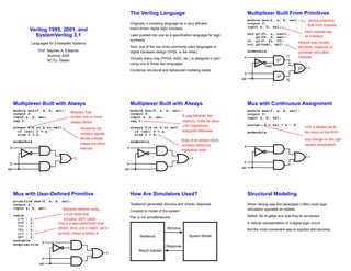
  • 1. Verilog 1995, 2001, and SystemVerilog 3.1 Languages for Embedded Systems Prof. Stephen A. Edwards Summer 2004 NCTU, Taiwan The Verilog Language Originally a modeling language for a very efficient event-driven digital logic simulator Later pushed into use as a specification language for logic synthesis Now, one of the two most commonly-used languages in digital hardware design (VHDL is the other) Virtually every chip (FPGA, ASIC, etc.) is designed in part using one of these two languages Combines structural and behavioral modeling styles Multiplexer Built From Primitives module mux(f, a, b, sel); Verilog programs built from modules output f; input a, b, sel; Each module has an interface and g1(f1, a, nsel), g2(f2, b, sel); or g3(f, f1, f2); not g4(nsel, sel); Module may contain structure: instances of primitives and other modules endmodule g1 g4 g2 g3 a b sel f nsel f1 f2 Multiplexer Built with Always module mux(f, a, b, sel); output f; input a, b, sel; reg f; always Modules may contain one or more always blocks @(a or b or sel) Sensitivity list contains signals whose change makes the block execute if (sel) f = a; else f = b; endmodule a b sel f Multiplexer Built with Always module mux(f, a, b, sel); output f; input a, b, sel; reg f; A reg behaves like memory: holds its value until imperatively assigned otherwise always @(a or b or sel) if (sel) f = a; else f = b; Body of an always block contains traditional imperative code endmodule a b sel f Mux with Continuous Assignment module mux(f, a, b, sel); output f; input a, b, sel; assign LHS is always set to the value on the RHS Any change on the right causes reevaluation f = sel ? a : b; endmodule a b sel f Mux with User-Defined Primitive primitive mux(f, a, b, sel); output f; input a, b, sel; table 1?0 : 1; Behavior defined using a truth table that includes “don’t cares” 0?0 : 0; ?11 : 1; ?01 : 0; 11? : 1; This is a less pessimistic than others: when a & b match, sel is ignored; others produce X 00? : 0; endtable endprimitive a b sel f How Are Simulators Used? Testbench generates stimulus and checks response Coupled to model of the system Pair is run simultaneously Testbench System Model Stimulus Response Result checker Structural Modeling When Verilog was first developed (1984) most logic simulators operated on netlists Netlist: list of gates and how they’re connected A natural representation of a digital logic circuit Not the most convenient way to express test benches
  • 2. Behavioral Modeling A much easier way to write testbenches Also good for more abstract models of circuits • Easier to write • Simulates faster More flexible Provides sequencing Verilog succeeded in part because it allowed both the model and the testbench to be described together How Verilog Is Used Virtually every ASIC is designed using either Verilog or VHDL (a similar language) Behavioral modeling with some structural elements “Synthesis subset” can be translated using Synopsys’ Design Compiler or others into a netlist Design written in Verilog Simulated to death to check functionality Synthesized (netlist generated) Static timing analysis to check timing Two Main Components of Verilog: Behavioral Concurrent, event-triggered processes (behavioral) Initial and Always blocks Imperative code that can perform standard data manipulation tasks (assignment, if-then, case) Processes run until they delay for a period of time or wait for a triggering event Two Main Components of Verilog: Structural Structure (Plumbing) Verilog program build from modules with I/O interfaces Modules may contain instances of other modules Modules contain local signals, etc. Module configuration is static and all run concurrently Two Main Data Types: Nets Nets represent connections between things Do not hold their value Take their value from a driver such as a gate or other module Cannot be assigned in an initial or always block Two Main Data Types: Regs Regs represent data storage Behave exactly like memory in a computer Hold their value until explicitly assigned in an initial or always block Never connected to something Can be used to model latches, flip-flops, etc., but do not correspond exactly Actually shared variables with all their attendant problems Discrete-event Simulation Basic idea: only do work when something changes Centered around an event queue that contains events labeled with the simulated time at which they are to be executed Basic simulation paradigm • Execute every event for the current simulated time • Doing this changes system state and may schedule events in the future • When there are no events left at the current time instance, advance simulated time soonest event in the queue Four-valued Data Verilog’s nets and registers hold four-valued data 0, 1: Obvious Z: Output of an undriven tri-state driver. Models case where nothing is setting a wire’s value X: Models when the simulator can’t decide the value • Initial state of registers • When a wire is being driven to 0 and 1 simultaneously • Output of a gate with Z inputs Four-valued Logic Logical operators work on three-valued logic 0 1 X Z 0 0 0 0 0 Outputs 0 if either input is 0 1 0 1 X X X 0 X X X Outputs X if both inputs are gibberish Z 0 X X X
  • 3. Structural Modeling Nets and Registers Wires and registers can be bits, vectors, and arrays wire a; // Simple wire tri [15:0] dbus; // 16-bit tristate bus tri #(5,4,8) b; // Wire with delay reg [-1:4] vec; // Six-bit register trireg (small) q; // Wire stores a small charge integer imem[0:1023]; // Array of 1024 integers reg [31:0] dcache[0:63]; // A 32-bit memory Modules and Instances Basic structure of a Verilog module: module mymod(out1, out2, Verilog convention lists outputs first in1, in2); output out1; output [3:0] out2; input in1; input [2:0] in2; endmodule Instantiating a Module Instances of module mymod(y, a, b); look like mymod mm1(y1, a1, b1); // Connect-by-position mymod (y2, a1, b1), (y3, a2, b2); // Instance names omitted // Connect-by-name mymod mm2(.a(a2), .b(b2), .y(c2)); Gate-level Primitives Verilog provides the following: and nand logical AND/NAND or nor logical OR/NOR xor xnor logical XOR/XNOR buf not buffer/inverter bufif0 notif0 Tristate with low enable bifif1 notif1 Tristate with high enable Delays on Primitive Instances Instances of primitives may include delays buf b1(a, b); // Zero delay buf #3 b2(c, d); // Delay of 3 buf #(4,5) b3(e, f); // Rise=4, fall=5 buf #(3:4:5) b4(g, h); // Min-typ-max Switch-level Primitives Verilog also provides mechanisms for modeling CMOS transistors that behave like switches A more detailed modeling scheme that can catch some additional electrical problems when transistors are used in this way Now, little-used because circuits generally aren’t built this way More seriously, model is not detailed enough to catch many of the problems These circuits are usually simulated using SPICE-like simulators based on nonlinear differential equation solvers User-Defined Primitives Way to define gates and sequential elements using a truth table Often simulate faster than using expressions, collections of primitive gates, etc. Gives more control over behavior with X inputs Most often used for specifying custom gate libraries A Carry Primitive primitive carry(out, a, b, c); output out; Always has exactly one output input a, b, c; table 00? : 0; 0?0 : 0; ?00 : 0; Truth table may include don’t-care (?) entries 11? : 1; 1?1 : 1; ?11 : 1; endtable endprimitive
  • 4. A Sequential Primitive Primitive dff( q, clk, data); output q; reg q; input clk, data; table // clk data q new-q (01) 0 : ? : 0; // Latch a 0 (01) 1 : ? : 1; // Latch a 1 (0x) 1 : 1 : 1; // Hold when d and q both 1 (0x) 0 : 0 : 0; // Hold when d and q both 0 (?0) ? : ? : -; // Hold when clk falls ? (??) : ? : -; // Hold when clk stable endtable endprimitive Continuous Assignment Another way to describe combinational function Convenient for logical or datapath specifications wire [8:0] sum; Define bus widths wire [7:0] a, b; wire carryin; assign sum = a + b + carryin; Continuous assignment: permanently sets the value of sum to be a+b+carryin. Recomputed when a, b, or carryin changes Behavioral Modeling Initial and Always Blocks initial begin // imperative statements end Runs when simulation starts Terminates when control reaches the end Good for providing stimulus always begin // imperative statements end Runs when simulation starts Restarts when control reaches the end Good for modeling or specifying hardware Initial and Always Run until they encounter a delay initial begin #10 a = 1; b = 0; #10 a = 0; b = 1; end or a wait for an event always @(posedge clk) q = d; always begin wait(i); a = 0; wait( i); a = 1; end Procedural Assignment Inside an initial or always block: sum = a + b + cin; Just like in C: RHS evaluated and assigned to LHS before next statement executes RHS may contain wires and/or regs LHS must be a reg (only primitives or continuous assignment may set wire values) Imperative Statements if (select == 1) y = a; else y = b; case (op) 2’b00: y = a + b; 2’b01: y = a - b; 2’b10: y = a ˆ b; default: y = ’hxxxx; endcase For Loops Example generates an increasing sequence of values on an output reg [3:0] i, output; for ( i = 0 ; i <= 15 ; i = i + 1 ) begin output = i; #10; end While Loops A increasing sequence of values on an output reg [3:0] i, output; i = 0; while (i <= 15) begin output = i; #10 i = i + 1; end
  • 5. Modeling A Flip-Flop With Always Very basic: an edge-sensitive flip-flop reg q; always @(posedge clk) q = d; q = d assignment runs when clock rises: exactly the behavior you expect Blocking vs. Nonblocking Verilog has two types of procedural assignment Fundamental problem: • In a synchronous system, all flip-flops sample simultaneously • In Verilog, always @(posedge clk) blocks run in some undefined sequence A Flawed Shift Register This does not work as you would expect: reg d1, d2, d3, d4; always @(posedge clk) d2 = d1; always @(posedge clk) d3 = d2; always @(posedge clk) d4 = d3; These run in some order, but you don’t know which Non-blocking Assignments This version does work: reg d1, d2, d3, d4; always @(posedge clk) d2 <= d1; Nonblocking rule: RHS evaluated when assignment runs always @(posedge clk) d3 <= d2; always @(posedge clk) d4 LHS updated only after all events for the current instant have run <= d3; Nonblocking Can Behave Oddly A sequence of nonblocking assignments don’t communicate a = 1; b = a; c = b; Blocking assignment: a = b = c = 1 a <= 1; b <= a; c <= b; Nonblocking assignment: a = 1 b = old value of a c = old value of b Nonblocking Looks Like Latches RHS of nonblocking taken from latches RHS of blocking taken from wires a = 1; b = a; c = b; “1 c a b ” a <= 1; b <= a; c <= b; “ 1 c a b ” Building Behavioral Models Modeling FSMs Behaviorally There are many ways to do it: • Define the next-state logic combinationally and define the state-holding latches explicitly • Define the behavior in a single always @(posedge clk) block • Variations on these themes FSM with Combinational Logic module FSM(o, a, b, reset); output o; reg o; Output o is declared a reg because it is assigned procedurally, not because it holds state input a, b, reset; reg [1:0] state, nextState; always @(a or b or state) case (state) 2’b00: begin o = a & b; nextState = a ? 2’b00 : 2’b01; end 2’b01: begin o = 0; nextState = 2’b10; end endcase always @(posedge clk or reset) if (reset) state <= 2’b00; else state <= nextState; endmodule
  • 6. FSM with Combinational Logic module FSM(o, a, b, reset); output o; reg o; input a, b, reset; reg [1:0] state, nextState; always @(a or b or state) Combinational block must be sensitive to any change on any of its inputs (Implies state-holding elements otherwise) case (state) 2’b00: begin o = a & b; nextState = a ? 2’b00 : 2’b01; end 2’b01: begin o = 0; nextState = 2’b10; end endcase always @(posedge clk or reset) Latch implied by sensitivity to the clock or reset only if (reset) state <= 2’b00; else state <= nextState; endmodule FSM from a Single Always Block module FSM(o, a, b); output o; reg o; input a, b; reg [1:0] state; always @(posedge clk or reset) Expresses Moore machine behavior: Outputs are latched. Inputs only sampled at clock edges if (reset) state <= 2’b00; else case (state) 2’b00: begin state <= a ? 2’b00 : 2’b01; o <= a & b; end 2’b01: begin state <= 2’b10; o <= 0; Nonblocking assignments used throughout to ensure coherency. RHS refers to values calculated in previous clock cycle end endcase Writing Testbenches module test; reg a, b, sel; Inputs to device under test mux m(y, a, b, sel); Device under test initial begin $monitor $monitor is a built-in even-driven “printf” ($time,,"a=%b b=%b sel=%b y=%b", a, b, sel, y); a = 0; b= 0; sel = 0; #10 a = 1; #10 sel = 1; Stimulus generated by sequence of assignments and delays #10 b = 1; end Simulating Verilog Simulation Behavior Scheduled using an event queue Non-preemptive, no priorities A process must explicitly request a context switch Events at a particular time unordered Scheduler runs each event at the current time, possibly scheduling more as a result Two Types of Events Evaluation events compute functions of inputs Update events change outputs Split necessary for delays, nonblocking assignments, etc. Update event writes new value of a and schedules any evaluation events that are sensitive to a change on a a <= b + c Evaluation event reads values of b and c, adds them, and schedules an update event Simulation Behavior Concurrent processes (initial, always) run until they stop at one of the following • #42 Schedule process to resume 42 time units from now • wait(cf & of) Resume when expression “cf & of” becomes true • @(a or b or y) Resume when a, b, or y changes • @(posedge clk) Resume when clk changes from 0 to 1 Simulation Behavior Infinite loops are possible and the simulator does not check for them This runs forever: no context switch allowed, so ready can never change while (˜ready) count = count + 1; Instead, use wait(ready); Simulation Behavior Race conditions abound in Verilog These can execute in either order: final value of a undefined: always @(posedge clk) a = 0; always @(posedge clk) a = 1;
  • 7. Simulation Behavior Semantics of the language closely tied to simulator implementation Context switching behavior convenient for simulation, not always best way to model Undefined execution order convenient for implementing event queue Compiled-Code Discrete-Event Sim. Most modern simulators use this approach Verilog program compiled into C Each concurrent process (e.g., continuous assignment, always block) becomes one or more C functions Initial and always blocks split into multiple functions, one per segment of code between a delay, a wait, or event control (@) Central, dynamic event queue invokes these functions and advances simulation time Verilog and Logic Synthesis Logic Synthesis Verilog is used in two ways Model for discrete-event simulation Specification for a logic synthesis system Logic synthesis converts a subset of the Verilog language into an efficient netlist One of the major breakthroughs in designing logic chips in the last 20 years Most chips are designed using at least some logic synthesis Logic Synthesis Tools Mostly commercial tools • Very difficult, complicated programs to write well • Limited market • Commercial products in $10k – $100k price range Major vendors • Synopsys Design Compiler, FPGA Express • Cadence BuildGates • Synplicity (FPGAs) • Exemplar (FPGAs) Academic tools • SIS (UC Berkeley) Logic Synthesis Takes place in two stages: 1. Translation of Verilog (or VHDL) source to a netlist Register inference performed here 2. Optimization of the resulting netlist to improve speed and area Most critical part of the process Algorithms very complicated and beyond the scope of this class Logic Optimization Netlist optimization the critical enabling technology Takes a slow or large netlist and transforms it into one that implements the same function more cheaply Typical operations: • Constant propagation • Common subexpression elimination • Function factoring Time-consuming operation. Can take hours for large chips Translating Verilog into Gates Parts of the language easy to translate Structural descriptions with primitives is already a netlist Continuous assignment expressions turn into little datapaths Behavioral statements the bigger challenge What Can Be Translated Every structural definition Behavioral blocks • Depends on sensitivity list • Only when they have reasonable interpretation as combinational logic, edge, or level-sensitive latches • Blocks sensitive to both edges of the clock, changes on unrelated signals, changing sensitivity lists, etc. cannot be synthesized User-defined primitives • Primitives defined with truth tables • Some sequential UDPs can’t be translated (not latches or flip-flops)
  • 8. What Is Not Translated Initial blocks • Used to set up initial state or describe finite testbench stimuli • Don’t have obvious hardware component Delays • May be in the Verilog source, but are simply ignored A variety of other obscure language features • In general, things heavily dependent on discrete-event simulation semantics • Certain “disable” statements • Pure events Register Inference The main trick A reg is not always a latch or flip-flop Rule: Combinational if outputs always depend exclusively on sensitivity list Sequential if outputs may also depend on previous values Register Inference Combinational: reg y; always @(a or b or sel) Sensitive to changes on all the variable it reads if (sel) y = a; else y = b; y is always assigned Sequential: reg q; always @(d or clk) if (clk) q = d; q only assigned when clk is 1 Register Inference A common mistake is not completely specifying a case statement This implies a latch: always @(a or b) case ({a, b}) 2’b00 : f = 0; 2’b01 : f = 1; 2’b10 : f = 1; endcase f is not assigned when {a,b}= 2’b11 Register Inference The solution is to always have a default case always @(a or b) case ({a, b}) 2’b00 : f = 0; 2’b01 : f = 1; 2’b10 : f = 1; default : f = 0; f is always assigned endcase Inferring Latches with Reset Latches and Flip-flops often have reset inputs Can be synchronous or asynchronous Asynchronous positive reset: always @(posedge clk or posedge reset) if (reset) q <= 0; else q <= d; Simulation-synthesis Mismatches Many possible sources of conflict • Synthesis ignores delays (e.g., #10), but simulation behavior can be affected by them • Simulator models X explicitly, synthesis does not • Behaviors resulting from shared-variable-like behavior of regs is not synthesized: always @(posedge clk) a = 1; New value of a may be seen by other @(posedge clk) statements in simulation, never in synthesis Summary of Verilog 1995 Systems described hierarchically • Modules with interfaces • Modules contain instances of primitives, other modules • Modules contain initial and always blocks Based on discrete-event simulation semantics • Concurrent processes with sensitivity lists • Scheduler runs parts of these processes in response to changes Modeling Tools Switch-level primitives: CMOS transistors as switches that move around charge Gate-level primitives: Boolean logic gates User-defined primitives: Gates and sequential elements defined with truth tables Continuous assignment: Modeling combinational logic with expressions Initial and always blocks: Procedural modeling of behavior
  • 9. Language Features Nets (wires) for modeling interconnection • Non state-holding • Values set continuously Regs for behavioral modeling • Behave exactly like memory for imperative modeling • Do not always correspond to memory elements in synthesized netlist Blocking vs. nonblocking assignment • Blocking behaves like normal “C-like” assignment • Nonblocking delays update, modeling synchronous behavior Language Uses Event-driven simulation • Event queue containing things to do at particular simulated times • Evaluate and update events • Compiled-code event-driven simulation for speed Logic synthesis • Translating Verilog (structural and behavioral) into netlists • Register inference: whether output is always updated • Logic optimization for cleaning up the result Little-used Language Features Switch-level modeling • Much slower than gate or behavioral-level models • Insufficient detail for modeling most electrical problems • Delicate electrical problems simulated with a SPICE-like differential equation simulator Little-used Language Features Delays • Simulating circuits with delays does not improve confidence enough • Hard to get timing models accurate enough • Never sure you have simulated the worst case • Static timing analysis has taken its place Compared to VHDL Verilog and VHDL are comparable languages VHDL has a slightly wider scope • System-level modeling • Exposes even more discrete-event machinery VHDL is better-behaved: Fewer sources of nondeterminism (e.g., no shared variables) VHDL is harder to simulate quickly VHDL has fewer built-in facilities for hardware modeling VHDL is a much more verbose language: Most examples don’t fit on slides In Conclusion Verilog is a deeply flawed language • Nondeterministic • Often weird behavior due to discrete-event semantics • Vaguely defined synthesis subset • Many possible sources of simulation/synthesis mismatch In Conclusion Verilog is widely used because it solves a problem • Good simulation speed that continues to improve • Designers use a well-behaved subset of the language • Makes a reasonable specification language for logic synthesis • Logic synthesis one of the great design automation success stories Verilog 2001 Verilog 2001 Revised version of the Verilog language IEEE Standard 1364-2001 Minor changes to the language: ANSI C style ports standard file I/O (* attributes *) multi dimensional arrays generate $value$plusargs configurations signed types localparam ‘ifndef ‘elsif ‘line memory part selects automatic constant functions @* variable part select ** (power operator)
  • 10. Implicit event lists Common mistake: forgetting a variable in combinational sensitivity list always @(a or b or c Forgot to include d ) f = a & b | c & d; Does not simulate like hardware behaves. Verilog 2001’s implicit sensitivity list: always @* f = a & b | c & d; Makes process sensitive to all variables on right-hand side of assignments. Generate Hardware structures often very regular. Want to create them algorithmically. Verilog’s generate: very clever macro expansion. module gray2bin1 (bin, gray); parameter SIZE = 8; output [SIZE-1:0] bin; input [SIZE-1:0] gray; genvar i; // Compile-time only generate for (i=0; i<SIZE; i=i+1) begin:bit assign bin[i] = ˆgray[SIZE-1:i]; end endgenerate endmodule Attributes Logic synthesis has relied on hints in comments: always @(posedge clk) begin case (instr[6:5]) // synopsys full_case parallel_case 0 : mask <= 8’h01; 1 : mask <= 8’h02; 2 : mask <= 8’h04; 3 : mask <= 8’h08; endcase end full_case means one case will always be true, parallel_case means at most one will be true. Can greatly simplify the generated logic, but simulation/synthesis mismatch if assertion is not true. Attributes Such attributes now a first-class part of the language. Simulator understands and checks validity. always @(posedge clk) begin (* full_case, parallel_case=1 *) case (instr[6:5]) 0 : mask <= 8’h01; 1 : mask <= 8’h02; 2 : mask <= 8’h04; 3 : mask <= 8’h08; endcase end ANSI C-style ports Verilog 1995 ports could require three declarations: module foo(myport1, myport2); output myport1; reg [7:0] myport1; input [3:0] myport2; ... endmodule Verilog 2001 reduces this to one: module foo(output reg [7:0] myport1, input [3:0] myport2); ... endmodule Configurations file lib.map library gateLib ./*.vg; library rtlLib *.v; // specify rtl adder for top.a1 // gate-level adder for top.a2 config cfg1; design rtlLib.top; default liblist rtlLib; instance top.a2 liblist gateLib; endconfig A way to select among different implementations using the same top-level modules. file adder.v module adder(...); // RTL adder // implementation ... endmodule file top.v module top(); adder a1(...); adder a2(...); endmodule file adder.vg module adder(...); // gate-level adder ... endmodule SystemVerilog SystemVerilog Much bigger change to the language. Verification Features assertions biased random variables test program blocks process control mailboxes semaphores clocking domains direct C function calls C++-like features classes dynamic arrays inheritance associative arrays strings references More System Verilog Features C-like features int shortint longint byte shortreal void alias enum struct union const typedef break continue return do while casting globals ++ -- += -= *= /= >>= <<= >>>= <<<= &= |= ˆ= %= Modeling Features interfaces dynamic processes nested hierarchy 2-state modeling unrestricted ports packed arrays implicit port connections array assignments enhanced literals enhanced event control time values & units unique/priority case/if logic-specific processes root name space access
  • 11. C-like Features New Types type values width new reg { 0, 1, X, Z } 1+ logic { 0, 1, X, Z } 1+ ✓ integer { 0, 1, X, Z } 32 bit { 0, 1 } 1+ ✓ byte { 0, 1 } 8 ✓ shortint { 0, 1 } 16 ✓ int { 0, 1 } 32 ✓ longint { 0, 1 } 64 ✓ reg & logic now the same: both permit either continuous or procedural assignment, but not both. Other new types for two-valued functional simulation. ‘ifdef and typedef Can define aliases for existing types. Useful, e.g., for switching between four- and two-valued simulation: ‘ifdef TWOSTATE typedef bit bit_t; ‘else typedef logic bit_t; ‘endif module dff ( output bit_t q, input bit_t d, clk, rst); always @(posedge clk) if (rst) q <= 0; else q <= d; endmodule Structs and Unions SystemVerilog provides C-like structs and unions in both packed and unpacked forms. typedef struct { logic PARITY; logic[3:0] ADDR; logic[3:0] DEST; } pkt_t; pkt_t mypkt; mkpkt.ADDR = 12; Packed vs. Unpacked Structs are unpacked by default. The alignment of their fields is implementation-dependent for efficiency, e.g., chosen by the C compiler. typedef struct { logic PARITY; logic[3:0] ADDR; logic[3:0] DEST; } pkt_t; 31 3 1 0 PARITY ADDR DATA Packed vs. Unpacked Marking them packed removes padding: useful in unions. typedef struct packed { logic PARITY; logic[3:0] ADDR; logic[3:0] DEST; } pkt_t; 8 5 4 1 0 DEST ADDR PARITY Packed Structs and Unions typedef struct packed { logic [15:0] source_port; logic [15:0] dest_port; logic [31:0] sequence; } tcp_t; typedef struct packed { logic [15:0] source_port; logic [15:0] dest_port; logic [15:0] length; logic [15:0] checksum; } udp_t; typedef union packed { tcp_t tcp_h; udp_t udp_h; bit [63:0] bits; bit [7:0][7:0] bytes; } ip_t; ip_t ip_h; logic parity; // all are equivalent ip_h.upd_h.length = 5; ip_h.bits[31:16] = 5; ip_h.bytes[3:2] = 5; tcp_t source_port dest_port sequence udp_t source_port dest_port length checksum Operator Overloading SystemVerilog provides operator overloading facilities like those in C++ through the bind keyword. typedef struct { bit sign; bit [3:0] exponent; bit [10:0] mantissa; }float; bind + function float faddfr(float, real); bind + function float faddff(float, float); float A, B, C, D; assign A = B + C; // means A = faddff(B, C); assign D = A + 1.0; // means A = faddfr(A, 1.0); Classes SystemVerilog provides C++-like classes with automatic garbage collection. class Packet; bit [3:0] cmd; int status; header_t header; function int get_status(); return status; endfunction extern task set_cmd(input bit [3:0] a); endclass task Packet::set_cmd(input bit [3:0] a); cmd = a; endtask initial begin Packet myPkt = new; // Create a new packet end
  • 12. Inheritance As in C++, classes can inherit from other classes: class ErrPkt extends Packet; bit [3:0] err; // New function function bit [3:0] show_err; return err; endfunction // Overrides Packet::set cmd task set_cmd(input bit [3:0] a); cmd = a + 1; endtask endclass Packages package ComplexPkg; typedef struct { float i, r; } Complex; function Complex add(Complex a, b); add.r = a.r + b.r; add.i = a.i + b.i; endfunction function Complex mul(Complex a, b); mul.r = (a.r * b.r) + (a.i * b.i); mul.i = (a.r * b.i) + (a.i * b.r); endfunction endpackage : ComplexPkg module foo (input bit clk); import ComplexPkg::*; Complex a,b; always @(posedge clk) c = add(a,b); endmodule Hardware Modeling Features always comb, latch, and ff In RTL design, a Verilog always block models combinational logic, sequential logic driving flip-flops, or sequential logic driving latches, never more than one. SystemVerilog’s always comb, always ff, and always latch keywords make the designer’s intent clear to the compiler so it can issue error messages. always comb, latch, and ff // Probably intended combinational, but c becomes latch always @(a or b) if (b) c = a; // Error: “missing else branch: c is not assigned” always_comb if (b) c = a; // A correct level-sensitive latch always_latch if (clk) if (en) q <= d; // Error: “q always assigned: it is not a latch” always_latch q <= d always comb, latch, and ff Compiler verifies coding style. // Correct edge-sensitive FF with asynchronous reset always_ff @(posedge clk, negedge rst_n) if (!rst_n) q <= 0; else q <= d; // Error: sensitivity not on edges always_ff @(clk, rst_n) if (!rst_n) q <= 0; else q <= d; // Error: combinational logic loop always_latch if (en) q <= d; else q <= q; // Error Unique/Priority Verilog 1995 had no provision for checking uniqueness of conditions: synthesis tools placed pragmas in comments. Verilog 2001 added attributes for such conditions as first-class entities. SystemVerilog introduces new keywords implying unique and complete conditions. Cases must be Condition must be complete unique priority ✓ unique ✓ ✓ Priority Examples // error if none of irq0–irq2 is true priority case (1’b1) irq0: irq = 3’b1 << 0; irq1: irq = 3’b1 << 1; irq2: irq = 3’b1 << 2; endcase // error if none of irq0–irq2 is true priority if (irq0) irq = 3’b1; else if (irq1) irq = 3’b2; else if (irq2) irq = 3’b4; // Default or else ignores priority // This never raises an error: priority if (irq0) irq = 3’b1; else irq = 3’b0; // Nor does this: priority case (1’b1) irq0: irq = 3’b1 << 0; default: irq = 0; endcase Unique Examples // Error if not exactly one of irq0–irq2 is true unique case (1’b1) irq0: irq = 3’b1 << 0; irq1: irq = 3’b1 << 1; irq2: irq = 3’b1 << 2; endcase // Error if not exactly one of irq0–irq2 is true unique if (irq0) irq = 3’b1; else if (irq1) irq = 3’b2; else if (irq2) irq = 3’b4; // Error if both irq0 and irq1 are true unique if (irq0) irq = 3’b1; else if (irq1) irq = 3’b2; else irq = 3’b0; // Error if both irq0 and irq1 are true: unique case (1’b1) irq0: irq = 3’b1 << 0; irq1: irq = 3’b1 << 1; default: irq = 0; endcase
  • 13. Implicitly-named ports Hierarchy in Verilog usually for separating namespaces. Net and port names typically common across modules. Verbose in Verilog 1995: module top; wire [3:0] a; wire [7:0] b; wire [15:0] c; foo foo1(a, b, c); bar bar1(a, b, c); endmodule module foo(a, b, c); input [3:0] a; input [7:0] b; input [15:0] c; endmodule module bar(a, b, c); output a; output b; output c; reg [3:0] a; reg [7:0] b; reg [15:0] c; endmodule Implicity-named Ports Implicit ports plus ANSI-style declarations makes this cleaner, especially for modules with many ports. module top; wire [3:0] a; wire [7:0] b; wire [15:0] c; foo foo1(.*); bar bar1(.*); endmodule module foo( input [3:0] a, input [7:0] b, input [15:0] c); endmodule module bar( output reg [3:0] a, output reg [7:0] b, output reg [15:0] c); endmodule Implicity-named Ports Port renaming also supported. Allows specific ports to be overridden or renamed as necessary. module top; wire [3:0] a; wire [7:0] b; wire [15:0] c; foo foo1(.*); bar bar1(.*, .other(c)); endmodule module foo( input [3:0] a, input [7:0] b, input [15:0] c); endmodule module bar( output reg [3:0] a, output reg [7:0] b, output reg [15:0] other); endmodule Interfaces For communication among modules. Like a collection of shared variables. interface simple_bus; logic req, gnt; logic [7:0] addr, data; logic [1:0] mode; logic start, rdy; endinterface : simple_bus module top; logic clk = 0; simple_bus mybus; memory mem(mybus, clk); cpu cpu(.b(mybus), .clk(clk)); endmodule module memory( simple_bus a, input bit clk); always @(posedge clk) a.gnt <= a.req & avail; ... endmodule module cpu(simple_bus b, input bit clk); ... endmodule Interfaces with implicit ports Even more simple. Use the same names and let the compiler do the rest. interface simple_bus; logic req, gnt; logic [7:0] addr, data; logic [1:0] mode; logic start, rdy; endinterface : simple_bus module top; logic clk = 0; simple_bus bus; memory mem(.*); cpu cpu(.*); endmodule module memory( simple_bus bus, input bit clk); always @(posedge clk) bus.gnt <= bus.req & av; ... endmodule module cpu(simple_bus bus, input bit clk); ... endmodule Generic bundles You can leave the exact type of an interface unspecified to allow different implementations. Must connect explicitly. interface simple_bus; logic req, gnt; logic [7:0] addr, data; logic [1:0] mode; logic start, rdy; endinterface : simple_bus module top; logic clk = 0; simple_bus bus; memory mem(.*, .bus(bus)); cpu cpu(.*, .bus(bus)); endmodule module memory( interface bus, input bit clk); always @(posedge clk) bus.gnt <= bus.req & av; ... endmodule module cpu(interface bus, input bit clk); ... endmodule Ports on interfaces Interfaces are groups of shared variables. Ports on interfaces can bring connections in or out. interface bus( input bit clk, output bit bus_error); logic req, gnt; logic [7:0] addr, data; logic [1:0] mode; logic start, rdy; endinterface : bus module top; logic clk = 0, bus_error; bus b(clk, bus_error); memory mem(.*); cpu cpu(.*); endmodule module memory(bus b); always @(posedge b.clk) b.gnt <= b.req & av; ... endmodule module cpu(bus b); always @(posedge b.clk) b.bus_error <= cpu_error; ... endmodule Modports in interfaces A way to constrain signal directions in interfaces. interface bus( input bit clk); logic req, gnt, rdy; logic [7:0] addr, data; modport slave( input req, addr, clk, output gnt, rdy, inout data); modport master( output req, addr, input gnt, rdy, clk, inout data) endinterface : bus module top; logic clk = 0; bus b(clk); memory mem(.*); cpu cpu(.*); endmodule module memory(bus.slave b); always @(posedge bus.clk) b.gnt <= b.req & av; ... endmodule module cpu(bus.master b); ... endmodule Tasks and Functions in Interfaces interface bus; logic start; task slaveRead( input logic[7:0] addr); ... endtask: slaveRead task masterRead( input logic[7:0] addr); ... endtask: masterRead modport slave( import task slaveRead( input logic[7:0] addr); ); endinterface: bus module memory(interface b); logic[7:0] addr; always @(posedge b.clk) b.slaveRead(addr); endmodule module omnip(interface b); always @(posedge b.clk) b.masterRead(addr); always @(posedge b.clk) b.slaveRead(addr); endmodule module top; bus b; // can invoke slaveRead only memory m(b.slave); // can use slaveRead, masterRead omnip o(b); endmodule
  • 14. Dynamically-sized Arrays Truly software-like behavior. module dynamic_array; bit[3:0] myarray[]; // Creates null reference initial begin myarray = new[4]; // Allocate four 4-bit words // Double the size of the array, preserving its contents myarray = new[myarray.size() * 2](myarray); end endmodule Associative Arrays Very abstract notion. Like maps in C++, hashtables in Java, or associative arrays in Perl, Python, Awk. module associative_array; typedef struct packed { int a; logic [7:0] b; } mykey_t; int myarray[mykey_t]; // new, empty associative array initial begin mykey_t key1 = {-3, 8’xFE }; // structure literal myarray[key1] = 10; if (myarray.exists(key1)) myarray[key1] = -5; myarray.delete(key1); end endmodule Queues Often used to communicate between processes. module queues; int q[$] = { 2, 4, 8 }; // initial contents int sq[$:15]; // maximum size is 16 initial begin int e = q[0]; // first item: 2 e = q[$]; // last item: 8 q = { q, 6 }; // append: now 2, 4, 8, 6 q = { e, q }; // insert: now 8, 2, 4, 8, 6 q = q[1:$]; // remove: now 2, 4, 8, 6 q = q[1:$-1]; // delete first, last: now 4, 8 end endmodule Process Management: join Fork starts processes; join terminates when all blocks terminate. fork begin $display("0ns have elapsedn"); # 20ns; // delay end begin # 20ns; $display("20ns have elapsedn"); # 5ns; end join # 5ns; $display("30ns have elapsedn"); Process Management: join any Fork starts processes; join any terminates when any of its blocks terminate. fork begin $display("0ns have elapsedn"); # 20ns; // delay end begin # 20ns; $display("20ns have elapsedn"); # 5ns; end join_any # 5ns; $display("25ns have elapsedn"); Process Management: join none Fork starts processes; join none terminates immediately, leaving its blocks running. fork begin $display("0ns have elapsedn"); # 20ns; // delay end begin # 20ns; $display("20ns have elapsedn"); # 5ns; end join_none # 5ns; $display("5ns have elapsedn"); Process Management: wait fork wait fork waits for all children to terminate. task wait_fork_demo; fork task1(); // start task1 and task2 concurrently task2(); join_any // terminates when either task1 or task2 does fork task3(); // start task3 and task4 concurrently task4(); join_none; // task3 and task4 and either task1 or task2 running wait fork; // wait for all to complete endtask Process Management: disable fork disable fork terminates all its children. task wait_for_first( output int adr ); fork wait_device( 1, adr); // user-defined task that waits wait_device( 7, adr); // all three started concurrently wait_device(13, adr); join_any // terminate when one has arrived disable fork; // terminate other two Process control task run_n_jobs_and_terminate_after_first(int N); process job[1:N]; // The processes we spawn for (int j = 1 ; j <= N ; j++) fork automatic int k = j; // for each job, k is its number begin job[j] = process::self(); // record who I am ... // the job itself end join_none // spawn next job immediately for (int j = 1 ; j <= N ; j++) wait( job[j] != null ); // wait for jobs to start job[1].await(); // wait for first job to finish for (int k = 1 ; k <= N ; k++ ) begin if (job[k].status != process::FINISHED) // if not finished, job[k].kill(); // kill it end endtask
  • 15. Semaphores Mutually-exclusive keys in a bucket. get blocks if not enough keys are available. semaphore we_are_there = new; // initialize with no keys task drive; fork begin # 100ns; // delay 100ns we_are_there.put(1); // put a single key in the semaphore end begin $display("Are we there yet?n"); we_are_there.get(1); // wait for a key $display("We made itn"); end join endtask Semaphores and events event ask, answered; semaphore answer = new; int winner; // only valid after answer task gameshow; fork begin // the host -> ask; // Start the two contestants answer.put(1); // let them compete @answered; $display("%d was firstn", winner); end begin // contestant one @ask; // wait for the question think_about_answer(); answer.get(1); // try to answer first winner = 1; -> answered; // signal our success end begin // contestant two @ask; think_about_answer(); answer.get(1); winner = 2; -> answered; end join // Does this behave properly? endtask Mailboxes Possibly bounded semaphore-like queues. mailbox #(string) mybox = new(2); // capacity set to two task mailbox_demo; fork begin mybox.put("first letter"); $display("sent firstn"); mybox.put("second letter"); $display("sent secondn"); mybox.put("third letter"); $display("sent thirdn"); end begin $display("got %sn", mybox.get); $display("got %sn", mybox.get); $display("got %sn", mybox.get); end join endtask Prints sent first sent second got first letter got second letter sent third got third letter Verification Features Constrained Random Variables Manually creating test cases tedious and difficult, yet appears necessary for functional verification. Current best practice: Constrained random tests. SystemVerilog has features for creating such tests. Constrained Random Variables class Bus; rand bit[15:0] addr; rand bit[31:0] data; constraint world_align { addr[1:0] = 2’b0; } endclass Bus bus = new; repeat (50) begin if (bus.randomize() == 1) $display("addr = %16h data = %hn", bus.addr, bus.data); else $display("overconstrained: no satisfying values existn"); end Adding constraints class Bus; rand bit[15:0] addr; rand bit[31:0] data; constraint world_align { addr[1:0] = 2’b0; } endclass Bus bus = new; repeat (50) begin if (bus.randomize() with { addr[31] == 0 } == 1) $display("addr = %16h data = %hn", bus.addr, bus.data); else $display("overconstrained: no satisfying values existn"); end Layering constraints Constraints inherited, can be added in derived classes. class Bus; rand bit[15:0] addr; rand bit[31:0] data; constraint world_align { addr[1:0] = 2’b0; } endclass typdef enum { low, mid, high } AddrType; class MyBus extends Bus; rand AddrType atype; // Additional random variable // Additional constraint on address: still word-aligned constraint addr_range { (atype == low ) -> addr inside { [0:15] }; (atype == mid ) -> addr inside { [16:127] }; (atype == high) -> addr inside { [128:255] }; } endclass Using Constraints Very powerful constraint solving algorithm. task exercise_bus; int res; // Restrict to low addresses res = bus.randomize() with { atype == low; }; // Restrict to particular address range res = bus.randomize() with { 10 <= addr && addr <= 20 }; // Restrict data to powers of two res = bus.randomize() with { data & (data - 1) == 0 }; // Disable word alignment bus.word_align.constraint_mode(0); res = bus.randomize with { addr[0] || addr[1] }; // Re-enable word alignment bus.word_align.constraint_mode(1); endtask
  • 16. Other types of constraints // Set membership constraints rand integer x, y, z; constraint c1 { x inside {3, 5, [9:15], [y:2*y], z}; } integer fives[0:3] = { 5, 10, 15, 20 }; rand integer v; constraint c2 { v inside fives; } // Distribution constraints rand integer w; // make w 100 1/8 of time, 200 2/8, 300 5/8 constraint c3 { w dist {100 := 1, 200 := 2, 300 := 5 }; } // Implication constraints bit [3:0] a, b; // force b to 1 when a is 0 constraint c4 { (a == 0) -> (b == 1); } Many, many more features Variables that step through random permutations (randc) If-then-else constraints Algorithmic constraints over array entries (foreach) Constraints among multiple objects Variable ordering constraints (solve..before) Static constraints controlled by one constraint mode() call Functions in constraints Guarded constraints pre- and post-randomize functions Random variable disabling Explicit randomization of arbitrary variables Random sequence generation from a grammar Coverage Checks Once we have generated our tests, how good are they? Current best practice: monitoring and improving coverage Coverage: how many cases, statements, values, or combinations have the test cases exercised? Covergroup Defines something whose coverage is to be checked. Creates bins and tracks whether values ever appeared. // color: a three-valued variable whose coverage is to be checked enum { red, green, blue } color; covergroup g1 @(posedge clk); // Sample at posedge clk c: coverpoint color; endgroup g1 g1_inst = new; // Create the coverage object At the end of simulation, reports whether color took all three of its values. Cross Coverage May want to monitor combinations of variables. enum { red, green, blue } color; bit [3:0] pixel_adr, pixel_offset; covergroup g2 @(posedge clk); Hue: coverpoint pixel_hue; Offset: coverpoint pixel_offset; // Consider (color, pixel adr) pairs, e.g., // (red, 3’b000), (red, 3’b001), ..., (blue, 3’b111) AxC: cross color, pixel_adr; // Consider (color, pixel hue, pixel offset) triplets // Creates 3 * 16 * 16 = 768 bins all: cross color, Hue, Offset; endgroup g2 g2_inst = new; // Create a watcher Covergroup in classes Individual coverage of each object of a class. class xyz; bit [3:0] x; int y; bit z; covergroup cov1 @z; // At every change of z, coverpoint x; // sample x coverpoint y; // and sample y. endgroup function new(); cov1 = new; // Create a watcher; variable cov1 implicit endfunction endclass Predicated coverage May want to selectively disable coverage: covergroup g4 @(posedge clk); // check s0 only if reset is true coverpoint s0 iff(!reset); endgroup User-defined bins May only want to track certain values of a variable. bit [9:0] a; // Takes values 0–1023 covergroup cg @(posedge clk); coverpoint a { // place values 0–63 and 65 in bin a bins a = { [0:63], 65 }; // create 65 bins, one for 127, 128, ..., 191 bins b[] = { [127:150], [148:191] }; // create three bins: 200, 201, and 202 bins c[] = { 200, 201, 202 }; // place values 1000–1023 in bin d bins d = {[1000:$] }; // place all other values (e.g., 64, 66, .., 126, 192, ...) in their own bin bins others[] = default; } endgroup Covering Transitions May want to check transitions, not just a variable’s values. bit [3:0] a; covergroup cg @(posedge clk); coverpoint a { // Place any of the sequences 4→5→6, 7→11, 8→11, 9→11, 10→11, // 7→12, 8→12, 9→12, and 10→12 into bin sa. bins sa = (4 => 5 => 6), ([7:9],10 => 11,12); // Create separate bins for 4→5→6, 7→10, 8→10, and 9→10 bins sb[] = (4 => 5 => 6), ([7:9] => 10); // Look for the sequence 3→3→3→3 bins sc = 3 [* 4]; // Look for any of the sequences 5→5, 5→5→5, or 5→5→5→5 bins sd = 5 [* 2:4]; // Look for any sequence of the form 6→· · ·→6→· · ·→6 // where “· · ·” represents any sequence that excludes 6 bins se = 6 [-> 3]; } endgroup
  • 17. Assertions We have generated our tests, they do a reasonable job covering the design, but how do we find problems? Current best practice: Add assertions to the design that check for unwanted conditions. Currently, the most effective way to reduce debugging time: bugs found more quickly, and easier to remedy. Long used in software, growing use in hardware. Main challenge in hardware: asserting temporal behavior. SystemVerilog has constructs specifically for checking sequences of things. Immediate Assertions Simplest assertions check an condition only when they are executed. // Make sure req1 or req2 is true if we are in the REQ state always @(posedge clk) if (state == REQ) assert (req1 || req2); // Same, but report the error ourselves always @(posedge clk) if (state == REQ) assert (req1 || req2) else $error("In REQ; req1 || req2 failed (%0t)", $time); Concurrent Assertions Concurrent assertions check a property that spans time. Data sampled at a clock and observed sequence checked. For example, say we insist that ack must be asserted between one and three cycles after req is asserted. property req_ack; @(posedge clk) // Sample req, ack at rising clock edge // After req is true, between one and three cycles later, // ack must have risen. req ##[1:3] $rose(ack); endproperty // Assert that this property holds, i.e., create a checker as_req_ack: assert property (req_ack); Concurrent Assertions Another example: make sure the address strobe is not true for two consecutive cycles. property no_two_astr; @(posedge clk) // Unless reset is true, make sure astr is // not true for two cycles in a row. disable iff (reset) not (astr [*2]); endproperty assert property (no_two_astr); // Non-overlapping implication |=> waits a cycle property no_two_astr2; @(posedge clk) disable iff (reset) (astr |=> !astr); // When astr is true, astr is false next cycle. endproperty assert property (no_two_astr2); Sequences and Properties Sequences can be defined in isolation and used elsewhere. // The own bus signal goes high in 1 to 5 cycles, // then the breq signal goes low one cycle later. sequence own_then_release_breq; ##[1:5] own_bus ##1 !breq endsequence property legal_breq_handshake; @(posedge clk) // On every clock, disable iff (reset) // unless reset is true, // once breq has risen, own bus should rise and breq should fall. $rose(breq) |-> own_then_release_breq; endproperty assert property (legal_breq_handshake); Sequences (partial syntax) seq := expr Expression over signals expr [* int-or-range ] Consecutive repetition expr [= int-or-range ] Non-consecutive repetition expr [-> int-or-range ] Goto repetition seq ## int-or-range seq ... Delay between sequences seq or seq Either true seq and seq Both true seq intersect seq Both true, end simultaneously seq within seq Second starts/ends within first Properties (partial syntax) prop := seq Sequence prop or prop Either holds prop and prop Both hold not prop Does not hold seq |-> prop Prop holds when sequence ends seq |=> prop Prop holds cycle after sequence ends if ( expr ) prop [ else prop ] If-then-else SystemVerilog: Summary Huge language that reflects changing design methodologies: Switch-level charge-transfer modeling (deprecated) Gate-level structural modeling RTL modeling High-level software-like modeling Assertions, random simulation, and coverage Will it succeed? Maybe. Substantial industrial support (Cadence, Synopsys). More of an incremental change than SystemC. Reasonable, fairly clear, synthesizable subset. Verilog, with all its flaws, has proven its worth. Large language, but still fairly succinct. Does it support the right set of methodologies?