orthographics Sheet provlems.pdf
•
0 likes•7 views

This document contains instructions for drawing orthographic projections of objects shown in isometric views, including sectional front views, top views, and right-hand side views. Solutions are provided with labeled diagrams showing the projected views of objects based on the given information and section lines.

Recommended
More Related Content
More from Sachin Chaudhari
Recently uploaded
Recently uploaded (20)
orthographics Sheet provlems.pdf
- 2. 8 18
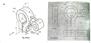
- 3. 3.40 Unit 2 Chapter 3:OrthographicProjections Engineering Graphics by P. H. JainSP 9. Fig. 3.99 (a) is an isometric view of an object. Draw a) Sectional Front View along section A-A Sectional Top Viewalong section B-B; A p10, 4holes b) c) R.H.S.V. Solution: Refer fig. 3.99 (b). 10 A A RH.S.V. - 30 Sectional! F.V. 50 18 - 10-30- B R25 30- 2 -32 -72 18 Fig.3.99(6) 50- SectionalT.V x Fig. 3.99 (a)
- 4. EngineeringGraphicsby P.H.Jain SP 3-5. Fig. 3.93 (a) Fig. 3.95 (a) shows isometric view of objects. Drawtheir: a) Sectional E.V. (along section A-A); Unit 2 Chapter3:Orthographic Projections 3.38 b) Top View c) R.H.S.V. Solution:Referfig.3.93 (b)- fig. 3.95 (b). 3. 2- 50 PP V ectionalV HP RHS R 30 60 - 9 0 2 5 5 0 Fig. 3.93 (a) Fig 3.93(6 TV ***wwww.wwww.Wwww.WK w* **** www.www A