Communication System Components in <40 Characters
•Download as PPT, PDF•
0 likes•91 views

Enjoy

Recommended
More Related Content
What's hot
What's hot (20)
Similar to Communication System Components in <40 Characters
Similar to Communication System Components in <40 Characters (20)
More from Ridwanul Hoque
More from Ridwanul Hoque (20)
Recently uploaded
Recently uploaded (20)
Communication System Components in <40 Characters
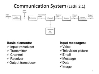
- 1. Communication System (Lathi 2.1) 1 Basic elements: Input transducer Transmitter Channel Receiver Output transducer Input messages: Voice Television picture Email Message Data Image
- 2. 2 Communication System 2 Input Transducer: Converts the message to electrical signal (baseband signal) Microphone, keyboard, camera etc. Bandwidth of the base band signal – depends on the type of input message System design depends on the type of input message Bandwidth of an information signal is the difference between the highest and the lowest frequency contained in that signal
- 3. 33 Communication System 3 Transmitter: Process the baseband signal to a suitable form for transmission over a channel Consists of several sub-systems: A/D converter, modulator, encoder etc. Consists of oscillators, amplifiers, tuned circuits and filters, modulators, and other circuits Bandwidth of the transmitted signal – depends on the process in the transmitter
- 4. Communication System Channel: Transmission medium that conveys the transmitted electrical/electromagnetic signal to receiver Channel types: wired or wireless Wired: twisted copper wire (telephone, DSL), coaxial cable (television, internet), optical fiber (backbone) Wireless: Microwave (Satellite and cellular), RF wave (Cellular, WiFi, WiMax, LTE) 4
- 5. 5 Communication System Channel: Capacity: How much information can be sent in 1 s through a channel? Capacity depends on the bandwidth of the channel Bandwidth: Copper wire: 1 MHz, Coaxial cable: 100 MHz, Microwave/RF: GHz, Optical fiber: THz Attenuation, distortion, and noise are the main impairments Bandwidth of a communication channel is a difference between the highest and the lowest frequency that the channel will allow to pass through it Bandwidth of a communication channel must be equal or greater than the bandwidth of the information. 5
- 6. 6 Communication System Receiver: Process the received signal such that the input signal can be recovered Consists of several reversed sub-systems of transmitter: D/A converter, demodulator, decoder etc. Consists of oscillators, amplifiers, tuned circuits and filters, demodulators, and other circuits 6
- 7. 77 Communication System Output transducer: Convert the demodulated signal into output message (Voice, video, image, data, email etc.) Headphone, television, computer etc. are the output transducer 7
- 9. 9 Mathematical Models of Sources A source is stationary if {Xi} is stationary memoryless if Xi and Xj are independent for i ≠ j i.i.d. if {Xi} are i.i.d. (independent and identically distributed) continuous if A is a continuous set (e.g. the real numbers) discrete if A is a discrete set (e.g. the integers {0, 1, 2, . . . ,9}) binary if A = {0, 1}
- 10. 10 Mathematical Models of Sources Example: Discrete Memoryless Source (DMS) An information source: Alphabet A = {0, 1} p(Xi = 1) = p p(Xi = 0) = 1- p This is an example of a DMS Special case: when p = 0.5, the source is called a Binary Symmetric Source (BSS)
- 11. 11 Measure of Information • How much information does a message carry from the sender to the receiver? • Examples –Ex.1: Imagine a person sitting in a room. Looking out the window, she can clearly see that the sun is shining. If at this moment she receives a call from a neighbor saying “It is now daytime”. Does this message contain any information? – Ex. 2: A person has bought a lottery ticket. A friend calls to tell her that she has won first prize. Does this message contain any information?
- 12. 12 Measure of Information – Ex.1. It does not, the message contains no information. Why? Because she is already certain that is daytime. – Ex. 2. It does. The message contains a lot of information, because the probability of winning first prize is very small. • Conclusion The information content of a message is inversely related to the probability of the occurrence of that event If a message is very probable, it does not contain any information. If it is very improbable, it contains a lot of information. We need quantitative measure of information
- 13. 13 Measure of Information DMS: Alphabet set A = {a1, a2, . . . , aN } Probability mass function pi = p(X = ai) for all i = 1, 2, . . . , N Units: Self-information: The information revealed about each source output ai is defined as the self-information of that output Self-information: I(pi) = − log(pi )
- 14. 14 Measure of Information: Entropy Information content (Entropy) of a source: The weighted average of the self-information of all source outputs Note: 0 log 0 = 0 H(X) is a function of the PMF of the random variable X and is, therefore, a number Unit of H(X): Bits/sample
- 15. 15 Entropy H(X) The binary entropy function No information Maximum information
- 16. 16 What does H(X) Signify? The minimum average number of bits required to represent each sample without distortion The average information obtained by observing an outcome The average uncertainty about X before it is observed
- 17. 17 What does H(X) Signifies?
- 18. Challenges in Communication (Lathi 1.2) Channel impairments: attenuation, distortion, noise Receiver background noise The magnitude of the channel impairments depends on the type of channel Attenuation: Signal attenuation or degradation exists in all media Increases with distance Wireless medium has the highest attenuation -exponential decay Optical fibers have less attenuation, eg, 0.2 dB/km 18
- 19. Distortion: Signals distort during travel through medium (why?) Wire: frequency dependent attenuation => lowest distortion Optical fiber: Delay differences in different modes, frequency dependent attenuation, highest dispersion Wireless: Delay differences due to multi-path propagation, time dependent randomness of particles, frequency dependent attenuation => highest distortion Inter-symbol interference due to distortion 19 Challenges in Communication
- 20. Challenges in Communication Noise: Channel noise/ External noise Random, undesirable electronic energy that enters the communication system via the communicating medium and interferes with the transmitted message Interference from nearby channels, human made noise (automobile ignition radiation, microwave oven), natural noise (lightning) External noise can be minimized with proper design Receiver background noise/Internal noise Thermal noise and random emission in electronic devices One of the main problems in communication 20
- 21. 21 Electromagnetic Spectrum Electromagnetic spectrum is the range of all possible frequencies of electromagnetic radiation
- 22. 22 Radio Spectrum (3 kHz – 3 THz) *International Telecommunication Union (ITU): An UN organization which allocates global radio spectrum and satellite orbits For more details on the application areas: http://en.wikipedia.org/wiki/Radio_spectrum
- 23. 23 Signal Bandwidth Bandwidth: Measure of the frequency contents of an information signal Bandwidth of the base band signal – depends on the type of input message Speech Music
- 24. 24 Bandwidth (for baseband signal) 1. Absolute Bandwidth: is f2 – f1, where the spectrum is zero outside the interval f1< f <f2 along the positive frequency axis. |X(f)| 2B 0 Absolute Bandwidt h = B 2. 3-dB BW (Half-power BW): is f2 – f1 , where for frequencies inside the band f1< f < f2 , the magnitude spectra fall no lower than 1/2 times the maximum value, and the maximum value occurs at a frequency inside the band. |X(f)| 2B3dB 0 3dB Bandwidth B3dB -3dB 3. Equivalent Noise Bandwidth (Beq) is the width of a fictitious rectangular spectrum such that the power in that rectangular band is equal to the power associated with the actual spectrum over positive frequencies. |H(f)|2 2Be q 0 |H(0)|2
- 25. 25 Bandwidth (for baseband signal) 4. Null-to-null BW (zero-crossing BW) Bn: is f2 – f1, where f2 is the first null frequency in the envelope of the magnitude spectrum above f0 and f1 is the first null in the envelope below f0. Here f0 is the frequency where the magnitude spectrum is a maximum. For baseband systems, f1 is zero. |X(f)| 2Bn 0 5. Bounded Spectrum Bandwidth: is f2 – f1 where outside the band f1 < f < f2, the PSD, which is proportional to |H(f)|2, must be down by at least a certain amount, say 50 dB, below the maximum value of the power spectral density. 6. X% Power Bandwidth: is f2 – f1, where f1 < f < f2 defines the frequency band in which x% of the total power resides. (100-x)% of the total power is outside the bandwidth.
- 26. 26 Typical Channel Bandwidth Bandwidth of a communication channel is the difference between the highest and the lowest frequency that the channel will allow to pass through it Bandwidth of a communication channel must be equal or greater than the bandwidth of the information Copper wire: 1 MHz Coaxial cable: 100 ~ 500 MHz Microwave/RF: GHz Optical fiber: THz
- 27. 27 Twisted Pair Copper Cable Least expensive and widely used Two insulated copper wires arranged in regular spiral pattern Number of pairs are bundled together in a cable Limited in terms of data rate and distance Requires amplifiers every 5-6 km for analog signals and repeaters every 2-3 km for digital signals Attenuation is a strong function of frequency: Higher frequency implies higher attenuation Susceptible to interference and noise Twisting reduces the tendency to radiate radio frequency noise as the radiations from twisted wires cancel each other Twisting also decreases the crosstalk/EMI between adjacent pairs in the cable Unshielded twisted pair (UTP): • Speed between 10-100 Mbps • Susceptible to crosstalk Shielded twisted pair (STP): • Supports higher data rate than UTP • Less susceptible to crosstalk
- 28. 28 Coaxial Cable Most common due to inexpensive, light, flexible and easy to work with Contain two conductors sharing common axis: a central conductor wire and a surrounding outer conductor/shield serving as ground Less susceptible to interference and noise as the outer conductor blocks EMI Support higher data rates and longer distance than twisted pair cable Requires amplifiers and repeaters for every few kms for analog and digital transmissions respectively Superior frequency characteristics compared to twisted pair
- 29. 29 Optical Fiber Dielectric waveguide that uses pulse of light instead of electrical signals Thin and flexible material to guide optical rays Cylindrical cross-section with three concentric links: Core, Cladding and Jacket Advantages: Much higher bandwidth (theoretically 2 x 10¹³ Hz): can carry hundreds of Gbps over tens of kms Smaller size and light weight Significantly lower attenuation (as low as 0.2dB/km): Greater repeater spacing Not affected by external EM fields, i.e., not vulnerable to interference, impulse noise, or crosstalk Ruggedness and flexibility
- 30. 30 Wireless Media No use of wire: use Earth’s atmosphere to act as transmission media Transmission and reception are achieved using antenna Transmitter sends out the EM signal into the medium Receiver picks up the signal from the surrounding medium Supports mobility and flexibility Convenient in use Lower capital and operating expenditure compared to wired networks Connection quality vary randomly with time due to fading Susceptible to multi-user interference Less secured Network management more complex High attenuation
- 31. 31 Channel Characteristics Propagation constant Attenuation constant, α : Determines the attenuation of a signal of frequency ω over a unit distance Phase constant, β: Determines the phase change (delay) in a signal of frequency ω over a unit distance
- 32. 32 Channel Characteristics For distortionless transmission: Transmission is said to be distortion less if the input and output have identical wave shapes: (i) amplitudes of all the frequency components are multiplied by the same factor, and (ii) all the frequency components are delayed by the same amount. Thus, in distortion-less transmission, the input x(t) and output y(t) satisfy the condition: y(t) = Kx(t - ) => Y(ω) = KX(ω)e-jω = KX(ω)ej(ω) where is the delay time and K is a constant. K |H(ω)| = α ω Amplitude response - ω (ω) = - ω = -β ω Phase response Equalizer can be used for minimize attenuation and phase distortions Phase delay: p= - (ω)/ω = β/ω Group delay: g = - d(ω)/dω = dβ/dω
- 33. Capacity of a Transmission Link (Lathi 1.3) Shannon's limit, C = B log2 (1 + SNR) bits/second C = capacity, B = channel bandwidth SNR = signal-to-noise ratio=Received Signal Power/ Noise Power Capacity increases linearly with bandwidth, but only logarithmically with signal strength Shannon's limit tells us what we can achieve it tells us nothing about how to do it Two primary resources in communications Transmitted power (should be green) Channel bandwidth (very expensive in the commercial market) 33
- 34. Calculation of Power and SNR SNR (dB)= 10 log10(Pr/N) Pr = received signal power in watt N=noise power in watt Unit of power: watt or dBm dBm is used for low power Power in dBm = 10 log10 (Power in watt * 1e3) Power in watt= 10^(Power in dBm/10)*1e-3 34
- 35. 3535 Layering Architecture (Haykin ch 1) Concept of layering is used in our daily life Communication through air mail
- 36. 3636 Why Layering? Layer architecture simplifies the communication network design It is easy to debug network applications in a layered architecture network The communication system management is easier Research/work on a layer can be done independently
- 37. 3737 OSI Model International standard organization (ISO) established a committee in 1977 to develop an architecture for computer communication Open Systems Interconnection (OSI) model is the result of this effort In 1984, OSI model is approved as reference model
- 38. 3838 OSI Model
- 39. 3939 Physical layer Provides physical interface for transmission of information through a medium (wired/wireless) Covers all - mechanical, electrical, functional and procedural - aspects for physical communication
- 40. 4040 Data Link Layer Who will transmit, when to transmit, whom to transmit to Attempts to provide reliable communication over the physical layer interface in one hop distance
- 41. 4141 Network Layer The network layer is responsible for the delivery of individual packets from the source host to the destination host Determine the route for the packets
- 42. 4242 Upper Layers Transport Layer Controls congestion Provides transmission reliability between source and destination Session Layer The session layer is responsible for dialog control and synchronization Presentation Layer Translate, encrypt and compress data Application Layer Allows access to network resource Make applications into data format
- 43. 43 43 Interaction among the layers
Editor's Notes
- super high frequency, (SHF), 10, (~1010 Hz), 3, –, 30 GHz, 100, –, 10 mm.extremely high frequency, (EHF), 11, (~1011 Hz), 30, –, 300 GHz, 10, –, 1 mm.tremendously high frequency, (