size reduction and size separation.pptx
•Download as PPTX, PDF•
0 likes•44 views

size reduction

Recommended
More Related Content
Similar to size reduction and size separation.pptx
Similar to size reduction and size separation.pptx (20)
More from Rahul kumar
Recently uploaded
Recently uploaded (20)
size reduction and size separation.pptx
- 2. Introduction The terms crushing and grinding usually signifies subdividing to greater or less content. Few materials exist in optimum size and most materials must be comminuted or size reduced at some stage during production of dosage form Milling is the mechanical process of reducing the particle size of solids Milling equipment is usually classified as coarse, intermediate or fine according to the size of the milled product
- 6. Size is conventionally expressed in terms of mesh (number of openings per linear inch of a screen) Coarse milling produces particles larger than 20 mesh, intermediate milling produces particles from 200-20 mesh (74-840 microns) and fine milling produces particles less than 200 mesh A given mill may operate in more than one class: a hammer mill may be used to prepare a 16 mesh granulation and to mill a crystalline material to 120 mesh powder
- 7. Pharmaceutical applications The surface area per unit weight known as the specific surface is increased by size reduction This affects the therapeutic efficacy of drugs that have low solubility in body fluids; eg- control of fineness of griseofulvin led to an oral dosage regimen half that of the original product Control of particle size and specific surface influences the duration of adequate serum concentration, rheology and product syringeability of a suspension of penicillin G procaine for intramuscular injection
- 8. The rectal absorption of aspirin from theobroma oil suppository is related to particle size Increased antisepetic action has been observed for calomel ointment when the particle size of calomel is reduced Size of particles used in inhalation aerosols determines the position and retention of the particles in the pulmonary system Size may affect texture, taste, rheology of oral suspensions besides absorption
- 9. The time required for extraction is shortened when the drug is size reduced due to increase in surface area due to increased area of contact between the solvent and solid and reduced distance the solvent needs to penetrate into the material. The time required for dissolution of chemicals to prepare solutions is shortened by use of smaller particles Drying may also be facilitated by milling which increases the surface area and reduces the distance the moisture must travel within the particle to reach the outer surface
- 10. Theory of comminution Strain and stress: When any solid body is subjected to opposing forces, there is a finite change in its geometry depending upon the nature of the applied load The relative amount of deformation produced by such forces is called strain The ratio of the forces F necessary to produce this strain to the area over which it acts is called the stress The three types of strain: Tensile strain Compressive strain Shear strain
- 11. The behaviour of solids which under stress are strained and deformed as shown in the stress- strain curve The initial linear portion is defined by Hooke’s law (stress is proportional to strain) and Young’s modulus (slope of linear portion) expresses the stiffness or softness in dynes per sq cm The curve becomes non linear at the yield point which is a measure of the resistance to permanent deformation
- 13. With still greater stress the region of irreversible plastic deformation is reached. The area under the curve represents the energy of fracture and is an approximate measure of impact strength of the material Size reduction begins with the opening of any small cracks that were initially present Thus larger particles with numerous cracks fracture more readily than smaller particles with fewer cracks
- 14. If the force of impact does not exceed the elastic limit (Hooke’s law region) the material is reversibly deformed or stressed A force that exceeds the elastic limit fractures the particle A flaw in a particle is any structural weakness that may develop into a crack under strain Any force of milling produces a small flaw in the particle
- 15. The useful work in milling is proportional to the length of new cracks formed A particle absorbs strain energy and is deformed under shear or compression until the energy exceeds the weakest flaw and causes fracture of the particle The strain energy required for fracture is proportional to the length of the crack formed since the additional energy required to extend the crack to fracture is supplied by the strain energy to the crack
- 16. Griffith theory of cracks and flaws assumes that all solids contain flaws and cracks which increase with applied force according to the crack length and focus the stress at the atomic bond of the crack apex where T is tensile stress, Y is Young’s modulus, Ꞓ is the surface energy of the crack wall and c is the critical crack depth required for fracture The immediate objective of milling is to form cracks that spread through the deformed particles at the expense of strain energy and produce fracture
- 17. The useful work is directly proportional to the new surface area Since the crack length is proportional to the square root of the new surface area produced, the useful work is inversely proportional to the square root of the product diameter minus the feed diameter. The energy E’ required to produce new surface area is: Where D1 is the diameter of the feed material, D2 is the diameter of the product discharged from the
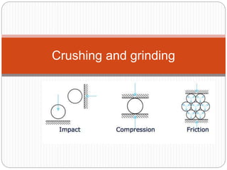
- 19. Types of mills A mill consists of three basic parts: Feed chute which delivers the material Grinding mechanism usually with a rotor and a stator Discharge chute The principle of operation depends on direct pressure, impact from a sharp blow, attrition and cutting In most mills the grinding effect is a combination of these actions
- 22. Classification of crushing and grinding machinery 1. coarse crushers (a) Jaw crushers- i) Blake ii) Dodge 2. Intermediate (a) Rolls (b) Disc crushers (c ) Edge runners (d)Disintegrators (e ) Hammer mills 3. Fine grinders (a) Centrifugal- i) Raymond (b) Buhrstones (c ) Roller mills (d) Ball mills and tube mills (e ) Ultrafine grinders
- 23. If the milling operation is such that the material is reduced to the desired size by passing it once through the mill, the process is called open-circuit milling A closed-circuit milling is one in which the discharge from the mill is passed through a size separation device or classifier and the oversize particles are returned to the mill for further reduction in size
- 25. Hammer mill It is an impact mill using a high speed rotor (upto 10,000 rpm) to which a number of swinging hammers are fixed The material is fed at the top or centre, thrown out centrifugally and ground by impact of the hammers or against the plates of the casing The clearance between the housing and hammers cause size reduction
- 28. The material is retained until it is small enough to fall through the screen that forms the lower portion of the casing Use: it is used to mill almost any type of material, like dry materials, wet filter cakes, ointments, and slurries Brittle materials are best fractured by impact from blunt hammer while fibrous materials are best reduced in size by cutting edges
- 29. Advantages Hammer mills are compact with a high capacity Size reduction of 20-40 microns may be achieved Hammer mills are simple to install and operate The speed and screen can be rapidly changed They are easy to clean and may be operated as a closed system to reduce dust and explosion hazards
- 30. Ball mill It consists of a horizontal rotating hollow vessel of cylindrical shape with the length slightly greater than its diameter The mill is partially filled with balls of steel or pebbles which act as the grinding medium If pebbles are used then it is called pebble mill If rods/bars are used then it is called rod mill Rod mill is suitable for sticky materials which would hold the balls together because greater weight of the rods causes them to pull apart
- 31. The tube mill is a modified ball mill in which the length is about four times that of the diameter and the balls are smaller than in a ball mill As the material remains in the longer tube mill for a greater length of time the tube mill grinds more finely than the ball mill Operation of ball mill In a ball mill, rotating at a slower speed the balls roll and cascade over one another providing attrition As the speed is increased, the balls are carried up the sides of the mill and fall freely onto the material with an impact action which is responsible for most of the size reduction
- 33. Ball milling is thus a combination of impact and attrition If the speed is increased sufficiently, the balls are held against the mill casing by centrifugal force and revolve with the mill The critical speed of the ball mill is the speed at which the balls just begin to centrifuge with the mill Thus at critical speed, the centrifugal force is equal to the weight of the ball and the critical
- 34. At and above the critical speed, no significant size reduction occurs Nc= 76.6/√D where D is the diameter of the mill in feet Ball mills are rotated from 60-85% of the critical speed For optimum speed, the empirical rule is: n=57- 40 logD where n is the speed in revolutions per minute and D is the inside diameter of the mill in feet
- 35. The smaller balls give slower but finer grinding The optimum diameter of a ball is app proportional to the sq root of the size of the feed: Dball 2=kD where, Dball and D are the diameters of the ball and the feed particles, respectively If the diameters are expressed in inches then k may be the grindability constant varying from 55 for hard materials to 35 for soft materials To operate effectively, a ball charge of 30-50% of the volume of the mill is required
- 36. Advantages The ball mill may be used for dry or wet milling May be used for batch or continuous operation: for unstable or explosive materials in batch operation, the milling chamber may be sealed with an inert atmosphere and ground Ball mills may be sterilized and sealed for sterile milling for production of ophthalmic and parenteral products The installation, operation and labor costs are low It is unmatchable for fine grinding of hard, abrasive
- 37. Fluid energy mill/micronizer The material is suspended and conveyed at high velocity by air or steam, which is passed through nozzles at 100-150 psi The violent turbulence of the air and steam reduces the particle size by interparticular attrition Air is used as most drugs are thermo labile or have low melting points As compressed air expands at the orifice the cooling effect counteracts the heat generated by milling
- 39. The material is fed near the bottom of the mill through a venturi injector As the compressed air passes through the nozzles, the material is thrown outward against the wall of the grinding chamber and other particles The air moves at high speed in an elliptical path carrying with it fine particles that pass out of the discharge outlet into a cyclone separator and a bag collector The large particles are carried by centrifugal force to the periphery where they are exposed to attrition action
- 40. The mill provides internal classification which permits the finer and lighter particles to be discharged and the heavier oversized particles under the effect of centrifugal force to be retained until reduced to a small size The mill reduces the particle to 1-20 microns The feed should be pre-milled to app 20-100 mesh size to facilitate milling
- 41. Cutter mill Cutting mills are used for tough, fibrous materials and provide a successive cutting or shearing action rather than attrition or impact The rotary knife cutter has a horizontal rotor with 2-12 knives spaced uniformly on its periphery turning from 200-900 rpm and a cylindrical casing having several stationary knives The bottom of the casing holds a screen that controls the size of the material discharged from the milling zone
- 43. The feed size should be less than 1 inch thick and should not exceed the length of the cutting knife The size limit of a rotary cutter is 80 mesh Roller mills They consist of 2-5 smooth rollers operating at different speeds , thus size reduction is effected by a combination of compression and shearing action
- 44. Colloid mill A colloid mill consists of a high speed rotor (3000- 20,000 rpm) and stator with conical milling surfaces between which is an adjustable clearance ranging from 0.002-0.03 inches The rotor speed is 3000-20,000 rpm The material to be ground should be pre-milled as finely as possible to prevent damage to the colloid mill Use: to process suspensions and emulsions, not used for dry materials
- 46. The premilled solids are mixed with liquid vehicle before being introduced into the colloid mill Interfacial tension causes part of the material to adhere to and rotate with the rotor Centrifugal force throws part of the material across the rotor onto the stator At a point between the rotor and the stator, the motion imparted by the rotor ceases and hydraulic shearing force exceeds the particle-particle attractive forces which cause aggregates
- 47. In emulsification, a clearance of 75 microns may produce a dispersion with average particle size of 3 microns The milled liquid is discharged from an outlet in the periphery of the housing and may be recycled
- 48. Edge runner mill
- 52. Factors for selection of mill The choice of a mill is based on: Product specifications (size range, particle size distribution, shape, moisture content, physical and chemical properties) Capacity of the mill and production rate requirements Versatility of operation (wet and dry milling; change of speed, screen, safety features, etc)
- 53. Dust control (loss of costly drugs, health hazards, plant contamination) Sanitation (ease of cleaning, sterilization) Auxiliary equipment (cooling system, dust collectors, forced feeding, stage reduction) Batch or continuous operation Economical factors (cost, power consumption, space occupied, labor cost)
- 54. Size separation Separation of solids on the basis of size It deals with methods of determining size distribution of sample by screen analysis followed by methods of for separating dust from gas streams Standard screens Various standard screens have been proposed in which both the diameter of the wire and the number of meshes per inch (mesh=openings across one linear inch of screen) are specified so as to give a definite ratio between the openings in one screen and the next succeeding screen in the series
- 55. One common set of standard screens is the Tyler standard screen scale This is based on a 200-mesh screen with wire 0.0021 in. in diameter giving a clear opening 0.0029 in. square Succeeding coarser screens have their mesh and wire diameter so adjusted that the area of the opening in one screen is approximately twice the area of the opening in the next finer screen
- 56. This means that the linear sizes of the openings in any two successive screens have the ratio of 1:√2 Normally 200 mesh is the smallest screen Another common specification for standard screens is the US standard This uses the Tyler 200-mesh standard as a basis but differs slightly in other sizes
- 57. Screen analysis Screen analysis of a material is carried out by placing a sample on the coarsest of a set of standard screens Below the coarsest screen are placed a series of screens in the order of decreasing size of mesh The pile of screens with the sample on the top screen is shaken in a definite manner, either manually or mechanically for a definite length of time and the material collected on each screen is removed and weighed
- 60. A sample screen analysis is given in the table The first and fourth columns are the experimental data The second column gives the nominal screen opening in microns The third column gives the average particle size of the fraction retained on each screen, calculated as the arithmetic mean of the two screen openings used to obtain the fraction Eg- the material which passed through 14 mesh screen (1168 microns) and retained on 20-mesh screen (833 microns) has an average particle size
- 61. The graphical presentation of the screen analysis may be made in a variety of ways, like: The weight percent of material retained plotted vs the average particle size called a frequency-size distribution plot Fraction of total weight of particles having a size greater than or less than a given screen opening called the cumulative size distribution curves Plotting the log of screen aperture vs cumulative percent undersize/oversize we get the log- probability plot
- 62. Wire screen Screen may be obtained in a variety of meshes in a variety of weights for any given mesh In most screens, the wire is a double crimp that helps to preserve the allignment of the wires The ordinary screen usually has the same number of meshes per inch in both directions
- 63. Types of screening equipment Since screens may be called upon to pass grains ranging from several inches in diameter to 200 mesh various types of screening equipment have been developed differing in ruggedness, method of moving the material across them and materials of construction Based on size of material, we have: Grizzlies: used for coarse screening of large lumps and are of rugged construction Trommels: rotating screens used for fairly large particles Shaking and vibrating screens used for fine sizing
- 64. Grizzly: it is a simple device consisting of a grating made of bars usually built on a slope across which material is passed The slope and the path of the material is parallel to the length of the bars The bar is shaped such that the top is wider than the bottom so that the bar can be made fairly deep for strength without being choked by particles It is often constructed in the form of a short endless belt so that the oversize is dumped over the end while the sized material passes through It is used for only coarsest and roughest separations
- 66. Trommels It consists of a rotating cylinder of perforated sheet metal or wire screen It is open at one or both ends and the axis of the cylinder is horizontal or slightly inclined so that the material is advanced by the rotation of the cylinder It is best suited for relatively coarse material (1/2 in over) Shaking screen Many size separations in which product may be from ½ in down to almost the finest sizes that can be handled by screens, may be performed by means of flat or slightly inclined screens that are given a reciprocating motion
- 67. Trommel
- 69. The frame is of channel irons suspended by hanger rods so that it can move freely It is shaken by means of an ordinary eccentric on a rotating shaft The screen cloth may be riveted directly to the frame or it may be soldered over a light removable frame bolted into place Vibrating screens In some cases instead of giving the screen a shaking or a reciprocating motion, the screen is vibrated to keep the particles moving and to prevent blinding This vibration may be accomplished by attaching to the screen cloth, pins that pass through the screen
- 72. Rotating shafts on the outside of the casing carry hinged hammers that strike these pins Another method is to place one or two light channels or other form of bearing surface on the underside of the screen frame These channels rest on cams attached to rotating shafts One of the well known type is the Hum-mer, another example is Rotex
- 73. Air separation methods- Cyclone separators Cyclones are mainly used for the separation of solids from fluids and utilize centrifugal force to effect the separation Such a separation depends not only on particle size but also on particle density so that cyclones may be used to effect a separation on the basis of particle size or density or both It consists of a short vertical cylinder closed by a flat or dished plate on top and by a conical bottom The air with its load of solid is introduced tangentially at the top of the cylindrical portion Centrifugal force throws the solid particles out against the wall and they drop into the hopper
- 75. The outlet for the air is usually in the centre of the top and is also usually provided with a duct that extends inwardly into the separator to prevent the air short-circuiting directly from the inlet to the outlet Such separators are widely used for collecting of wood chips; heavy and coarse dusts and all manner of separations in which the material to be removed is not too fine They may also be used for separating heavy or coarse materials from fine dust
- 76. Air separators The cyclone alone cannot carry size separations on fine materials For such separations a current of air combined with centrifugal force is used The feed enters at A and falls on to the rotating plate B. Driven by the same shaft is a set of fan blades C which produce a current of air as shown by arrows Fine particles are picked up by the draft and carried into the space D where the air velocity is sufficiently reduced so that they are dropped and removed at E Particles too heavy to be picked up by the air stream fall to the bottom and are removed at F
- 78. Size separation by settling When size separations are to be carried out on particles too small to screen effectively, or where very large tonnages are to be handled methods involving differences in the rates of settling of particles of different sizes and of different materials are used Eg: two particles of different settling rates in water are placed in an upward-flowing water stream; if the velocity of the water is adjusted, the slower particle will be carried upward, the faster particle will move downward and a separation is attained
- 80. The settling rate of particle also depends on shape and density besides size Classification apparatus may involve simple settling or settling aided by mechanical devices It may operate only on water entering with the pulp or additional water may be supplied, called hydraulic water If the apparatus is to settle out all the solids introduced and give a clear overflow, the process is called sedimentation The Dorr thickener is an equipment for sedimentation
- 81. General laws of settling-free settling Say a spherical particle of density ρs and diameter D, starting from rest and settling in a stagnant fluid of density ρ and viscosity μ. The bulk of the fluid with respect to the particle is assumed to be large- the distance of the particle from the vessel wall or any other solid must be atleast 10-20 particle diameters These conditions define the process called free settling The particle will accelerate under gravity As it accelerates the fluid offers a greater frictional resistance At a point of time, the resisting force=gravitational force and the acceleration is zero
- 82. From this time onwards, the particle will settle at a definite constant velocity Let this velocity be ut, called the terminal settling velocity Now, the resistance offered by a fluid to a solid body in motion relative to the fluid is given by: Where, F=total resisting force; A= Area of solid in contact with the fluid; u= velocity of fluid past body; ρ =density of fluid; μ = viscosity of fluid; φ’= a function which is determined experimentally
- 83. Since the area of a sphere projected on a plane normal to the direction of motion is πD2/4 When the velocity u reaches the terminal value, the resisting force F=force of gravity Since the volume of the particle is proportional to the cube of diameter
- 84. Equating the force of gravity to the resisting force, Viscous resistance; Stoke’s law Stokes derived a relationship for the resistance offered to the motion of a sphere in a fluid under such conditions that the entire resistance is caused by the internal friction of the fluid and inertial effects are negligible This relationship applies to the laminar-flow region and may be expressed as:
- 85. Substituting Eq This relationship is called Stoke’s law has been shown to be valid for Reynold’s numbers less than 0.1