SlideShare a Scribd company logo
1 of 5
Download to read offline
Oct. 20, 1964 , R. E., TANCINCO 3,153,766
MODE OF OPERATION OF THE FENTODE OR TETRODE TUBE
IN THE OUTPUT STAGE OF AN AUDIO POWER AMPLIFIER
Filed Sept. 8, 1961
ANODE CATHOD
YAN A/
DODE INVENTOR.
FIG.5 -N
(ewi? Sauveto
UnitedStates Patent Office 3,153,766
Patented Oct. 20, 1964
3,553,766
MODE OF OSPERATION OF THE PENTO DE OR
TETRODE TUBE IN THE OUTPUT STAGE OF
AN AUDIO POWER AMPLEFER
Renato E. Tancinco, Meycauayan, Bulacan, Philippines
Fied Sept. 8, 1961, Ser. No. 36,817
Claims priority, application Philippines Sept. 2, 1960
5 Claims. (C. 330-22)
This invention relates to a new concept in the mode
of operation of a pentode or tetrode power tube in the
output stage of an audio frequency amplifier. Up to
the present stage of the art, the output tubes in an audio
frequency amplifier operate only under one set of char
acteristics which is determined by the mode of opera
tion assigned to them. The following are the modes of
operations under which a pentode or tetrode power tube
may be made to operate:
(1) Triode connected pentode or tetrode output stage.
(2) Distributed load pentode or tetrode output stage or
the so called "Uutra Linear Amplifiers.'
(3) Straight pentode or tetrode output stage.
(4) Unity coupled output stage.
(5) “Extended Class A Amplifier” using a pair of triode
connected push pull pentode or tetrode in parallel
with another pair of the same type of tubes con
nected as straight pentode or tetrode.
The sixth mode of operation is offered by the under
signed and is the subject of this patent application. In
this new mode of operation, the output pentode or
tetrode tube alternately operates between the two sets
of characteristics assigned to them. These two sets of
characteristics are determined by the position of the two
taps on the plate winding of the output transformer to
which the anodes of the back to back connected diodes,
feeding the screen grid of the said power tube, are con
nected. The particular set of characteristics under which
the output tube operates is determined by the polarity
of the grid signal voltage relative to the quiescent poten
tial of the control grid, otherwise known as the grid bias.
Some of the objectives of this invention are as follows:
(1) To obtain high quality reproduction of sound with
out the necessity of using expensive special output
transformers or resorting to complex circuitry.
(2) To be able to obtain the most power output avail
able for a given power output tube and a given B
supply voltage, commensurate with high plate circuit
efficiency, low distortion, and low power consump
tion during the absence of signal or during idling.
(3) To attain the above objectives without the neces
sity of using more than one pair of power output tubes
or more than one power Supply or B-Supply.
(4) To reduce the output impedance of the power out
put stage before the application of any inverse feed
back.
(5) To be able to attain the above objectives without
the need for very high signal grid drive voltage to the
power output tubes.
(6) To give the amplifier designer a free hand in the
design of the whole amplifier. The said freedom is
achieved by virute of the following:
(a) Absence of inherent inverse feedback in the
output stage. The manner of application of the
inverse feedback is left entirely to the amplifier
designer.
(b) The designer is free to choose any type of
pentode or tetrode power tube for the power
amplifier stage.
(c) The choice of the position of the taps on the
plate winding of the output transformer is the
0.
5
20
25
30
35
40
45
50
55
60
65
70
2
privilege of the amplifier designer. The positions
chosen will determine the two different sets of
characteristics between which the power output
tube will alternately operate.
The New Circuit
A good amplifier must not only be good in perform
ance but it must meet the requirements of the manu
facturer, the amplifier designer, and above all satisfy the
ultimate user, i.e., the owner.
it is a fact that in the reproduction of music, the
high power peaks are relatively few and of very short
durations, that, most of the time the amplifier may be
considered as idling. Low consumption of power dur
ing idling is therefore of paramount importance. An
amplifier is usually rated at the maximum power that it
can deliver during these peaks, with a minimum of dis
tortion and good stability. The maximum power that
a pair of power tubes can deliver is usually limited by
the maximum plate dissipation rating of the said power
tube. To get therefore the most out of a pair of power
tubes, the plate circuit efficiency of output stage should
be high. It is also very desirable to obtain high power
outputs without the necessity of using very high signal
grid drive voltages. In other words, the power sensi
tivity of the output stage must be high. It is therefore
clear that Class B operated pentode or tetrode power
tubes appear to be ideal for the output stage. The re
quirement of low distortion in output stages using the
conventional Class B pentode or tetrode power tubes is,
however, not easily met. The cause is the presence of
a form of distortion, called the notch distortion, which
occurs as a notch or fuzziness in the output signal wave
form. In reality, this fuzziness in the output signal
waveform is a form of shock excited self oscillation at
some ultra-sonic frequency in the plate winding of the
output transformer. The leakage inductance between
the plate windings of the output transformer forms an
oscillatory circuit in combination with the winding
capacitance and other stray capacitances. This oscil
latory circuit is shock excited into self-oscillation every
time the plate current of the power tube is driven to
cut off. Unfortunately the frequency of this fuzziness
or notch distortion is so high that it is beyond the effec
tive control of the inverse feedback loop that may be
applied in the amplifier. Furthermore, the plate cur
rent of the power tube which is the most logical part
of the amplifier that can prevent the said distortion, has
been driven to cut off. The said power tube, being then
inactive, is therefore not in a position to prevent the
occurrence of the said notch distortion. So far there
are two successful solutions to the problem of prevent
ing the occurrence of the notch distortion. They are
exemplified in the Unity Coupled Amplifiers and the
Extended Class A amplifiers. A third solution is offered
by this invention, which is believed to be an entirely
new concept in the mode of operation of pentode or
tetrode power tubes in the output stage of an audio power
amplifier. -
The foregoing objectives will become more apparent
from the following detailed description of various em
bodiments of the invention and from the accompanying
drawings wherein:
FIG. 1 is an electrical schematic diagram illustrating
a push-pull tetrode power amplifier incorporating the
switching diodes in circuit between the screen grids and
output transformer.
FIGS. 2-4 are views similar to FIG. 1 but illustrating
various modifications for connecting in the switching
diodes; and
FIG. 5 is a detail of one of the switching diodes in
3,153,766
d
dicating the convention observed in designating its cath
ode and anode components.
Referring to FIG. 1 of the annexed drawing which
forms a part of this patent application, there is shown a
push pull tetrode power amplifier, which is operated as
a conventional Class B output stage except for the man
ner in which the screen grids of the power tetrodes
V-a and V-b are fed. In a conventional output stage
using Class B pentodes or tetrodes, the screen grids of
the tubes are fed by the B-Supply for the plates or, if
a different voltage is required for the screen grids, by a
separate screen grid power supply. It will be noticed
that the screen grids of the power tetrode tubes V-a
and V-b are connected to the common cathodes of two
pairs of back to back connected diodes, V-, V-2, V-3
and V-4. The anodes of the diodes V- and V-2 are
connected respectively to taps No. 1 and No. 2 on the
corresponding plate winding of the output transformer
T-1 and similarly the diodes V-3 and W-4. When the
tetrode V-a grid is driven to the positive direction by
the signal, the plate swings to the negative direction
relative to the B-Plus terminal of the B-Supply. Such
a situation makes tap No. 2 on the plate winding more
positive than the tap No. 1, causing diode V-1 to cut
off -while diode V-2 remains conducting. Diode V-2
therefore, effectively ties the screen grid to tap No. 2
on the plate winding. Tube V-a will therefore behave
in the same manner as when its screen grid is per
manently connected to tap No. 2 of the plate winding of
the output transformer. On the negative half of the
signal wave, the grid of the power tetrode V-a is driven
to the negative direction. The plate of the tube V-a
then swings to the positive direction relative to the B
Plus terminal of the B-Supply. Tap No. 1 therefore
of the plate winding of the output transformer then
becomes more positive than tap No. 2, thus causing
diode V-2 to cut off and diode V-E to conduct instead.
The conduction of diode V-1 effectively ties the screen
grid of tube V-a to tap No. 1 in plate winding of the out
put transformer T-1. Tube V-a then, will therefore be
have as if its screen grid is permanently connected to
tap No. 1 of the plate winding of the output transformer.
In the absence of a signal, the two diodes V-1 and V-2
are both conducting and are sharing the screen grid cur
rent drain of the tube V-a. It can be seen therefore
that the characteristics of the power tetrode V-a during
the positive half of the grid signal voltage is entirely
different from those, during the negative half of the grid
signal voltage. The tube V-a therefore automatically
operates alternately between two different sets of char
acteristics, with the aid of diodes V-1 and V-2. The
polarity of the grid signal voltage determines under
which set of characteristics the power tetrode V-a will
operate. It must be noted however that the positions of
taps No. 1 and No. 2 on the plate winding of V-a are
identical respectively to those of the taps No. 4 and No.
3 on the plate winding of V-b. The proper positions
of the taps on the plate windings are left to the discretion
of the amplifier designer. They can be anywhere from
the B-Plus terminal to the plate terminal of the plate
windings. The limiting positions of the taps is shown
in FIG. 2 of this drawing. Here, tap No. 1 is at the
plate terminal of the plate winding of the output trans
former while the tap No. 2 is at the B-Plus terminal of
the B-Supply. In FIG. 2 of the drawing, power tetrode
V-a operates as a straight tetrode on the positive halves
of the grid signal voltage, while during the negative
halves, it operates as a triode. On the positive half of
the grid signal voltage, the screen grid of tube V-a is
tied to the B-Plus terminal of the B-Supply while on the
negative half of grid signal voltage, the screen grid is
connected to its plate. Automatic Switching is ac
complished by the back to back connected diodes V-1
and V-2. In this mode of operation, the output trans
O
5
20
30
35
40
45
50
55
60
65
70
4.
former T-2 can be any standard output transformer
ordinarily available. Even though tube V-a is biased
to the projected plate current cut off value like in con
ventional Class B amplifiers, its plate current can never
reach cut off. The action of the control grid in forcing
a plate current cut off during the negative halves of
the grid signal voltage, is effectively counteracted by the
rise in the potential of the screen grid which is then
tied to the plate due to the conduction of diode V-1.
The low plate impedance of the then triode connected
V-a effectively damps the plate winding connected to
it, thus preventing the winding from ever being shock
excited into self-oscillation. The possibility therefore,
of the occurrence of notch distortion, can entirely be
precluded. The fact, that the tube V-a is connected
as a tetrode during the positive halves of the grid
signal voltage, makes it possible to obtain a relatively
large power output at high plate circuit efficiency and
at very low power consumption during idling, like in
the conventional Class B tetrode power amplifiers. We
therefore have now an amplifier that performs very
much like a conventional Class B tetrode amplifier with
all its advantages but without its disadvantages, i.e., the
notch distortion. It should be noted however, that the
grid drive voltage requirements are low and are the same
as when the output tubes are connected as in a conven
tional Class B tetrode power amplifier.
In the prototype amplifier that was tried by the under
signed a pair of 807's were used for V-a and V-b and
one pair of 6 x 4's were used in place of the diodes
V-A, V-2, V-3 and V-4. The common cathodes of the
6 x 4's feed the screen grids of the 807's. The output
transformer used was a “Merit' 55 watt P.A. output
transformer with a plate to plate rated load of 3,300
ohms. The circuit used is shown on FIG. 2 of the draw
ing. Although the output stage operates as a Class B
tetrode power amplifier, the output impedance, without
any inverse feed back is low and the same as that of a
triode amplifier. This low output impedance is the re
sult of the alternate Tetrode-Triode operation of the
output tubes.
FIG. 3 of the drawing shows a mode of operation in
which the power output tubes operates as a distributed
load tetrodes or "Ultra Linear' amplifier during the
positive halves of the grid signal voltage and as triodes
during the negative halves of the grid signal voltage. As
in FIG. 2, the possibility of the occurrence of notch dis
tortion in this case is non-existent.
The circuit in FIG. 4 is the same as in FIG. 2 except
that the anode of the diode V-1 is connected to the
tap No. 1 on the plate winding of the output transformer
T-4. In this case the positive voltage applied to the
Screen grid of the tube V-a thru diode V-1 during
the negative half of the grid signal voltage is just enough
to prevent the plate current of the tetrode V-a from
reaching the cut of point during the maximum power
output ofthe amplifier.
In the foregoing discussions, the principles involved
in the operation of this new amplifier can be fully un
derstood. In regards to the diodes V-1, V-2, V-3 and
V-4, semi-conductor diodes may be used in lieu of
thermionic diodes, provided however, that the peak in
verse voltage of the diodes are not exceeded during the
delivery of maximum power to the load or when the
amplifier is unloaded while in operation.
Advantages of This Invention
The advantages that may be derived from the appli
cation of this invention in the manufacture of high qual
ity audio frequency power amplifiers may be summed up
as follows:
(1) The application of this invention may be con
sidered the most practical approach to the design and
manufacture of high quality reliable audio power am
plifiers that are capable of relatively high power output
3,153,766
s
with low distortion, high plate circuit efficiency, low power
consumption during idling, and at a reasonably low cost.
(2) The amplifier does not require specially designed
output transformers. In fact, standard output trans
formers commonly available can be successfully used.
There is no need for sectionalized and intermeshed plate
windings that are required for the successful operation
of the conventional distributed load or "Ultra Linear”
amplifiers, nor is it necessary to use a special, bi-filar
wound output transformer as in the case of the unity
coupled McIntosh and Gow amplifier. The presence of
the full B-Supply voltage between the turns of this bi
filar windings greatly affects the reliability of the whole
amplifier.
(3) The amplifier requires only one power supply
and this power Supply is operated at signal ground po
tential. The "Extended Class' A-2 amplifier requires an
additional well regulated screen grid power supply for
its successful operation. The "Circlotron Amplifier' of
Electro Voice, Inc. requires two separate and identical
power Supplies, one for each power output tube, and
furthermore, these power supplies are operated above
signal ground potential. The additional cost of the ex
tra power Supply is worth considering, and moreover,
operating the power supplies above signal ground poten
tial can affect the frequency characteristics and the sta
bilityofthe whole amplifier.
(4) Only one pair of power output tubes are required
for the successful operation of this amplifier. To equal
the power output of a conventional amplifier using one
pair of power output tubes, the "Extended Class A Am
plifier' requires two pairs of power output tubes. Con
sidering the present cost of good audio power output
tubes, the additional cost of the extra pair of power
tubes is certainly worth savings,
(5) The output impedance of this amplifier before
the application of any inverse feed back is low and the
Same as that of a triode power amplifier. The alternate
operation of the power output tubes as a triode or near
triode during the negative halves of the grid signal volt
age accounts for the low output impedance of this am
plifier.
(6) Elimination of the notch distortion is accomplished
in this amplifier without resorting to Unity Coupling or
Extended Class A operation with their attendant disad
Vantages.
(7) Compared to Unity Coupled amplifiers, the sig
nal grid drive voltage requirement of this amplifier is
very low. It is not necessary to design a special driver
stage to deliver the high signal voltages at low distortion
as is called for in the Unity Coupled amplifiers. It is
very possible for the driver stage to contribute most of
the distortion in the output of an otherwise distortion
free Unity Coupled amplifier. Specially designed driver
stages can increase the cost of an amplifier and add to
the complexity of the circuit.
(8) This amplifier is not very particular as to the type
of the power output tube. The manufacturer or the am
plifier designer is free to choose any power pentode or
tetrodefor the outputstage of thisamplifier.
(9) The absence of inherent inverse feedback in the
output stage of this amplifier is a distinct advantage. The
amplifier designer has therefore a free hand in the choice
of the manner in which the inverse feedback may be
applied. Inherent inverse feedback in the output stage
is inevitable in Unity Coupled amplifiers. This inherent
feedback accounts for the very high grid drive signal
voltage requirements of Unity Coupled amplifiers.
(10) The fact that the notch distortion is non-existent
in the amplifier, makes it advantageous to set the grid
bias of the power output tubes to the projected cut off
value of the plate current. The amplifier is therefore
capable of relatively high power output at high plate cir
cuit efficiency, attendant to low power consumption dur
ing idling. This will mean a very much longer life for
5
O
5
20
30
35
40
45
50
55
60
65
70
75
6
the power output tubes, less power consumption and sav
ings in money for both the manufacturer and the end user.
(11) The choice ofthe mode ofoperation of the power
output tubes is entirely left to the discretion of the ampli
fier. The desired two different sets of characteristics
under which the power output tubes will alternately op
erate may be obtained by the amplifier designer with the
proper choice of the points in the plate windings of the
output transformer to which the anodes of the back to
back connected diodes are to be connected. The ampli
fier designer is therefore completely free to choose the
two different sets ofcharacteristics under which the power
output tubes will alternately operate to obtain his desired
results.
(12) The circuitry of this amplifier is very simple.
The simplicity of the circuitry makes it easy for the man
ufacturer to duplicate the performance of the original
model during the production run. Simplicity of the cir
cuit contributes to the stability and reliability of the whole
amplifier.
In class B power amplifiers, the push pull output tubes
alternate in the delivery of power to the load. The
power output tubes deliver power to the load, only dur
ing the positive half of the grid signal voltage. During
the negative half of grid signal voltage, the plate current
of the power tube is cut off. The power output tube is
then inactive and therefore serving no useful purpose.
The essence of this invention is to make the said inactive
tube do some useful work, i.e., act as an effective damp
ing element to the then inactive plate winding of the
output transformer. During the negative halves of the
grid signal voltage, the output tube is operated as a tri
ode or near triode to prevent its plate current from ever
reaching the cutoff point and to act as a low impedance
shunt across the inactive plate winding of the output
transformer. The action of this, otherwise inactive tube
during the negative halves ofthe gridsignal voltage, effec
tively prevents the occurrence of the notch distortion.
I claim:
1. As an output stage for a push-pull audio amplifier
the combination comprising first and second tubes con
nected for push-pull anode loaded operation, each said
tube including a cathode, anode, signal grid and a screen
grid, a push-pull output transformer, said output trans
former including first and second primaryportions respec
tively connectedto and loading the anodes ofsaidfirstand
Second tubes, first and second pairs of common-cathode
back-to-back arranged diodes connected in shunt respec
tively with said first and second primary portions of said
Output transformer, and circuit means respectively con
necting the common cathodes of said first and second
pairs of diodes to the respective screen grids of said first
and Second tubes foreffecting automatic switching ofeach
said Screen grid alternately between the terminals of the
corresponding primary portions of said output trans
former.
2. A push-pull audio amplifier output stage as defined
in claim 1 wherein said first and second portions of the
primary of said output transformer are provided respec
tively with first and second pairs of taps, and said first
and second pairs of diodes are connected respectively to
said pairs of taps for shunting the same to thereby effect
said automatic Switching of each said screen grid alter
nately between said taps.
3. A push-pull audio amplifier output stage as defined
in claim 1 wherein said first and second pairs of diodes
are connected respectively in shunt between the apper
taining anode terminals and the positive terminal ofthe
power Supply connected between the cathodes and a point
on Said transformer primary intermediate the first and
second portions thereof to thereby effect said automatic
Switching of each said screen grid alternately between
the apertaining anode terminal and said power Supply
terminal.
4. A push-pull audio amplifier output stage as defined
3,153,766
7
in claim 1 wherein said first and second portions of the
primary of said output transformer are each provided
with a tap and said first and second pairs of diodes are
connected respectively in shunt between the appertaining
tap and the anode terminal of the appertaining tube to
thereby effect said automatic switching ofeach said screen
grid alternately between the corresponding tap and the
anode terminal.
5. A push-pull audio amplifier output stage as defined
in claim 1 wherein said first and second portions of the
primary of said output transformer are each provided
with a tap, and said first and second pairs of diodes are
0.
8
connected respectively in shunt between the appertaining
tap and the positive terminal of the power supply con
nected between the cathodes and a point on said trans
former primary intermediate the first and second portions
thereof to thereby effect said automatic switching of each
said screen grid alternately between the corresponding
tap and said power supply terminal.
References Cited in the file of this patent
UNITEd STATES PATENTS
Hafler et al. ------------- June 7, 1955
Gabor et al. ------------- Jan. 13, 1959
2,710,312
2,868,896

More Related Content

Similar to US3153766.pdf

synchronous machine construction
synchronous machine construction synchronous machine construction
synchronous machine construction manish9888
 
Simulation of SPWM based Z-Source Inverter
Simulation of SPWM based Z-Source InverterSimulation of SPWM based Z-Source Inverter
Simulation of SPWM based Z-Source InverterIOSR Journals
 
Pre Final Year project/ mini project for Electronics and communication engine...
Pre Final Year project/ mini project for Electronics and communication engine...Pre Final Year project/ mini project for Electronics and communication engine...
Pre Final Year project/ mini project for Electronics and communication engine...Shirshendu Das
 
IRJET- Design and Implementation of Isolated Multi-Output Flyback Converter
IRJET- Design and Implementation of Isolated Multi-Output Flyback ConverterIRJET- Design and Implementation of Isolated Multi-Output Flyback Converter
IRJET- Design and Implementation of Isolated Multi-Output Flyback ConverterIRJET Journal
 
Wireless/Wired Automatic Switched Plasma Tweeter & Speaker System
Wireless/Wired Automatic Switched Plasma Tweeter & Speaker SystemWireless/Wired Automatic Switched Plasma Tweeter & Speaker System
Wireless/Wired Automatic Switched Plasma Tweeter & Speaker SystemIOSRJECE
 
2 transistor thyristor
2 transistor thyristor2 transistor thyristor
2 transistor thyristorRaghu Selvaraj
 
2 transistor thyristor
2 transistor thyristor2 transistor thyristor
2 transistor thyristorRaghu Selvaraj
 
NEET coaching class in Mumbai
NEET coaching class in MumbaiNEET coaching class in Mumbai
NEET coaching class in MumbaiEkeeda
 
Power electronics
Power electronicsPower electronics
Power electronicspsksiva13
 
4926 4930.output
4926 4930.output4926 4930.output
4926 4930.outputj1075017
 
Hardware Analysis of Resonant Frequency Converter Using Isolated Circuits And...
Hardware Analysis of Resonant Frequency Converter Using Isolated Circuits And...Hardware Analysis of Resonant Frequency Converter Using Isolated Circuits And...
Hardware Analysis of Resonant Frequency Converter Using Isolated Circuits And...IJERD Editor
 
Function Generator
Function GeneratorFunction Generator
Function Generatorraj singh
 
Rectifier and Filter circuits (chapter14)
Rectifier and Filter circuits (chapter14)Rectifier and Filter circuits (chapter14)
Rectifier and Filter circuits (chapter14)DHARUN MUGHILAN
 
Vocational Training Report ( Sealdah Power House)
Vocational Training Report ( Sealdah Power House)Vocational Training Report ( Sealdah Power House)
Vocational Training Report ( Sealdah Power House)shovandey07
 

Similar to US3153766.pdf (20)

synchronous machine construction
synchronous machine construction synchronous machine construction
synchronous machine construction
 
Simulation of SPWM based Z-Source Inverter
Simulation of SPWM based Z-Source InverterSimulation of SPWM based Z-Source Inverter
Simulation of SPWM based Z-Source Inverter
 
Pre Final Year project/ mini project for Electronics and communication engine...
Pre Final Year project/ mini project for Electronics and communication engine...Pre Final Year project/ mini project for Electronics and communication engine...
Pre Final Year project/ mini project for Electronics and communication engine...
 
IRJET- Design and Implementation of Isolated Multi-Output Flyback Converter
IRJET- Design and Implementation of Isolated Multi-Output Flyback ConverterIRJET- Design and Implementation of Isolated Multi-Output Flyback Converter
IRJET- Design and Implementation of Isolated Multi-Output Flyback Converter
 
power electronics.pdf
power electronics.pdfpower electronics.pdf
power electronics.pdf
 
Wireless/Wired Automatic Switched Plasma Tweeter & Speaker System
Wireless/Wired Automatic Switched Plasma Tweeter & Speaker SystemWireless/Wired Automatic Switched Plasma Tweeter & Speaker System
Wireless/Wired Automatic Switched Plasma Tweeter & Speaker System
 
2 transistor thyristor
2 transistor thyristor2 transistor thyristor
2 transistor thyristor
 
2 transistor thyristor
2 transistor thyristor2 transistor thyristor
2 transistor thyristor
 
Ijsrp p10285
Ijsrp p10285Ijsrp p10285
Ijsrp p10285
 
I010246467
I010246467I010246467
I010246467
 
Lingad3
Lingad3Lingad3
Lingad3
 
NEET coaching class in Mumbai
NEET coaching class in MumbaiNEET coaching class in Mumbai
NEET coaching class in Mumbai
 
Power electronics
Power electronicsPower electronics
Power electronics
 
4926 4930.output
4926 4930.output4926 4930.output
4926 4930.output
 
Ee6503(r 13) qb-2013_regulation
Ee6503(r 13) qb-2013_regulationEe6503(r 13) qb-2013_regulation
Ee6503(r 13) qb-2013_regulation
 
Hardware Analysis of Resonant Frequency Converter Using Isolated Circuits And...
Hardware Analysis of Resonant Frequency Converter Using Isolated Circuits And...Hardware Analysis of Resonant Frequency Converter Using Isolated Circuits And...
Hardware Analysis of Resonant Frequency Converter Using Isolated Circuits And...
 
Edcqnaunit 8
Edcqnaunit 8Edcqnaunit 8
Edcqnaunit 8
 
Function Generator
Function GeneratorFunction Generator
Function Generator
 
Rectifier and Filter circuits (chapter14)
Rectifier and Filter circuits (chapter14)Rectifier and Filter circuits (chapter14)
Rectifier and Filter circuits (chapter14)
 
Vocational Training Report ( Sealdah Power House)
Vocational Training Report ( Sealdah Power House)Vocational Training Report ( Sealdah Power House)
Vocational Training Report ( Sealdah Power House)
 

Recently uploaded

How to convert PDF to text with Nanonets
How to convert PDF to text with NanonetsHow to convert PDF to text with Nanonets
How to convert PDF to text with Nanonetsnaman860154
 
Advanced Test Driven-Development @ php[tek] 2024
Advanced Test Driven-Development @ php[tek] 2024Advanced Test Driven-Development @ php[tek] 2024
Advanced Test Driven-Development @ php[tek] 2024Scott Keck-Warren
 
Designing IA for AI - Information Architecture Conference 2024
Designing IA for AI - Information Architecture Conference 2024Designing IA for AI - Information Architecture Conference 2024
Designing IA for AI - Information Architecture Conference 2024Enterprise Knowledge
 
Maximizing Board Effectiveness 2024 Webinar.pptx
Maximizing Board Effectiveness 2024 Webinar.pptxMaximizing Board Effectiveness 2024 Webinar.pptx
Maximizing Board Effectiveness 2024 Webinar.pptxOnBoard
 
Understanding the Laravel MVC Architecture
Understanding the Laravel MVC ArchitectureUnderstanding the Laravel MVC Architecture
Understanding the Laravel MVC ArchitecturePixlogix Infotech
 
Beyond Boundaries: Leveraging No-Code Solutions for Industry Innovation
Beyond Boundaries: Leveraging No-Code Solutions for Industry InnovationBeyond Boundaries: Leveraging No-Code Solutions for Industry Innovation
Beyond Boundaries: Leveraging No-Code Solutions for Industry InnovationSafe Software
 
"Federated learning: out of reach no matter how close",Oleksandr Lapshyn
"Federated learning: out of reach no matter how close",Oleksandr Lapshyn"Federated learning: out of reach no matter how close",Oleksandr Lapshyn
"Federated learning: out of reach no matter how close",Oleksandr LapshynFwdays
 
Pigging Solutions Piggable Sweeping Elbows
Pigging Solutions Piggable Sweeping ElbowsPigging Solutions Piggable Sweeping Elbows
Pigging Solutions Piggable Sweeping ElbowsPigging Solutions
 
Scanning the Internet for External Cloud Exposures via SSL Certs
Scanning the Internet for External Cloud Exposures via SSL CertsScanning the Internet for External Cloud Exposures via SSL Certs
Scanning the Internet for External Cloud Exposures via SSL CertsRizwan Syed
 
Key Features Of Token Development (1).pptx
Key  Features Of Token  Development (1).pptxKey  Features Of Token  Development (1).pptx
Key Features Of Token Development (1).pptxLBM Solutions
 
Kotlin Multiplatform & Compose Multiplatform - Starter kit for pragmatics
Kotlin Multiplatform & Compose Multiplatform - Starter kit for pragmaticsKotlin Multiplatform & Compose Multiplatform - Starter kit for pragmatics
Kotlin Multiplatform & Compose Multiplatform - Starter kit for pragmaticscarlostorres15106
 
New from BookNet Canada for 2024: BNC BiblioShare - Tech Forum 2024
New from BookNet Canada for 2024: BNC BiblioShare - Tech Forum 2024New from BookNet Canada for 2024: BNC BiblioShare - Tech Forum 2024
New from BookNet Canada for 2024: BNC BiblioShare - Tech Forum 2024BookNet Canada
 
Injustice - Developers Among Us (SciFiDevCon 2024)
Injustice - Developers Among Us (SciFiDevCon 2024)Injustice - Developers Among Us (SciFiDevCon 2024)
Injustice - Developers Among Us (SciFiDevCon 2024)Allon Mureinik
 
Integration and Automation in Practice: CI/CD in Mule Integration and Automat...
Integration and Automation in Practice: CI/CD in Mule Integration and Automat...Integration and Automation in Practice: CI/CD in Mule Integration and Automat...
Integration and Automation in Practice: CI/CD in Mule Integration and Automat...Patryk Bandurski
 
Install Stable Diffusion in windows machine
Install Stable Diffusion in windows machineInstall Stable Diffusion in windows machine
Install Stable Diffusion in windows machinePadma Pradeep
 
Presentation on how to chat with PDF using ChatGPT code interpreter
Presentation on how to chat with PDF using ChatGPT code interpreterPresentation on how to chat with PDF using ChatGPT code interpreter
Presentation on how to chat with PDF using ChatGPT code interpreternaman860154
 
Build your next Gen AI Breakthrough - April 2024
Build your next Gen AI Breakthrough - April 2024Build your next Gen AI Breakthrough - April 2024
Build your next Gen AI Breakthrough - April 2024Neo4j
 
Breaking the Kubernetes Kill Chain: Host Path Mount
Breaking the Kubernetes Kill Chain: Host Path MountBreaking the Kubernetes Kill Chain: Host Path Mount
Breaking the Kubernetes Kill Chain: Host Path MountPuma Security, LLC
 
Swan(sea) Song – personal research during my six years at Swansea ... and bey...
Swan(sea) Song – personal research during my six years at Swansea ... and bey...Swan(sea) Song – personal research during my six years at Swansea ... and bey...
Swan(sea) Song – personal research during my six years at Swansea ... and bey...Alan Dix
 

Recently uploaded (20)

How to convert PDF to text with Nanonets
How to convert PDF to text with NanonetsHow to convert PDF to text with Nanonets
How to convert PDF to text with Nanonets
 
Advanced Test Driven-Development @ php[tek] 2024
Advanced Test Driven-Development @ php[tek] 2024Advanced Test Driven-Development @ php[tek] 2024
Advanced Test Driven-Development @ php[tek] 2024
 
Designing IA for AI - Information Architecture Conference 2024
Designing IA for AI - Information Architecture Conference 2024Designing IA for AI - Information Architecture Conference 2024
Designing IA for AI - Information Architecture Conference 2024
 
Maximizing Board Effectiveness 2024 Webinar.pptx
Maximizing Board Effectiveness 2024 Webinar.pptxMaximizing Board Effectiveness 2024 Webinar.pptx
Maximizing Board Effectiveness 2024 Webinar.pptx
 
Understanding the Laravel MVC Architecture
Understanding the Laravel MVC ArchitectureUnderstanding the Laravel MVC Architecture
Understanding the Laravel MVC Architecture
 
Beyond Boundaries: Leveraging No-Code Solutions for Industry Innovation
Beyond Boundaries: Leveraging No-Code Solutions for Industry InnovationBeyond Boundaries: Leveraging No-Code Solutions for Industry Innovation
Beyond Boundaries: Leveraging No-Code Solutions for Industry Innovation
 
The transition to renewables in India.pdf
The transition to renewables in India.pdfThe transition to renewables in India.pdf
The transition to renewables in India.pdf
 
"Federated learning: out of reach no matter how close",Oleksandr Lapshyn
"Federated learning: out of reach no matter how close",Oleksandr Lapshyn"Federated learning: out of reach no matter how close",Oleksandr Lapshyn
"Federated learning: out of reach no matter how close",Oleksandr Lapshyn
 
Pigging Solutions Piggable Sweeping Elbows
Pigging Solutions Piggable Sweeping ElbowsPigging Solutions Piggable Sweeping Elbows
Pigging Solutions Piggable Sweeping Elbows
 
Scanning the Internet for External Cloud Exposures via SSL Certs
Scanning the Internet for External Cloud Exposures via SSL CertsScanning the Internet for External Cloud Exposures via SSL Certs
Scanning the Internet for External Cloud Exposures via SSL Certs
 
Key Features Of Token Development (1).pptx
Key  Features Of Token  Development (1).pptxKey  Features Of Token  Development (1).pptx
Key Features Of Token Development (1).pptx
 
Kotlin Multiplatform & Compose Multiplatform - Starter kit for pragmatics
Kotlin Multiplatform & Compose Multiplatform - Starter kit for pragmaticsKotlin Multiplatform & Compose Multiplatform - Starter kit for pragmatics
Kotlin Multiplatform & Compose Multiplatform - Starter kit for pragmatics
 
New from BookNet Canada for 2024: BNC BiblioShare - Tech Forum 2024
New from BookNet Canada for 2024: BNC BiblioShare - Tech Forum 2024New from BookNet Canada for 2024: BNC BiblioShare - Tech Forum 2024
New from BookNet Canada for 2024: BNC BiblioShare - Tech Forum 2024
 
Injustice - Developers Among Us (SciFiDevCon 2024)
Injustice - Developers Among Us (SciFiDevCon 2024)Injustice - Developers Among Us (SciFiDevCon 2024)
Injustice - Developers Among Us (SciFiDevCon 2024)
 
Integration and Automation in Practice: CI/CD in Mule Integration and Automat...
Integration and Automation in Practice: CI/CD in Mule Integration and Automat...Integration and Automation in Practice: CI/CD in Mule Integration and Automat...
Integration and Automation in Practice: CI/CD in Mule Integration and Automat...
 
Install Stable Diffusion in windows machine
Install Stable Diffusion in windows machineInstall Stable Diffusion in windows machine
Install Stable Diffusion in windows machine
 
Presentation on how to chat with PDF using ChatGPT code interpreter
Presentation on how to chat with PDF using ChatGPT code interpreterPresentation on how to chat with PDF using ChatGPT code interpreter
Presentation on how to chat with PDF using ChatGPT code interpreter
 
Build your next Gen AI Breakthrough - April 2024
Build your next Gen AI Breakthrough - April 2024Build your next Gen AI Breakthrough - April 2024
Build your next Gen AI Breakthrough - April 2024
 
Breaking the Kubernetes Kill Chain: Host Path Mount
Breaking the Kubernetes Kill Chain: Host Path MountBreaking the Kubernetes Kill Chain: Host Path Mount
Breaking the Kubernetes Kill Chain: Host Path Mount
 
Swan(sea) Song – personal research during my six years at Swansea ... and bey...
Swan(sea) Song – personal research during my six years at Swansea ... and bey...Swan(sea) Song – personal research during my six years at Swansea ... and bey...
Swan(sea) Song – personal research during my six years at Swansea ... and bey...
 

US3153766.pdf

  • 1. Oct. 20, 1964 , R. E., TANCINCO 3,153,766 MODE OF OPERATION OF THE FENTODE OR TETRODE TUBE IN THE OUTPUT STAGE OF AN AUDIO POWER AMPLIFIER Filed Sept. 8, 1961 ANODE CATHOD YAN A/ DODE INVENTOR. FIG.5 -N (ewi? Sauveto
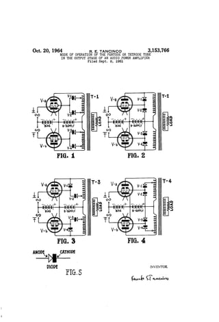
  • 2. UnitedStates Patent Office 3,153,766 Patented Oct. 20, 1964 3,553,766 MODE OF OSPERATION OF THE PENTO DE OR TETRODE TUBE IN THE OUTPUT STAGE OF AN AUDIO POWER AMPLEFER Renato E. Tancinco, Meycauayan, Bulacan, Philippines Fied Sept. 8, 1961, Ser. No. 36,817 Claims priority, application Philippines Sept. 2, 1960 5 Claims. (C. 330-22) This invention relates to a new concept in the mode of operation of a pentode or tetrode power tube in the output stage of an audio frequency amplifier. Up to the present stage of the art, the output tubes in an audio frequency amplifier operate only under one set of char acteristics which is determined by the mode of opera tion assigned to them. The following are the modes of operations under which a pentode or tetrode power tube may be made to operate: (1) Triode connected pentode or tetrode output stage. (2) Distributed load pentode or tetrode output stage or the so called "Uutra Linear Amplifiers.' (3) Straight pentode or tetrode output stage. (4) Unity coupled output stage. (5) “Extended Class A Amplifier” using a pair of triode connected push pull pentode or tetrode in parallel with another pair of the same type of tubes con nected as straight pentode or tetrode. The sixth mode of operation is offered by the under signed and is the subject of this patent application. In this new mode of operation, the output pentode or tetrode tube alternately operates between the two sets of characteristics assigned to them. These two sets of characteristics are determined by the position of the two taps on the plate winding of the output transformer to which the anodes of the back to back connected diodes, feeding the screen grid of the said power tube, are con nected. The particular set of characteristics under which the output tube operates is determined by the polarity of the grid signal voltage relative to the quiescent poten tial of the control grid, otherwise known as the grid bias. Some of the objectives of this invention are as follows: (1) To obtain high quality reproduction of sound with out the necessity of using expensive special output transformers or resorting to complex circuitry. (2) To be able to obtain the most power output avail able for a given power output tube and a given B supply voltage, commensurate with high plate circuit efficiency, low distortion, and low power consump tion during the absence of signal or during idling. (3) To attain the above objectives without the neces sity of using more than one pair of power output tubes or more than one power Supply or B-Supply. (4) To reduce the output impedance of the power out put stage before the application of any inverse feed back. (5) To be able to attain the above objectives without the need for very high signal grid drive voltage to the power output tubes. (6) To give the amplifier designer a free hand in the design of the whole amplifier. The said freedom is achieved by virute of the following: (a) Absence of inherent inverse feedback in the output stage. The manner of application of the inverse feedback is left entirely to the amplifier designer. (b) The designer is free to choose any type of pentode or tetrode power tube for the power amplifier stage. (c) The choice of the position of the taps on the plate winding of the output transformer is the 0. 5 20 25 30 35 40 45 50 55 60 65 70 2 privilege of the amplifier designer. The positions chosen will determine the two different sets of characteristics between which the power output tube will alternately operate. The New Circuit A good amplifier must not only be good in perform ance but it must meet the requirements of the manu facturer, the amplifier designer, and above all satisfy the ultimate user, i.e., the owner. it is a fact that in the reproduction of music, the high power peaks are relatively few and of very short durations, that, most of the time the amplifier may be considered as idling. Low consumption of power dur ing idling is therefore of paramount importance. An amplifier is usually rated at the maximum power that it can deliver during these peaks, with a minimum of dis tortion and good stability. The maximum power that a pair of power tubes can deliver is usually limited by the maximum plate dissipation rating of the said power tube. To get therefore the most out of a pair of power tubes, the plate circuit efficiency of output stage should be high. It is also very desirable to obtain high power outputs without the necessity of using very high signal grid drive voltages. In other words, the power sensi tivity of the output stage must be high. It is therefore clear that Class B operated pentode or tetrode power tubes appear to be ideal for the output stage. The re quirement of low distortion in output stages using the conventional Class B pentode or tetrode power tubes is, however, not easily met. The cause is the presence of a form of distortion, called the notch distortion, which occurs as a notch or fuzziness in the output signal wave form. In reality, this fuzziness in the output signal waveform is a form of shock excited self oscillation at some ultra-sonic frequency in the plate winding of the output transformer. The leakage inductance between the plate windings of the output transformer forms an oscillatory circuit in combination with the winding capacitance and other stray capacitances. This oscil latory circuit is shock excited into self-oscillation every time the plate current of the power tube is driven to cut off. Unfortunately the frequency of this fuzziness or notch distortion is so high that it is beyond the effec tive control of the inverse feedback loop that may be applied in the amplifier. Furthermore, the plate cur rent of the power tube which is the most logical part of the amplifier that can prevent the said distortion, has been driven to cut off. The said power tube, being then inactive, is therefore not in a position to prevent the occurrence of the said notch distortion. So far there are two successful solutions to the problem of prevent ing the occurrence of the notch distortion. They are exemplified in the Unity Coupled Amplifiers and the Extended Class A amplifiers. A third solution is offered by this invention, which is believed to be an entirely new concept in the mode of operation of pentode or tetrode power tubes in the output stage of an audio power amplifier. - The foregoing objectives will become more apparent from the following detailed description of various em bodiments of the invention and from the accompanying drawings wherein: FIG. 1 is an electrical schematic diagram illustrating a push-pull tetrode power amplifier incorporating the switching diodes in circuit between the screen grids and output transformer. FIGS. 2-4 are views similar to FIG. 1 but illustrating various modifications for connecting in the switching diodes; and FIG. 5 is a detail of one of the switching diodes in
  • 3. 3,153,766 d dicating the convention observed in designating its cath ode and anode components. Referring to FIG. 1 of the annexed drawing which forms a part of this patent application, there is shown a push pull tetrode power amplifier, which is operated as a conventional Class B output stage except for the man ner in which the screen grids of the power tetrodes V-a and V-b are fed. In a conventional output stage using Class B pentodes or tetrodes, the screen grids of the tubes are fed by the B-Supply for the plates or, if a different voltage is required for the screen grids, by a separate screen grid power supply. It will be noticed that the screen grids of the power tetrode tubes V-a and V-b are connected to the common cathodes of two pairs of back to back connected diodes, V-, V-2, V-3 and V-4. The anodes of the diodes V- and V-2 are connected respectively to taps No. 1 and No. 2 on the corresponding plate winding of the output transformer T-1 and similarly the diodes V-3 and W-4. When the tetrode V-a grid is driven to the positive direction by the signal, the plate swings to the negative direction relative to the B-Plus terminal of the B-Supply. Such a situation makes tap No. 2 on the plate winding more positive than the tap No. 1, causing diode V-1 to cut off -while diode V-2 remains conducting. Diode V-2 therefore, effectively ties the screen grid to tap No. 2 on the plate winding. Tube V-a will therefore behave in the same manner as when its screen grid is per manently connected to tap No. 2 of the plate winding of the output transformer. On the negative half of the signal wave, the grid of the power tetrode V-a is driven to the negative direction. The plate of the tube V-a then swings to the positive direction relative to the B Plus terminal of the B-Supply. Tap No. 1 therefore of the plate winding of the output transformer then becomes more positive than tap No. 2, thus causing diode V-2 to cut off and diode V-E to conduct instead. The conduction of diode V-1 effectively ties the screen grid of tube V-a to tap No. 1 in plate winding of the out put transformer T-1. Tube V-a then, will therefore be have as if its screen grid is permanently connected to tap No. 1 of the plate winding of the output transformer. In the absence of a signal, the two diodes V-1 and V-2 are both conducting and are sharing the screen grid cur rent drain of the tube V-a. It can be seen therefore that the characteristics of the power tetrode V-a during the positive half of the grid signal voltage is entirely different from those, during the negative half of the grid signal voltage. The tube V-a therefore automatically operates alternately between two different sets of char acteristics, with the aid of diodes V-1 and V-2. The polarity of the grid signal voltage determines under which set of characteristics the power tetrode V-a will operate. It must be noted however that the positions of taps No. 1 and No. 2 on the plate winding of V-a are identical respectively to those of the taps No. 4 and No. 3 on the plate winding of V-b. The proper positions of the taps on the plate windings are left to the discretion of the amplifier designer. They can be anywhere from the B-Plus terminal to the plate terminal of the plate windings. The limiting positions of the taps is shown in FIG. 2 of this drawing. Here, tap No. 1 is at the plate terminal of the plate winding of the output trans former while the tap No. 2 is at the B-Plus terminal of the B-Supply. In FIG. 2 of the drawing, power tetrode V-a operates as a straight tetrode on the positive halves of the grid signal voltage, while during the negative halves, it operates as a triode. On the positive half of the grid signal voltage, the screen grid of tube V-a is tied to the B-Plus terminal of the B-Supply while on the negative half of grid signal voltage, the screen grid is connected to its plate. Automatic Switching is ac complished by the back to back connected diodes V-1 and V-2. In this mode of operation, the output trans O 5 20 30 35 40 45 50 55 60 65 70 4. former T-2 can be any standard output transformer ordinarily available. Even though tube V-a is biased to the projected plate current cut off value like in con ventional Class B amplifiers, its plate current can never reach cut off. The action of the control grid in forcing a plate current cut off during the negative halves of the grid signal voltage, is effectively counteracted by the rise in the potential of the screen grid which is then tied to the plate due to the conduction of diode V-1. The low plate impedance of the then triode connected V-a effectively damps the plate winding connected to it, thus preventing the winding from ever being shock excited into self-oscillation. The possibility therefore, of the occurrence of notch distortion, can entirely be precluded. The fact, that the tube V-a is connected as a tetrode during the positive halves of the grid signal voltage, makes it possible to obtain a relatively large power output at high plate circuit efficiency and at very low power consumption during idling, like in the conventional Class B tetrode power amplifiers. We therefore have now an amplifier that performs very much like a conventional Class B tetrode amplifier with all its advantages but without its disadvantages, i.e., the notch distortion. It should be noted however, that the grid drive voltage requirements are low and are the same as when the output tubes are connected as in a conven tional Class B tetrode power amplifier. In the prototype amplifier that was tried by the under signed a pair of 807's were used for V-a and V-b and one pair of 6 x 4's were used in place of the diodes V-A, V-2, V-3 and V-4. The common cathodes of the 6 x 4's feed the screen grids of the 807's. The output transformer used was a “Merit' 55 watt P.A. output transformer with a plate to plate rated load of 3,300 ohms. The circuit used is shown on FIG. 2 of the draw ing. Although the output stage operates as a Class B tetrode power amplifier, the output impedance, without any inverse feed back is low and the same as that of a triode amplifier. This low output impedance is the re sult of the alternate Tetrode-Triode operation of the output tubes. FIG. 3 of the drawing shows a mode of operation in which the power output tubes operates as a distributed load tetrodes or "Ultra Linear' amplifier during the positive halves of the grid signal voltage and as triodes during the negative halves of the grid signal voltage. As in FIG. 2, the possibility of the occurrence of notch dis tortion in this case is non-existent. The circuit in FIG. 4 is the same as in FIG. 2 except that the anode of the diode V-1 is connected to the tap No. 1 on the plate winding of the output transformer T-4. In this case the positive voltage applied to the Screen grid of the tube V-a thru diode V-1 during the negative half of the grid signal voltage is just enough to prevent the plate current of the tetrode V-a from reaching the cut of point during the maximum power output ofthe amplifier. In the foregoing discussions, the principles involved in the operation of this new amplifier can be fully un derstood. In regards to the diodes V-1, V-2, V-3 and V-4, semi-conductor diodes may be used in lieu of thermionic diodes, provided however, that the peak in verse voltage of the diodes are not exceeded during the delivery of maximum power to the load or when the amplifier is unloaded while in operation. Advantages of This Invention The advantages that may be derived from the appli cation of this invention in the manufacture of high qual ity audio frequency power amplifiers may be summed up as follows: (1) The application of this invention may be con sidered the most practical approach to the design and manufacture of high quality reliable audio power am plifiers that are capable of relatively high power output
  • 4. 3,153,766 s with low distortion, high plate circuit efficiency, low power consumption during idling, and at a reasonably low cost. (2) The amplifier does not require specially designed output transformers. In fact, standard output trans formers commonly available can be successfully used. There is no need for sectionalized and intermeshed plate windings that are required for the successful operation of the conventional distributed load or "Ultra Linear” amplifiers, nor is it necessary to use a special, bi-filar wound output transformer as in the case of the unity coupled McIntosh and Gow amplifier. The presence of the full B-Supply voltage between the turns of this bi filar windings greatly affects the reliability of the whole amplifier. (3) The amplifier requires only one power supply and this power Supply is operated at signal ground po tential. The "Extended Class' A-2 amplifier requires an additional well regulated screen grid power supply for its successful operation. The "Circlotron Amplifier' of Electro Voice, Inc. requires two separate and identical power Supplies, one for each power output tube, and furthermore, these power supplies are operated above signal ground potential. The additional cost of the ex tra power Supply is worth considering, and moreover, operating the power supplies above signal ground poten tial can affect the frequency characteristics and the sta bilityofthe whole amplifier. (4) Only one pair of power output tubes are required for the successful operation of this amplifier. To equal the power output of a conventional amplifier using one pair of power output tubes, the "Extended Class A Am plifier' requires two pairs of power output tubes. Con sidering the present cost of good audio power output tubes, the additional cost of the extra pair of power tubes is certainly worth savings, (5) The output impedance of this amplifier before the application of any inverse feed back is low and the Same as that of a triode power amplifier. The alternate operation of the power output tubes as a triode or near triode during the negative halves of the grid signal volt age accounts for the low output impedance of this am plifier. (6) Elimination of the notch distortion is accomplished in this amplifier without resorting to Unity Coupling or Extended Class A operation with their attendant disad Vantages. (7) Compared to Unity Coupled amplifiers, the sig nal grid drive voltage requirement of this amplifier is very low. It is not necessary to design a special driver stage to deliver the high signal voltages at low distortion as is called for in the Unity Coupled amplifiers. It is very possible for the driver stage to contribute most of the distortion in the output of an otherwise distortion free Unity Coupled amplifier. Specially designed driver stages can increase the cost of an amplifier and add to the complexity of the circuit. (8) This amplifier is not very particular as to the type of the power output tube. The manufacturer or the am plifier designer is free to choose any power pentode or tetrodefor the outputstage of thisamplifier. (9) The absence of inherent inverse feedback in the output stage of this amplifier is a distinct advantage. The amplifier designer has therefore a free hand in the choice of the manner in which the inverse feedback may be applied. Inherent inverse feedback in the output stage is inevitable in Unity Coupled amplifiers. This inherent feedback accounts for the very high grid drive signal voltage requirements of Unity Coupled amplifiers. (10) The fact that the notch distortion is non-existent in the amplifier, makes it advantageous to set the grid bias of the power output tubes to the projected cut off value of the plate current. The amplifier is therefore capable of relatively high power output at high plate cir cuit efficiency, attendant to low power consumption dur ing idling. This will mean a very much longer life for 5 O 5 20 30 35 40 45 50 55 60 65 70 75 6 the power output tubes, less power consumption and sav ings in money for both the manufacturer and the end user. (11) The choice ofthe mode ofoperation of the power output tubes is entirely left to the discretion of the ampli fier. The desired two different sets of characteristics under which the power output tubes will alternately op erate may be obtained by the amplifier designer with the proper choice of the points in the plate windings of the output transformer to which the anodes of the back to back connected diodes are to be connected. The ampli fier designer is therefore completely free to choose the two different sets ofcharacteristics under which the power output tubes will alternately operate to obtain his desired results. (12) The circuitry of this amplifier is very simple. The simplicity of the circuitry makes it easy for the man ufacturer to duplicate the performance of the original model during the production run. Simplicity of the cir cuit contributes to the stability and reliability of the whole amplifier. In class B power amplifiers, the push pull output tubes alternate in the delivery of power to the load. The power output tubes deliver power to the load, only dur ing the positive half of the grid signal voltage. During the negative half of grid signal voltage, the plate current of the power tube is cut off. The power output tube is then inactive and therefore serving no useful purpose. The essence of this invention is to make the said inactive tube do some useful work, i.e., act as an effective damp ing element to the then inactive plate winding of the output transformer. During the negative halves of the grid signal voltage, the output tube is operated as a tri ode or near triode to prevent its plate current from ever reaching the cutoff point and to act as a low impedance shunt across the inactive plate winding of the output transformer. The action of this, otherwise inactive tube during the negative halves ofthe gridsignal voltage, effec tively prevents the occurrence of the notch distortion. I claim: 1. As an output stage for a push-pull audio amplifier the combination comprising first and second tubes con nected for push-pull anode loaded operation, each said tube including a cathode, anode, signal grid and a screen grid, a push-pull output transformer, said output trans former including first and second primaryportions respec tively connectedto and loading the anodes ofsaidfirstand Second tubes, first and second pairs of common-cathode back-to-back arranged diodes connected in shunt respec tively with said first and second primary portions of said Output transformer, and circuit means respectively con necting the common cathodes of said first and second pairs of diodes to the respective screen grids of said first and Second tubes foreffecting automatic switching ofeach said Screen grid alternately between the terminals of the corresponding primary portions of said output trans former. 2. A push-pull audio amplifier output stage as defined in claim 1 wherein said first and second portions of the primary of said output transformer are provided respec tively with first and second pairs of taps, and said first and second pairs of diodes are connected respectively to said pairs of taps for shunting the same to thereby effect said automatic Switching of each said screen grid alter nately between said taps. 3. A push-pull audio amplifier output stage as defined in claim 1 wherein said first and second pairs of diodes are connected respectively in shunt between the apper taining anode terminals and the positive terminal ofthe power Supply connected between the cathodes and a point on Said transformer primary intermediate the first and second portions thereof to thereby effect said automatic Switching of each said screen grid alternately between the apertaining anode terminal and said power Supply terminal. 4. A push-pull audio amplifier output stage as defined
  • 5. 3,153,766 7 in claim 1 wherein said first and second portions of the primary of said output transformer are each provided with a tap and said first and second pairs of diodes are connected respectively in shunt between the appertaining tap and the anode terminal of the appertaining tube to thereby effect said automatic switching ofeach said screen grid alternately between the corresponding tap and the anode terminal. 5. A push-pull audio amplifier output stage as defined in claim 1 wherein said first and second portions of the primary of said output transformer are each provided with a tap, and said first and second pairs of diodes are 0. 8 connected respectively in shunt between the appertaining tap and the positive terminal of the power supply con nected between the cathodes and a point on said trans former primary intermediate the first and second portions thereof to thereby effect said automatic switching of each said screen grid alternately between the corresponding tap and said power supply terminal. References Cited in the file of this patent UNITEd STATES PATENTS Hafler et al. ------------- June 7, 1955 Gabor et al. ------------- Jan. 13, 1959 2,710,312 2,868,896