30 sems and measure of the total elastic envelope (ee)
•Download as DOCX, PDF•
0 likes•93 views

SEMS and MEASURE of the TOTAL ELASTIC ENVELOPE (EE) In the next Fig. 1 we suppose the white curve AB is the structural axis of a wing which represents its elastic envelope (EE). The lines AC and BC represent the tangents of the rotation angles of points A and B.

Recommended
More Related Content
What's hot
What's hot (20)
Similar to 30 sems and measure of the total elastic envelope (ee)
Similar to 30 sems and measure of the total elastic envelope (ee) (20)
More from Miguel Cabral Martín
More from Miguel Cabral Martín (20)
Recently uploaded
Recently uploaded (20)
30 sems and measure of the total elastic envelope (ee)
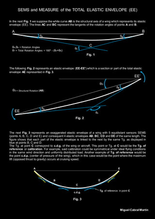
- 1. SEMS and MEASURE of the TOTAL ELASTIC ENVELOPE (EE) In the next Fig. 1 we suppose the white curve AB is the structural axis of a wing which represents its elastic envelope (EE). The lines AC and BC represent the tangents of the rotation angles of points A and B. The following Fig. 2 represents an elastic envelope (EE-EE') which is a section or part of the total elastic envelope AE represented in Fig. 3. The next Fig. 3 represents an exaggerated elastic envelope of a wing with 5 equidistant sensors SEMS (points A, B, C, D and E) and consequent 4 elastic envelopes AB, BC, CD and DE of the same length. The figure shows that each part of the elastic envelope is linked to the next by the same Tg. as displayed in blue at points B, C and D. The Tg. at point C correspond to c.d.g. of the wing or aircraft. This point or Tg. at C would be the Tg. of reference or calibration. For example, said calibration could be symmetrical under ideal flying conditions in the same wind direction and uniformly distributed load. Another example of Tg. of reference would be the point c.d.p. (center of pressure of the wing), which in this case would be the point where the maximum lift (opposed thrust to gravity) occurs at cruising speed. C A B θA θB θA,θB = Rotation Angles θT = Total Rotation Angles = 180º - (θA+θB) θT Fig. 1 Fig. 3 c.d.g. Tg. of reference in point C B C D EA θS EE EE’ θA θB θS = Structural Rotation (AB) θT Fig. 2 Miguel Cabral Martín