SlideShare a Scribd company logo
1 of 5
Download to read offline
P700 SERIES
 ENGINEERING DATA SHEET                                                SOLID STATE POWER CONTROLLER
                                                                           28 VDC, 1PNO, 150 AMP RATING

                                                      DESCRIPTION

                                                      The P700 Solid State Power Controller (SSPC) is a fully rated 150 Amperes device
                                                      available for use in today's and tomorrow's Power Systems.

                                                      This LEACH SSPC features reliable trouble free switching together with real short circuit
                                                      protection. Load current is sensed and shutdown initiated within microseconds. Two
                                                      status signals, derived from the load current value and from the device gate, are
                                                      reported via optical isolators.

                                                      Employing a Power FET output stage, and by using thick film technology, this device
                                                      offers low power dissipation, high off state impedance, low on state resistance and low
                                                      on state voltage drop. Designed to operate in 28 VDC systems, this device does not
                                                      require derating for any load type. These features, together with this high reliability,
                                                      make it ideal for Power System applications.
                    SIZE: 96 x 80 x 38 mm
                   WEIGHT: MAX 500 GMS                This device is also available in 75 Amperes and 220 Amperes.
FEATURES
 . Power FET output                                                   . Trip indicator
 . Low voltage drop                                                   . Optically isolated (500 Vrms)
 . Built-in overload and short circuit protection                     . High MTBF
 . Trip-free characteristics                                          . Full rated current up to 90° C
 . Load status indictor                                               . Fast response
BLOCK DIAGRAM


 LEACH ® INTERNATIONAL
                                                    North America                  Europe, SA                  Asia-Pacific Ltd.
                                                    6900 Orangethorpe Ave.         2 Rue Goethe                20/F Shing Hing Commercial Bldg.
 Solutions for Power Switching and Control          P.O. Box 5032                  57430 Sarralbe              21-27 Wing Kut Street
                                                    Buena Park, CA 90622 USA       France                      Central, Hong Kong
 www.leachintl.com                                  Tel: (01) 714-736-7599         Tel: (33) 3 87 97 98 97     Tel: (852) 2 191 2886
                                                    Fax: (01) 714-670-1145         Fax: (33) 3 87 97 84 04     Fax: (852) 2 389 5803

Date of issue: 11/01                                               - 42 -                                                              Page 1 of 5
ELECTRICAL CHARACTERISTICS                                                                               P700 SERIES
 INPUT PARAMETERS
 Parameter                                                            Symol.     Min.   Max.        Unit          Note

 Control Power (On)                                                   VIHC       16.0   33.5         V

 Control Power (Off)                                                   VILC       0      5           V

 Control GND Current (On)                                             VIHC              20           mA

 Control Power (Trip) Current                                         ITRIP             11           A             1

 Control Minimum Voltage (On)                                          VILS       0     17           V             2

 Control Minimum Voltage (Off)                                         IIHS       23    33.5         V             2

 Control Minimum Voltage Current                                       VIHS             0.5          mA

 Control Open (On)                                                    RIHS        15                 kΩ

 Control Open (Off)                                                    RILS              5           kΩ

 Control Open Current                                                  IILS      0.5                 mA

 Control Open Blocking Voltage                                         VB         15                 V             3

 RCCBIN (On)                                                          RIHR               5           kΩ

 RCCBIN (Off)                                                          RILR       15                 kΩ

 RCCBIN Current                                                        IILR             15           mA

 RCCBIN Blocking voltage                                               VBR       33.5                V             3
Notes:
1. When RCCB is being driven ITRIP = 11 A max.
2. Control Minimum Voltage has a hysteresis of 1 V min.
3. Driver must be able to withstand this voltage.

INPUT SIGNAL TRUTH TABLE
               RCCBIN                    CONTROL          CONT.MIN.            CONT.             Solid State
               Control                    POWER           VOLTAGE              OPEN            Power Controller
    1            OPEN                       0V              < 17 V             GND                  OPEN
    2            OPEN                       0V              < 17 V             OPEN                 OPEN
    3            OPEN                       0V              > 23 V             GND                  OPEN
    4            OPEN                       0V              > 23 V             OPEN                 OPEN
    5            OPEN                      28 V             < 17 V             GND                  OPEN
    6            OPEN                      28 V             < 17 V             OPEN                 OPEN
    7            OPEN                      28 V             > 23 V             GND                  OPEN
    8            OPEN                      28 V             > 23 V             OPEN                 OPEN
    9            GND                        0V              < 17 V             GND                  OPEN
   10            GND                        0V              < 17 V             OPEN                 OPEN
   11            GND                        0V              > 23 V             GND                  OPEN
   12            GND                        0V              > 23 V             OPEN                 OPEN
   13            GND                       28 V             < 17 V             GND                  OPEN
   14            GND                       28 V             < 17 V             OPEN               CLOSED 1
   15            GND                       28 V             > 23 V             GND                  OPEN
   16            GND                       28 V             > 23 V             OPEN                 OPEN
Notes :
1. SSPC will be closed if not tripped.


Date of issue: 11/01                                        - 43 -                                           Page 2 of 5
ELECTRICAL CHARACTERISTICS                                                                                                   P700 SERIES
OUTPUT PARAMETERS
Parameter                                                                          Symbol          Min.        Max.        Unit
Load current                                                                          IL             0          150          A              1, 8
On State Voltage Drop                                                                VLD                        300         mV               2
Off State Line Voltage                                                                VL                       33.5          V               3
Leakage Current                                                                      ILL                        20          mA               4
Trip Current                                                                          IT            104         120         %                5
Gate Status High Impedance                                                          ROHS             1                     MΩ                7
Gate Status Low Impedance                                                           ROLS                        1.5         kΩ               7
Load Status High Impedance                                                          ROHS             1                     MΩ                7
Load Status Low Impedance                                                           ROLL                        1.5         kΩ               7
Load Status Pickup                                                                   ISON                       15        % Irated
Load Status Dropout                                                                 ISOFF            5                    % Irated
RCCBOUT Voltage High                                                                               33.5         V
RCCBOUT Impedance                                                                                    2           4           Ω
RCCBOUT Status Low Impedance                                                        ROSLS                       1.5         kΩ               7
RCCBOUT Status High Impedance                                                      ROSHS             1                     MΩ                7
Notes:
1. Load current is subject to thermal derating.
2. Load current is 100% rated current.
3. Reverse polarity is not blocked and may damage the SSPC.
4. At VL = 28 °C, case temperature = 70° C.
5. Refer to trip characteristics.
6. RCCBOUT current sourced on device trip, compatible with 0,5 Amp circuit breaker type MS 22073.
7. Open collector type output. Maximum blocking voltage is 75V.
8. 150 A is 100% rated load, for the existing device. Variants 75 amps and 220 amps are also available.
TIMING DIAGRAM


STATUS CONDITIONS
   State       Control          Gate-Status             Load-Status             RCCBOUT                  RCCBOUT-Status              Condition
     1           Off               Low                     Low                    Low                        High                      Error
     2           Off               Low                     High                   Low                        High                      Error
     3           Off               High                    Low                    Low                        High                      Error
     4           Off               High                    High                   Low                        High                    Normal Off
     5           On                Low                     Low                    Low                        High                    Normal On
     6           On                Low                     High                   Low                        High                     No load
     7           On                High                    Low                    Low                        High                      Error
     8           On                High                    High                   High                       Low                      Tripped


Date of issue: 11/01                                                   - 44 -                                                          Page 3 of 5
EMC CHARACTERISTICS                                                                                                       P700 SERIES

 The device will meet the following EMC-requirements

 - Magnetic effect                                per DO-160C, section 15,                      category     A
 - Power inputs                                   per DO-160C, section 16,                      category     A
 - Voltage spike                                  per DO-160C, section 17,                      category     A
 - Audio Frequency Conducted Susceptibility       per DO-160C, section 18,                      category     Z
 - Induced signal Susceptibility                  per DO-160C, section 19,                      category     A
 - Radio Frequency Susceptibility,                per DO-160C, section 20,                      category     W
                                   HIRF: 10 KHz - 400 MHz: 100 V/m
                                         400 MHz - 18 GHz: 150 V/m
 - Emission of Radio Frequency Energy             per DO-160C, section 21,                      category Z
 - Lightening, PIN injection                      per DO-160C, section 22,
                                                          VOC       ICs
                                   wave form 2            300        60
                                             3 (1 MHz)    600        24
                                             4            300        60


ENVIRONMENTAL CHARACTERISTICS
 Parameter                              Symbol                                Min.                                Max.      Unit      Note

 Operational temp. range                 Case                                  -40                                +90       °C          1

 Storage temp. range                                                           -55                                +85       °C          1

 Altitude                                                                     -1300                              +51000      ft         2

 Vibration                            per DO-160C, Section 8, Cat. C

 Acceleration                         per MIL-STD-810E, Method 513A, Cat. aircraft

 Shock                                per DO-160C, Section 7

 Seal (internal modules)              per MIL-STD-883, Method 1014, Condition A2, 5 x 10⁻⁶ atm cc/sec air.

PHYSICAL DATA (mm)
Case Finish: Plastic. Base: Aluminum. Finish: Flat: Black. Mass: 500 grams max.
Part Numbers: P700-A753-E002 75 Amp device. P700-A154-E002 150 Amp device. P700-A224-E002 220 Amp device


This engineering data sheet is designed for initial selection and comparison of products. While every effort is made to ensure the accuracy
of all data, each part number, and its application, must be controlled by a Product Control Drawing (PCD). Please contact PowerCom, a
Leach International Company, for further information.


Date of issue: 11/01                                                - 45 -                                                        Page 4 of 5
TIMING                                                                                                     P700 SERIES
 Parameter                                                                Symbol      Typ.   Max.   Unit       Notes

 STATUS Rise and Fall Time                                                     t0             20    µs          1

 Turn-on                                                                       t1            5000   µs          1

 Load Current Rise Time                                                        t2            1000   µs          1

 Turn off                                                                      t3            5000   µs          1

 Load Current Fall Time                                                        t4            1000   µs         1, 2

 BIT/TRIP Rise and Fall Time                                                   t5             20    µs          1

 RCCBOOT Status                                                                t6            600    µs          1
Notes:
1. All timing measurements taken at 10% and 90% points with a resistive rated load.
2. Load current fall time from trip event is dependant on overload condition.

TRIP CHARACTERISTIC


THERMAL DERATING


Date of issue: 11/01                                                  - 46 -                                  Page 5 of 5

More Related Content

What's hot

Gs jd-200
Gs jd-200Gs jd-200
Gs jd-200jlbn24
 
ANAVIEW's Smallest Class D OEM Amplifier Board
ANAVIEW's Smallest Class D OEM Amplifier BoardANAVIEW's Smallest Class D OEM Amplifier Board
ANAVIEW's Smallest Class D OEM Amplifier BoardHTCS LLC
 
DS-00593-14-XTR70020-High-temperature, High Input Voltage, 2A Positive LDO Re...
DS-00593-14-XTR70020-High-temperature, High Input Voltage, 2A Positive LDO Re...DS-00593-14-XTR70020-High-temperature, High Input Voltage, 2A Positive LDO Re...
DS-00593-14-XTR70020-High-temperature, High Input Voltage, 2A Positive LDO Re...Benjamin Parpillon
 
IL4116 -Datasheet - VISHAY
IL4116 -Datasheet - VISHAYIL4116 -Datasheet - VISHAY
IL4116 -Datasheet - VISHAYMarioFarias18
 
BlueOptics Bo86jxx240d 10gbase-cwdm xenpak transceiver 1471nm-1611nm 40 kilo...
BlueOptics Bo86jxx240d 10gbase-cwdm xenpak transceiver 1471nm-1611nm  40 kilo...BlueOptics Bo86jxx240d 10gbase-cwdm xenpak transceiver 1471nm-1611nm  40 kilo...
BlueOptics Bo86jxx240d 10gbase-cwdm xenpak transceiver 1471nm-1611nm 40 kilo...CBO GmbH
 
MUSES8920の英語のデータシート
MUSES8920の英語のデータシートMUSES8920の英語のデータシート
MUSES8920の英語のデータシートspicepark
 
BlueOptics Bo86jxx210d 10gbase-cwdm xenpak transceiver 1271nm-1451nm 10km sin...
BlueOptics Bo86jxx210d 10gbase-cwdm xenpak transceiver 1271nm-1451nm 10km sin...BlueOptics Bo86jxx210d 10gbase-cwdm xenpak transceiver 1271nm-1451nm 10km sin...
BlueOptics Bo86jxx210d 10gbase-cwdm xenpak transceiver 1271nm-1451nm 10km sin...CBO GmbH
 
K39 Controller
K39 ControllerK39 Controller
K39 ControllerJoseph
 
BlueOptics Bo86jxx280d 10gbase-cwdm xenpak transceiver 1471nm-1611nm 80 kilo...
BlueOptics Bo86jxx280d 10gbase-cwdm xenpak transceiver 1471nm-1611nm  80 kilo...BlueOptics Bo86jxx280d 10gbase-cwdm xenpak transceiver 1471nm-1611nm  80 kilo...
BlueOptics Bo86jxx280d 10gbase-cwdm xenpak transceiver 1471nm-1611nm 80 kilo...CBO GmbH
 
312742 ds
312742 ds312742 ds
312742 ds____
 
XLSEMI XL140 2A 380KHz 18V Buck DC to DC Converter
XLSEMI XL140 2A 380KHz 18V Buck DC to DC ConverterXLSEMI XL140 2A 380KHz 18V Buck DC to DC Converter
XLSEMI XL140 2A 380KHz 18V Buck DC to DC Converterdegarden
 

What's hot (20)

Gs jd-200
Gs jd-200Gs jd-200
Gs jd-200
 
ANAVIEW's Smallest Class D OEM Amplifier Board
ANAVIEW's Smallest Class D OEM Amplifier BoardANAVIEW's Smallest Class D OEM Amplifier Board
ANAVIEW's Smallest Class D OEM Amplifier Board
 
Tda8511 j
Tda8511 jTda8511 j
Tda8511 j
 
Acs712 datasheet
Acs712 datasheetAcs712 datasheet
Acs712 datasheet
 
DS-00593-14-XTR70020-High-temperature, High Input Voltage, 2A Positive LDO Re...
DS-00593-14-XTR70020-High-temperature, High Input Voltage, 2A Positive LDO Re...DS-00593-14-XTR70020-High-temperature, High Input Voltage, 2A Positive LDO Re...
DS-00593-14-XTR70020-High-temperature, High Input Voltage, 2A Positive LDO Re...
 
Pdiusbd11
Pdiusbd11Pdiusbd11
Pdiusbd11
 
Acs712
Acs712Acs712
Acs712
 
IL4116 -Datasheet - VISHAY
IL4116 -Datasheet - VISHAYIL4116 -Datasheet - VISHAY
IL4116 -Datasheet - VISHAY
 
BlueOptics Bo86jxx240d 10gbase-cwdm xenpak transceiver 1471nm-1611nm 40 kilo...
BlueOptics Bo86jxx240d 10gbase-cwdm xenpak transceiver 1471nm-1611nm  40 kilo...BlueOptics Bo86jxx240d 10gbase-cwdm xenpak transceiver 1471nm-1611nm  40 kilo...
BlueOptics Bo86jxx240d 10gbase-cwdm xenpak transceiver 1471nm-1611nm 40 kilo...
 
RT7257E Datasheet PDF
RT7257E Datasheet PDFRT7257E Datasheet PDF
RT7257E Datasheet PDF
 
MUSES8920の英語のデータシート
MUSES8920の英語のデータシートMUSES8920の英語のデータシート
MUSES8920の英語のデータシート
 
BlueOptics Bo86jxx210d 10gbase-cwdm xenpak transceiver 1271nm-1451nm 10km sin...
BlueOptics Bo86jxx210d 10gbase-cwdm xenpak transceiver 1271nm-1451nm 10km sin...BlueOptics Bo86jxx210d 10gbase-cwdm xenpak transceiver 1271nm-1451nm 10km sin...
BlueOptics Bo86jxx210d 10gbase-cwdm xenpak transceiver 1271nm-1451nm 10km sin...
 
Datasheet (4)
Datasheet (4)Datasheet (4)
Datasheet (4)
 
74 Lcx08
74 Lcx0874 Lcx08
74 Lcx08
 
K39 Controller
K39 ControllerK39 Controller
K39 Controller
 
Pt4115 e
Pt4115 ePt4115 e
Pt4115 e
 
BlueOptics Bo86jxx280d 10gbase-cwdm xenpak transceiver 1471nm-1611nm 80 kilo...
BlueOptics Bo86jxx280d 10gbase-cwdm xenpak transceiver 1471nm-1611nm  80 kilo...BlueOptics Bo86jxx280d 10gbase-cwdm xenpak transceiver 1471nm-1611nm  80 kilo...
BlueOptics Bo86jxx280d 10gbase-cwdm xenpak transceiver 1471nm-1611nm 80 kilo...
 
312742 ds
312742 ds312742 ds
312742 ds
 
XLSEMI XL140 2A 380KHz 18V Buck DC to DC Converter
XLSEMI XL140 2A 380KHz 18V Buck DC to DC ConverterXLSEMI XL140 2A 380KHz 18V Buck DC to DC Converter
XLSEMI XL140 2A 380KHz 18V Buck DC to DC Converter
 
Al5809
Al5809Al5809
Al5809
 

Similar to P700; 75-150A Programmable Power Controller

Similar to P700; 75-150A Programmable Power Controller (20)

Lpc662
Lpc662Lpc662
Lpc662
 
Webinar: Desmistificando projetos de fontes chaveadas
Webinar: Desmistificando projetos de fontes chaveadasWebinar: Desmistificando projetos de fontes chaveadas
Webinar: Desmistificando projetos de fontes chaveadas
 
LM2575 Voltage Regulator Datasheet
LM2575 Voltage Regulator DatasheetLM2575 Voltage Regulator Datasheet
LM2575 Voltage Regulator Datasheet
 
Ne555
Ne555Ne555
Ne555
 
Datasheet 555
Datasheet 555Datasheet 555
Datasheet 555
 
Mp8126 r1.03 1384507
Mp8126 r1.03 1384507Mp8126 r1.03 1384507
Mp8126 r1.03 1384507
 
WEBINAR - VIPer Plus
WEBINAR - VIPer PlusWEBINAR - VIPer Plus
WEBINAR - VIPer Plus
 
tca785
tca785tca785
tca785
 
Original Power Supply IC MIP2C2 2C2 DIP-7 New
Original Power Supply IC MIP2C2 2C2 DIP-7 NewOriginal Power Supply IC MIP2C2 2C2 DIP-7 New
Original Power Supply IC MIP2C2 2C2 DIP-7 New
 
Adi jul1311
Adi jul1311Adi jul1311
Adi jul1311
 
Datasheet
DatasheetDatasheet
Datasheet
 
Datasheet
DatasheetDatasheet
Datasheet
 
pe lab manual
pe lab manualpe lab manual
pe lab manual
 
Datasheet
DatasheetDatasheet
Datasheet
 
Lm567
Lm567Lm567
Lm567
 
Ed ch 9 power
Ed ch 9 powerEd ch 9 power
Ed ch 9 power
 
MCP656x High Speed Low Power Comparators
MCP656x High Speed Low Power ComparatorsMCP656x High Speed Low Power Comparators
MCP656x High Speed Low Power Comparators
 
Master thesis presentation
Master thesis presentationMaster thesis presentation
Master thesis presentation
 
Ad598
Ad598Ad598
Ad598
 
Original High Performance Off-Line Controller IC ACT30 CT30 30 New Active-Semi
Original High Performance Off-Line Controller IC ACT30 CT30 30 New Active-SemiOriginal High Performance Off-Line Controller IC ACT30 CT30 30 New Active-Semi
Original High Performance Off-Line Controller IC ACT30 CT30 30 New Active-Semi
 

P700; 75-150A Programmable Power Controller

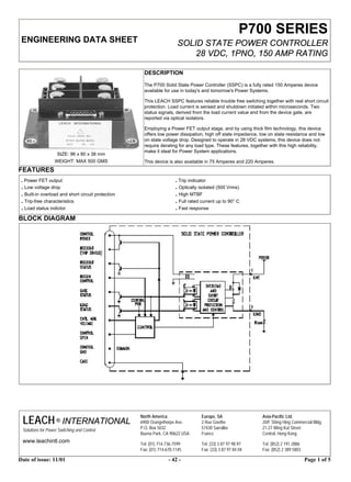
  • 1. P700 SERIES ENGINEERING DATA SHEET SOLID STATE POWER CONTROLLER 28 VDC, 1PNO, 150 AMP RATING DESCRIPTION The P700 Solid State Power Controller (SSPC) is a fully rated 150 Amperes device available for use in today's and tomorrow's Power Systems. This LEACH SSPC features reliable trouble free switching together with real short circuit protection. Load current is sensed and shutdown initiated within microseconds. Two status signals, derived from the load current value and from the device gate, are reported via optical isolators. Employing a Power FET output stage, and by using thick film technology, this device offers low power dissipation, high off state impedance, low on state resistance and low on state voltage drop. Designed to operate in 28 VDC systems, this device does not require derating for any load type. These features, together with this high reliability, make it ideal for Power System applications. SIZE: 96 x 80 x 38 mm WEIGHT: MAX 500 GMS This device is also available in 75 Amperes and 220 Amperes. FEATURES . Power FET output . Trip indicator . Low voltage drop . Optically isolated (500 Vrms) . Built-in overload and short circuit protection . High MTBF . Trip-free characteristics . Full rated current up to 90° C . Load status indictor . Fast response BLOCK DIAGRAM LEACH ® INTERNATIONAL North America Europe, SA Asia-Pacific Ltd. 6900 Orangethorpe Ave. 2 Rue Goethe 20/F Shing Hing Commercial Bldg. Solutions for Power Switching and Control P.O. Box 5032 57430 Sarralbe 21-27 Wing Kut Street Buena Park, CA 90622 USA France Central, Hong Kong www.leachintl.com Tel: (01) 714-736-7599 Tel: (33) 3 87 97 98 97 Tel: (852) 2 191 2886 Fax: (01) 714-670-1145 Fax: (33) 3 87 97 84 04 Fax: (852) 2 389 5803 Date of issue: 11/01 - 42 - Page 1 of 5
  • 2. ELECTRICAL CHARACTERISTICS P700 SERIES INPUT PARAMETERS Parameter Symol. Min. Max. Unit Note Control Power (On) VIHC 16.0 33.5 V Control Power (Off) VILC 0 5 V Control GND Current (On) VIHC 20 mA Control Power (Trip) Current ITRIP 11 A 1 Control Minimum Voltage (On) VILS 0 17 V 2 Control Minimum Voltage (Off) IIHS 23 33.5 V 2 Control Minimum Voltage Current VIHS 0.5 mA Control Open (On) RIHS 15 kΩ Control Open (Off) RILS 5 kΩ Control Open Current IILS 0.5 mA Control Open Blocking Voltage VB 15 V 3 RCCBIN (On) RIHR 5 kΩ RCCBIN (Off) RILR 15 kΩ RCCBIN Current IILR 15 mA RCCBIN Blocking voltage VBR 33.5 V 3 Notes: 1. When RCCB is being driven ITRIP = 11 A max. 2. Control Minimum Voltage has a hysteresis of 1 V min. 3. Driver must be able to withstand this voltage. INPUT SIGNAL TRUTH TABLE RCCBIN CONTROL CONT.MIN. CONT. Solid State Control POWER VOLTAGE OPEN Power Controller 1 OPEN 0V < 17 V GND OPEN 2 OPEN 0V < 17 V OPEN OPEN 3 OPEN 0V > 23 V GND OPEN 4 OPEN 0V > 23 V OPEN OPEN 5 OPEN 28 V < 17 V GND OPEN 6 OPEN 28 V < 17 V OPEN OPEN 7 OPEN 28 V > 23 V GND OPEN 8 OPEN 28 V > 23 V OPEN OPEN 9 GND 0V < 17 V GND OPEN 10 GND 0V < 17 V OPEN OPEN 11 GND 0V > 23 V GND OPEN 12 GND 0V > 23 V OPEN OPEN 13 GND 28 V < 17 V GND OPEN 14 GND 28 V < 17 V OPEN CLOSED 1 15 GND 28 V > 23 V GND OPEN 16 GND 28 V > 23 V OPEN OPEN Notes : 1. SSPC will be closed if not tripped. Date of issue: 11/01 - 43 - Page 2 of 5
  • 3. ELECTRICAL CHARACTERISTICS P700 SERIES OUTPUT PARAMETERS Parameter Symbol Min. Max. Unit Load current IL 0 150 A 1, 8 On State Voltage Drop VLD 300 mV 2 Off State Line Voltage VL 33.5 V 3 Leakage Current ILL 20 mA 4 Trip Current IT 104 120 % 5 Gate Status High Impedance ROHS 1 MΩ 7 Gate Status Low Impedance ROLS 1.5 kΩ 7 Load Status High Impedance ROHS 1 MΩ 7 Load Status Low Impedance ROLL 1.5 kΩ 7 Load Status Pickup ISON 15 % Irated Load Status Dropout ISOFF 5 % Irated RCCBOUT Voltage High 33.5 V RCCBOUT Impedance 2 4 Ω RCCBOUT Status Low Impedance ROSLS 1.5 kΩ 7 RCCBOUT Status High Impedance ROSHS 1 MΩ 7 Notes: 1. Load current is subject to thermal derating. 2. Load current is 100% rated current. 3. Reverse polarity is not blocked and may damage the SSPC. 4. At VL = 28 °C, case temperature = 70° C. 5. Refer to trip characteristics. 6. RCCBOUT current sourced on device trip, compatible with 0,5 Amp circuit breaker type MS 22073. 7. Open collector type output. Maximum blocking voltage is 75V. 8. 150 A is 100% rated load, for the existing device. Variants 75 amps and 220 amps are also available. TIMING DIAGRAM STATUS CONDITIONS State Control Gate-Status Load-Status RCCBOUT RCCBOUT-Status Condition 1 Off Low Low Low High Error 2 Off Low High Low High Error 3 Off High Low Low High Error 4 Off High High Low High Normal Off 5 On Low Low Low High Normal On 6 On Low High Low High No load 7 On High Low Low High Error 8 On High High High Low Tripped Date of issue: 11/01 - 44 - Page 3 of 5
  • 4. EMC CHARACTERISTICS P700 SERIES The device will meet the following EMC-requirements - Magnetic effect per DO-160C, section 15, category A - Power inputs per DO-160C, section 16, category A - Voltage spike per DO-160C, section 17, category A - Audio Frequency Conducted Susceptibility per DO-160C, section 18, category Z - Induced signal Susceptibility per DO-160C, section 19, category A - Radio Frequency Susceptibility, per DO-160C, section 20, category W HIRF: 10 KHz - 400 MHz: 100 V/m 400 MHz - 18 GHz: 150 V/m - Emission of Radio Frequency Energy per DO-160C, section 21, category Z - Lightening, PIN injection per DO-160C, section 22, VOC ICs wave form 2 300 60 3 (1 MHz) 600 24 4 300 60 ENVIRONMENTAL CHARACTERISTICS Parameter Symbol Min. Max. Unit Note Operational temp. range Case -40 +90 °C 1 Storage temp. range -55 +85 °C 1 Altitude -1300 +51000 ft 2 Vibration per DO-160C, Section 8, Cat. C Acceleration per MIL-STD-810E, Method 513A, Cat. aircraft Shock per DO-160C, Section 7 Seal (internal modules) per MIL-STD-883, Method 1014, Condition A2, 5 x 10⁻⁶ atm cc/sec air. PHYSICAL DATA (mm) Case Finish: Plastic. Base: Aluminum. Finish: Flat: Black. Mass: 500 grams max. Part Numbers: P700-A753-E002 75 Amp device. P700-A154-E002 150 Amp device. P700-A224-E002 220 Amp device This engineering data sheet is designed for initial selection and comparison of products. While every effort is made to ensure the accuracy of all data, each part number, and its application, must be controlled by a Product Control Drawing (PCD). Please contact PowerCom, a Leach International Company, for further information. Date of issue: 11/01 - 45 - Page 4 of 5
  • 5. TIMING P700 SERIES Parameter Symbol Typ. Max. Unit Notes STATUS Rise and Fall Time t0 20 µs 1 Turn-on t1 5000 µs 1 Load Current Rise Time t2 1000 µs 1 Turn off t3 5000 µs 1 Load Current Fall Time t4 1000 µs 1, 2 BIT/TRIP Rise and Fall Time t5 20 µs 1 RCCBOOT Status t6 600 µs 1 Notes: 1. All timing measurements taken at 10% and 90% points with a resistive rated load. 2. Load current fall time from trip event is dependant on overload condition. TRIP CHARACTERISTIC THERMAL DERATING Date of issue: 11/01 - 46 - Page 5 of 5