
Recommended
Recommended
More Related Content
Viewers also liked
Similar to Refrigeration fundamental
Similar to Refrigeration fundamental (20)
Recently uploaded
Recently uploaded (20)
Refrigeration fundamental
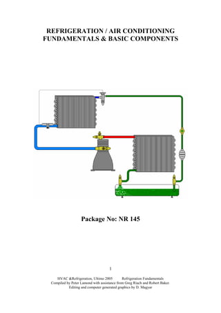
- 1. REFRIGERATION / AIR CONDITIONING FUNDAMENTALS & BASIC COMPONENTS Package No: NR 145 HVAC &Refrigeration, Ultimo 2005 Refrigeration Fundamentals Compiled by Peter Lamond with assistance from Greg Riach and Robert Baker. Editing and computer generated graphics by D. Magyar 1
- 2. HVAC &Refrigeration, Ultimo 2005 Refrigeration Fundamentals Compiled by Peter Lamond with assistance from Greg Riach and Robert Baker. Editing and computer generated graphics by D. Magyar 2 REFRIGERATION / AIR CONDITIONING FUNDAMENTALS & BASIC COMPONENTS Package No: NR 145 Nominal Student Hours: Flexible. Delivery: Competence in this training program can be achieved through either a formal education setting or in the workplace environment. Recognition of Prior Learning: The student / candidate may be granted recognition of prior learning if the evidence presented is authentic and valid and covers the content as laid out in this package. Package Purpose: In this program students will study the Principles of Refrigeration as applied to the vapour compression cycle. Identify, list and describe the function and operation of the Major Components and Flow Controls as utilised in the Vapour Compression System. Additionally, students are introduced to the basic Fundamentals of Air Conditioning and associated processes. Suggested Resources: Boyle G., Australian Refrigeration and Air Conditioning (ARAC) Volumes 1 & 2, 4th edition, WestOne Services. Assessment Strategy: The assessment of this package is holistic in nature and requires the demonstration of the knowledge and skills identified in the package content. To be successful in this package the student must show evidence of achievement in accordance with the package purpose.
- 3. HVAC &Refrigeration, Ultimo 2005 Refrigeration Fundamentals Compiled by Peter Lamond with assistance from Greg Riach and Robert Baker. Editing and computer generated graphics by D. Magyar 3 Additional Resources: Althouse A. D., Turnquist C. H., Bracciano A.F., Modern Refrigeration and Air Conditioning, 18th Edition, The Goodheart-Willcox Company Inc Dossat Roy J., Horan Thomas J., Principles of Refrigeration, Fifth Edition, Prentice Hall Trott A. R., Welch T. C., Refrigeration & Air Conditioning, Third Edition, Butterworth Heinemann Whitman W. C., Johnson W. M., Tomczyk J. A., Refrigeration and Air Conditioning Technology 5th Edition, Thomson Delmar Learning Refrigeration and Air Conditioning, 3rd Edition; Air Conditioning and Refrigeration Institute. Library Reference 621.56REFR Videos: History of Refrigeration; TAFE SA Cat No 88.017 9 mins (SIT No. 92) Jobs in Air Conditioning; AMCA 11 min 29 sec (SIT No 67) History of the Refrigerator (SIT No 75) Heat & Pressure; TAFE SA Cat No 85.022 16 mins (SIT No A1) Basic Refrigeration Cycle; TAFE SA Cat No 85.050 9 mins (SIT No A2) Reciprocating Compressors: TAFE SA Cat No 86.040 7 mins (SIT NoG1)
- 4. HVAC &Refrigeration, Ultimo 2005 Refrigeration Fundamentals Compiled by Peter Lamond with assistance from Greg Riach and Robert Baker. Editing and computer generated graphics by D. Magyar 4 Content Summary: Refrigeration Fundamentals: 1. History of Refrigeration. 6 2. Six Main Classifications of the Industry. 10 Assignment. 12 3. Matter. 13 4. Heat and Temperature. 16 5. Sensible and Latent Heat. 22 Product Storage Data. 24 Heat Load Calculations. 25 6. Pressure. 29 7. Refrigerant Conditions. 34 8. Refrigerant Relationship. 38 Pressure Temperature Charts.(Saturation Charts). 40 Practical Exercise 1. 41 9. Introduction to the Basic Vapour Compression System. 43 10. Major Components of the Vapour Compression System. Compressors. 47 Condensers. 53 Evaporators. 59 Temperature Difference of the Condenser and Evaporator. 63 Secondary Refrigerants. 64
- 5. HVAC &Refrigeration, Ultimo 2005 Refrigeration Fundamentals Compiled by Peter Lamond with assistance from Greg Riach and Robert Baker. Editing and computer generated graphics by D. Magyar 5 Flow Controls. 65 Refrigerant Distributors. 67 Observational Exercise 1. 68 Practical Exercise 2. 69 Air Conditioning Fundamentals: 11. Introduction to Air Conditioning. 78 Types of Air Conditioning. 79 Comfort Conditions. 81 Basic Systems Layout. 84 Ventilation Systems. 86 SAA Codes. 88
- 6. HVAC &Refrigeration, Ultimo 2005 Refrigeration Fundamentals Compiled by Peter Lamond with assistance from Greg Riach and Robert Baker. Editing and computer generated graphics by D. Magyar 6 Assessment: Grade Code: 72 GRADE CLASS MARK (%) DISTINCTION >=83 CREDIT >=70 PASS >=50 Assessment Events: Hours 1. Assignment 18/72 10% 2. Theory Test 1 36/72 40% 3. Theory Test 2 54/72 30% 4. Theory Test 3 72/72 20% 100% Assignment: Written report of 1000 words covering the classifications of the six main areas of the Refrigeration and Air Conditioning industry. Theory Test 1: Short answer and multiple choice questions, diagrams and calculations. This assessment covers contents from 1 to 9 of the content summary. Theory Test 2: Short answer and, multiple choice questions, diagrams and calculations. This assessment covers contents from 10 to 11 of the content summary.
- 7. HVAC &Refrigeration, Ultimo 2005 Refrigeration Fundamentals Compiled by Peter Lamond with assistance from Greg Riach and Robert Baker. Editing and computer generated graphics by D. Magyar 7 Refrigeration Fundamentals: 1. History of Refrigeration: Purpose: The purpose of this section is to provide you with an insight into the development of refrigeration systems from the discovery of ice as a means of preserving foods through the technological advances of modern day. Recommended videos: History of Refrigeration; TAFE SA Cat No 88.017 9 mins (SIT No. 92) History of the Refrigerator (SIT No 75) Primitive man discovered that coldness slowed down the rate of deterioration of meat and other organic substances. It was eventually realised that this was due to the lower ambient temperature. Most evidence indicates that the Chinese were the first to store natural ice and snow to cool wine and other delicacies. Evidence has been found that ice cellars were used as early as 1000 B.C. in China. Early Greeks and Romans also used underground pits to store ice which they covered with straw, weeds, and other materials to provide insulation and preserve it over a long period. Ancient people of Egypt and India cooled liquids in porous earthen jars. These jars were set in the dry night air, and the liquids seeping through the porous walls evaporated to provide the cooling. Other examples of early refrigeration used in ancient times are: In 356 B.C. Alexander the Great supplied his army with refrigerated wine by utilising the use of natural ice. The emperor Nero in 68 A.D. used ice to cool and control room temperature. In the Gironde region of France a particularly cold cave was discovered which was used as a refrigerated store around 3000 B.C. The Roman Catacombs, originally quarries, were used as food stores. In the 18th and 19th centuries, blocks of natural ice were cut from lakes and ponds in winter and stored underground for use in the warmer months. During the 19th century blocks of ice were distributed for use in purpose built containers called iceboxes. At the time, iceboxes were sufficient for the keeping of foodstuffs but towards the end of the 19th century new inventions were being developed for the storage of food.
- 8. HVAC &Refrigeration, Ultimo 2005 Refrigeration Fundamentals Compiled by Peter Lamond with assistance from Greg Riach and Robert Baker. Editing and computer generated graphics by D. Magyar 8 The development of mechanical refrigeration had to await progress in the physical sciences. This included a clear concept of the nature of gases and liquids, the relationship between heat and other forms of energy, the behaviour of vapours, etc. The branch of physics that forms the scientific basis of modern refrigeration is thermodynamics. Thermodynamics is the science of the mechanics of heat. The first law of thermodynamics: Heat and mechanical work were equivalent and stood in a fixed relationship to each other. The first law of thermodynamics in refrigeration is attributed to Robert Mayer, a German and Joule, an Englishman. The second law of thermodynamics: Wherever there is a temperature difference, a moving force can be generated. The second law of thermodynamics in refrigeration is attributed to Sadi Carnot, a Frenchman (who first introduced the term entropy) and Rudolph Clausius, a German. Gas laws: An understanding of the behaviour of what we call refrigerants is equally as important. i.e. the behaviour of the gas laws can be applied to refrigerants. Historical dates for the development of the refrigeration industry: 1662 – 1802 Boyle, Gay-Lussac, Dalton, Charles and Mariotte were credited with formulating the Gas Laws. They showed the exact way in which volume, pressure and temperature are connected behaviourly in ideal gases. 1895 Richard Mollier calculated the first exact vapour tables for CO2 and introduced a graphic representation of the properties of steam, air and refrigerants, which still bear his name. 1823 Michael Faraday discovered that certain gases under constant pressure will condense when they cool. 1834 Jacob Perkins filed a patent for a closed refrigeration system using liquid expansion and then compression to produce cooling. 1848 James Harrison sets up the world’s first ice manufacturing plant in Geelong, Victoria, and secured patents to cover his invention. His system used ether which is dangerous due to its flammability.
- 9. 1861 Ferdinand Carre, a Frenchman, developed a mechanical refrigerator using liquid ammonia. His machine was used to make ice at a rate of 250kgs per hour. 1895 Richard Mollier introduces a graphic representation of vapour tables for CO2, steam and refrigerants. 1902 Willis Carrier designed a humidity control to accompany a new air cooling system. He also originated the Carrier equation upon which the psychrometric chart and air conditioning is based. 1925 First industrial use of dry ice. 1931 Refrigerant R12 was developed by Thomas Midgely and C. f. Kettering. 1933 The introduction of the ‘Freon’ group of refrigerants that was to revolutionise the refrigeration and air conditioning industry. 1939 Copeland introduces the first successful semi-hermetic (Copelamatic) field serviceable compressor. Only a half century ago, the iceman was a regular figure in most neighbourhoods, delivering blocks HVAC &Refrigeration, Ultimo 2005 Refrigeration Fundamentals Compiled by Peter Lamond with assistance from Greg Riach and Robert Baker. Editing and computer generated graphics by D. Magyar 9
- 10. HVAC &Refrigeration, Ultimo 2005 Refrigeration Fundamentals Compiled by Peter Lamond with assistance from Greg Riach and Robert Baker. Editing and computer generated graphics by D. Magyar 10 of ice to keep food cold. 1974 Professors Rowland and Molina presented the “ozone theory” that CFCs were depleting the ozone layer. 1985 Stratospheric ozone hole discovered. 1987 Industrialised countries including Australia sign the Montreal Protocol for the reduction of CFC refrigerants. 1990 London Amendments to re-evaluate the world’s production of CFC’s. 1990 Introduction of new HCFC refrigerants R123 & R134a into the refrigeration industry. 1992 Introduction of HCFC, R404A as a replacement for R502. 1992 Copenhagen Amendments to increase the percentage of phase out of CFC’s. 1997 Kyoto Protocol intended to reduce worldwide global warming gas emissions. The greenhouse effect, or global warming, had become a major environmental issue. 1998 – 2005 R410A, an efficient and environmentally friendly HFC based refrigerant blend for residential and light commercial air conditioning applications is used with scroll compressor for greater efficiency. 2005 The industry is now so diverse, and technologically so advanced that it is uncommon for the modern technician to be conversant in all areas of the industry. It has become necessary to “specialise” in one of the many sectors whether it be installation, commissioning, or servicing. It is to be further decided whether to perform this specialisation in the domestic, industrial, commercial and transport area of refrigeration and air conditioning.
- 11. HVAC &Refrigeration, Ultimo 2005 Refrigeration Fundamentals Compiled by Peter Lamond with assistance from Greg Riach and Robert Baker. Editing and computer generated graphics by D. Magyar 11 2. Six Main Classifications of the Industry: Purpose: The purpose of this section is to provide the underpinning knowledge and skills to identify the various applications within the Refrigeration and Air Conditioning Industry. Recommended videos: Jobs in Air Conditioning; AMCA 11 min 29 sec (SIT No 67) The six main classifications of the industry are: Appliance Servicing / Domestic Refrigeration Commercial Refrigeration / Beverage Cooling and Commercial Cabinets Industrial Refrigeration / Industrial Freezing and Equipment Transport and Marine Comfort Air Conditioning / Package and Central Air Conditioning Equipment Process Air Conditioning / Industrial Air Conditioning / Specialised Air Conditioning Equipment Summary: The three main areas of the industry are appliance servicing, refrigeration and air conditioning. The appliance industry covers domestic refrigerators and freezers, and air conditioning systems The refrigeration industry covers commercial and industrial applications, for example merchandising cabinets, coolrooms, freezer rooms, icemakers, beverage coolers etc. The air conditioning industry covers residential installations, mechanical services in office buildings, shopping centres and hospitals, as well as industrial processes such as printing, textile and drug manufacturing. Air conditioning is the simultaneous year-round control of temperature, humidity, air purity, air movement and noise, within an enclosed space. • For short-term storage of food, the temperature is 3o C and the freezer temperature -18o C. (Domestic application).
- 12. HVAC &Refrigeration, Ultimo 2005 Refrigeration Fundamentals Compiled by Peter Lamond with assistance from Greg Riach and Robert Baker. Editing and computer generated graphics by D. Magyar 12 • Air-conditioned space for human comfort should be approximately 23o C and 50 to 55% relative humidity (RH).
- 13. The Refrigeration & Air Conditioning Industry Domestic Refrigeration Domestic Refrigeration Appliance Servicing Cabinets, Coldrooms Beverage Cooling, Cold Plates Freezer Rooms, Ice Making Soft Serve Commercial Food Processing Food Storage Specialised Equipment Industrial Ice making Industrial Fishing Boats Containers Trucks Rail Cars Transport / Marine Refrigeration Home A / C Small, Medium Unit Large Buildings Comfort Meat Processing Rooms Switchrooms Computer Rooms Laboratories Process Air Conditioning 3 Main Fields of the Industry Domestic Refrigeration Refrigerators Freezers Cabinets Display Freezers Coldroom (small) Beverage Cooling (4O C) Water Coolers Temprites Dispensers Cold Plates Butcher Shops Salad Bars Freezer Rooms (Small) -20 O C to –40 O C Ice Making Flaked Crushed Cubed Soft Serve Ice Cream Food Processing Ice Creameries Blast Freezers Breweries Wineries Food Storage Long term freezers Specialised Equipment Chemical manufacture Petro / Chemical Industrial Ice making Block ice Crushed ice Dry ice Fishing Boats Trawlers Mother ships Containers Trucks Rail Ships Trucks / Rail Semis Van Refrigerated Rail Car Planes Boats Trains Buses Car Home A / C Room Air Conditioner (RAC) Split Systems Evaporative Large Buildings Central Plant Hospitals Office Blocks Departmental Stores Small / Medium Units Homes Small Offices Small Shops Meat Processing Rooms Butcheries Switchboards Lift Rooms PABX Rooms Computer Room Banking Offices Laboratories Bacteria Growth HVAC &Refrigeration, Ultimo 2005 Refrigeration Fundamentals Compiled by Peter Lamond with assistance from Greg Riach and Robert Baker. Editing and computer generated graphics by D. Magyar 13
- 14. Slush machines HVAC &Refrigeration, Ultimo 2005 Refrigeration Fundamentals Compiled by Peter Lamond with assistance from Greg Riach and Robert Baker. Editing and computer generated graphics by D. Magyar 14
- 15. HVAC &Refrigeration, Ultimo 2005 Refrigeration Fundamentals Compiled by Peter Lamond with assistance from Greg Riach and Robert Baker. Editing and computer generated graphics by D. Magyar 15 Assignment: Classifications of the Refrigeration and Air Conditioning Industry. Purpose: This assignment is to provide you with the relevant information to differentiate between the different areas of specialisation within the Refrigeration and Air Conditioning Industry. Task: Compile a written report that covers the following criteria: Describe each of the six main classifications of the Refrigeration and Air Conditioning Industry. For each classification, select one type of system and report on its construction, operation and conditions which distinguish it from other systems. You will need to include the refrigerant type, operating pressures and the desired operating conditions (temperature and humidity). Criteria: Your class teacher will advise when the assignment is to be handed in and any penalties that may exist for late submissions. Pictures and/or diagrams must accompany each classification. Each classification must commence on a new page and be of approximately 200 words. All pages are to be numbered. The assignment must be legible; i.e. it may be hand written provided it is neat and easily read. The assignment is to be presented in a folder. A single plastic sleeve is not considered a folder for presentation. You will need to include a cover page (which includes your name, class, due date and teachers name), a contents page (listing page numbers for each classification) and a bibliography (last page) acknowledging all references. Three hours of class time will be allocated for library research and study.
- 16. 3. Matter: Purpose: The purpose of this section is to provide you with the underpinning knowledge and skills to identify the basic structure of matter ie, atoms and molecules that are inherent in the formation of solids, liquids and gases. To understand how ‘heat’ flows. Matter Matter is anything that has mass and occupies space. It can exist as a solid, liquid or vapour (gas). The smallest particle of matter is the atom. The Atom The atom consists of a nucleus at its centre and is made up of protons (+ charges), neutrons (neutral charges) and electrons (- charges) which orbit the nucleus in much the same way as the planets orbit the sun. The electron’s orbit forms ‘shells’. The inner shells are held in orbit tightly, while the outer shells are not held as tightly. Molecules All matter is composed of molecules. The molecule is the smallest stable particle of matter into which a particular substance can be subdivided and still retain the identity of the original substance. They are formed from the bonding of atoms into groups. Molecules made up of only one type of atom called ELEMENTS and are pure in nature. Molecules made up of two or more types of atoms are called COMPOUNDS. HVAC &Refrigeration, Ultimo 2005 Refrigeration Fundamentals Compiled by Peter Lamond with assistance from Greg Riach and Robert Baker. Editing and computer generated graphics by D. Magyar 16
- 17. The molecules in all types of matter vibrate. The rate at which they vibrate (their KINETIC ENERGY) depends on how much heat energy is added to or removed from the matter and how much matter exists in a body …… or it’s MASS. In gases, the molecules are comparatively far apart and can move freely within the space they occupy and they need to be contained, such as air in a balloon. In liquids, the molecules are more closely crowded together; they cannot move so freely and collide more often. Liquids are held in the shape of the space they occupy and must be supported at the sides and bottom, such as water held in a bucket. In solids, the molecules occupy fixed positions but still vibrate. Solids need to be supported from the bottom only, such as a tabletop being held up (supported) by the legs. The force exerted by a: Solid is downward Liquid is downward and sideways Gas is in all directions HVAC &Refrigeration, Ultimo 2005 Refrigeration Fundamentals Compiled by Peter Lamond with assistance from Greg Riach and Robert Baker. Editing and computer generated graphics by D. Magyar 17
- 18. HVAC &Refrigeration, Ultimo 2005 Refrigeration Fundamentals Compiled by Peter Lamond with assistance from Greg Riach and Robert Baker. Editing and computer generated graphics by D. Magyar 18
- 19. HVAC &Refrigeration, Ultimo 2005 Refrigeration Fundamentals Compiled by Peter Lamond with assistance from Greg Riach and Robert Baker. Editing and computer generated graphics by D. Magyar 19 Review Questions: 1. An atom consists of: a) Molecules, electrons and neutrons. b) Electrons, protons and neutrons. c) Neutrons, elements and molecules d) Resistance, molecules and current. 2. An element is made up of: a) Molecules and protons. b) More than one type of atom. c) Current flow and neutrons. d) One type of atom only. 3. All matter is: a) Made up of electrons only. b) Dependent upon neutron structure. c) Constructed of only one type of atom. d) Occupies space and has mass. 4. All molecules: a) Vibrate at different rates according to their state. b) Vibrate at the same rate. c) Do not vibrate. d) Are made up of heat energy. 5. Identify the “charge of the following; An electron ___________________________________________________ A neutron _____________________________________________________ A proton _____________________________________________________
- 20. HVAC &Refrigeration, Ultimo 2005 Refrigeration Fundamentals Compiled by Peter Lamond with assistance from Greg Riach and Robert Baker. Editing and computer generated graphics by D. Magyar 20 6. In what direction is force exerted on: A solid? _______________________________________________________ A liquid? ______________________________________________________ A vapour or gas? ________________________________________________ 7. Give a definition for the term, “compound”. ______________________________________________________________ ______________________________________________________________
- 21. 4. Heat / Temperature: Recommended videos: Heat & Pressure; TAFE SA Cat No 85.022 16 mins (SIT No A1) Purpose: The purpose of this section is to provide an understanding of the characteristics of heat, temperature, and the transfer of heat energy. Heat: Heat is a form of energy. Energy is the ability to do work.. Heat can be converted into other forms of energy and other forms of energy can be converted into heat. Heat transfer laws. Heat can only transfer from a hot ‘body’ to a cold ‘body’. The greater the difference in heat content between two bodies, the faster the transfer will be between them. Where there is no heat content difference there can be no transfer. The three methods of heat transfer are: Conduction: by physical contact of two or more objects at different temperatures. Convection: by currents flowing in fluids ie. liquids and gases, caused by differences in temperature. Warmer less dense fluids rise whilst heavier colder fluids will fall. HVAC &Refrigeration, Ultimo 2005 Refrigeration Fundamentals Compiled by Peter Lamond with assistance from Greg Riach and Robert Baker. Editing and computer generated graphics by D. Magyar 21
- 22. Radiation: by heat rays; electromagnetic waves through a vacuum or gas. The most common type of radiation is the heat received from the sun. The main types of energy are potential and kinetic: Potential Energy – is energy in waiting, e.g. a battery or chemical. Kinetic Energy – energy in motion or the energy of change, e.g. electrical to mechanical energy (an electric motor). Other types of energy: Mechanical – an electric motor. HVAC &Refrigeration, Ultimo 2005 Refrigeration Fundamentals Compiled by Peter Lamond with assistance from Greg Riach and Robert Baker. Editing and computer generated graphics by D. Magyar 22
- 23. HVAC &Refrigeration, Ultimo 2005 Refrigeration Fundamentals Compiled by Peter Lamond with assistance from Greg Riach and Robert Baker. Editing and computer generated graphics by D. Magyar 23 Electrical – delivered by a generator or battery. Light – lamp/luminare or television screen. Chemical – petrol, gun powder. SI Units: The SI unit for work and energy is the ‘Joule’ however; we more commonly refer to the kilojoule (kJ) as the joule is such a small value. Power: Power is the rate at which work is done or energy is expended. Work over time is power, hence joules per second equate to Watts (W) or kilowatts (kW). Temperature Difference: Temperature difference (td) is the difference in temperature between two separate objects and is measured in Kelvins (K). Temperature Change: Temperature change (∆t) is the change in temperature that occurs when heat is added or removed from a substance. Again, it is measured in Kelvin (K). Temperature: Temperature is the measure of the heat intensity or heat level of a substance. Temperature alone does not indicate the amount of heat in a substance. The temperature of an object is directly related to the thermal kinetic energy of its molecules. Temperature therefore is related to heat. Temperature however does not indicate how much heat is contained in a substance: for example, a lighted match may be hot enough to burn, but does not contain enough heat energy to boil a kettle of water. Likewise, a pilot flame in a gas hot water heater burns at the same temperature the main jets, but the main flame gives off more heat than the pilot flame, thus heating the water. Temperature Measurement: Temperature is measured with a thermometer; a) through uniform expansion of a liquid in a sealed glass tube. There is a bulb at the bottom of the tube with a quantity of liquid (mercury or alcohol) inside which expands and contracts as heat is added or removed. b) the expansion and contraction of metal to measure temperature; c) by measuring a small electric voltage generated in a thermocouple; d) thermistors are the most common method of measuring temperature. A constant voltage is applied to a component which changes its resistance if heat is applied or removed. The temperature scale in common use today is the Celsius scale. The point at which water freezes under standard atmospheric pressure (at sea level) is taken as the zero point, and the point at which water boils under standard atmospheric pressure is designated at 100. The scale is then divided into 100 equal units called degrees.
- 24. The Kelvin scale is a scale using the same divisions as the Celsius scale, but setting the zero of the scale at the temperature at which all molecular movement in an object ceases; that is, where no more heat exists in the body and its temperature cannot be lowered any further. This temperature is believed to correspond to –273 degrees on the celsius scale; and is known as absolute zero which is 273 degrees below the standard zero on the celsius scale. The Fahrenheit scale was used in Australia prior to the introduction of the SI (metric) system. Using this scale, water boils at 212O F and water freezes at 32O F. Temperature Conversions K = 0 C + 273 0 C = K – 273 Testing the Accuracy of a Thermometer in the Field: We know that water freezes and ice melts at 0O C and that water boils and steam condenses at 100O C. Consequently, there are two methods for testing the accuracy of a thermometer in the field. HVAC &Refrigeration, Ultimo 2005 Refrigeration Fundamentals Compiled by Peter Lamond with assistance from Greg Riach and Robert Baker. Editing and computer generated graphics by D. Magyar 24
- 25. The first method is the freezing method. This requires placing the thermometer in a solution of ice and water. The solution should consist of 30% water and 70% ice. In this solution the thermometer should indicate 0O C on the scale. The second method is to place the thermometer into a container of boiling water. The thermometer should indicate 100O C. Both of the above methods will only be accurate at sea level. HVAC &Refrigeration, Ultimo 2005 Refrigeration Fundamentals Compiled by Peter Lamond with assistance from Greg Riach and Robert Baker. Editing and computer generated graphics by D. Magyar 25
- 26. HVAC &Refrigeration, Ultimo 2005 Refrigeration Fundamentals Compiled by Peter Lamond with assistance from Greg Riach and Robert Baker. Editing and computer generated graphics by D. Magyar 26 Review Questions: 1. Heat is; a) a measure of temperature b) energy c) always intense d) energy that changes its characteristics ie, (sensible to latent). ( ) 2. Heat always flows from; a) higher electrical pressure to lower electrical pressure b) a colder point to a hotter point c) from a hotter point to a colder point d) the refrigerant to the product being cooled ( ) 3. Three methods of heat transfer are; a) convection, radiation, saturation b) radiation, conduction, subcooling c) conduction, radiation, sublimation d) conduction, radiation, convection ( ) 4. Temperature is; a) equivalent to heat b) the measure of the intensity of heat c) the energy that causes a liquid to change state d) responsible for cooling and heating ( ) 5. 0 Kelvins is equivalent to: a) 2730 C b) 00 C c) – 2730 C d) the temperature generated by rapid molecular movement ( )
- 27. HVAC &Refrigeration, Ultimo 2005 Refrigeration Fundamentals Compiled by Peter Lamond with assistance from Greg Riach and Robert Baker. Editing and computer generated graphics by D. Magyar 27 6. Give one example for each of the following methods of heat flow: Convection ____________________________________________________ ______________________________________________________________ Conduction ____________________________________________________ ______________________________________________________________ Radiation ______________________________________________________ ______________________________________________________________ 7. List the SI unit and symbol for: Energy __________________ Temperature measurement ___________ Power ___________________ Temperature difference ______________ 8. Describe two methods for the field testing of thermometers: ______________________________________________________________ ______________________________________________________________ ______________________________________________________________ ______________________________________________________________ ______________________________________________________________ ______________________________________________________________ 10. Under what conditions would these field tests be considered accurate? ______________________________________________________________ ______________________________________________________________
- 28. HVAC &Refrigeration, Ultimo 2005 Refrigeration Fundamentals Compiled by Peter Lamond with assistance from Greg Riach and Robert Baker. Editing and computer generated graphics by D. Magyar 28 5. Sensible & Latent Heat: Purpose: The purpose of this section is to provide you with the underpinning knowledge and skills to identify the various types of heat, their measurement, and to apply ‘heat’ theory to a refrigeration system.. Heat Measurement: The SI unit for heat is called the joule (J). However, in refrigeration and air conditioning systems the kilojoule (kJ), 1000 joules is used. The amount of heat required to raise the temperature of 1kg of water by 1K is equal to 4.187kJ. Similarly, the amount of heat required to be removed to lower the temperature of 1kg of water by 1K is also 4.187kJ. Latent Heat: Latent heat is defined as that heat which brings about a change of state with no change in temperature. This refers to a change from a solid to a liquid, or a liquid to a vapour ie. water changes state to a vapour at 1000 c at sea level. If a full pot of water is boiling it will be at 1000 c. When half of the water has vapourised the water temperature will still be at 1000 c. When only a small amount of water is left it’s boiling temperature will still be 1000 c at sea level. Sensible Heat: Sensible heat is defined as that heat which causes a change in the temperature of a substance, ie. raising the temperature of water from say 500 c to 600 c. The term sensible is applied to this particular heat because the changes in temperature it causes can be detected with the sense of touch and can be measured with a thermometer. Sensible heat does not cause a change of state. Specific Heat: The specific heat capacity of any substance is the amount of heat that must be added or released from one kilogram of that substance in order to change it’s temperature by one Kelvin (K). The sensible heat required to cause a temperature change in a substance varies with the kind and amount of that substance. Different substances require different amounts of heat per unit mass to effect these changes of temperature above and below freezing. This is called specific heat.
- 29. HVAC &Refrigeration, Ultimo 2005 Refrigeration Fundamentals Compiled by Peter Lamond with assistance from Greg Riach and Robert Baker. Editing and computer generated graphics by D. Magyar 29 Specific Heat Table Material Specific heat capacity (kJ/kg K) Wood 1.369 Water 4.187 Ice 2.110 Mercury 0.138 Alcohol 2.575 Copper 0.397 Sulphur 0.741 Glass 0.494 Brick 0.837 Glycerine 2.411 Liquid ammonia at -15o C (258K) 4.605 Carbon dioxide at -15o C (258K) 2.512 R22 at -15o C (258K) 1.088 When we refer to sensible and latent heat it infers that there are two types of heat. This is not the case, heat is heat is heat and heat is energy. The reason that these two terms are used is to identify that the addition or removal of heat has a different effect on a substance depending on the amount of heat in that substance at the time eg. When the addition or removal of heat energy merely changes the temperature of a substance we call it sensible. When the addition or removal of heat energy causes that substance to change state we call it latent. Latent heat of fusion is the amount of heat that must be added to change a solid to a liquid OR the amount of heat required to be removed to change a liquid to a solid. Example: ice to water, water to ice. Latent heat of vapourisation is the amount of heat required to change a liquid to a vapour (gas). This is also known as the saturation point. Example: boiling water to steam. Latent heat of condensation is the amount of heat required to be removed to change a vapour (gas) to a liquid. Example: steam to water. Sublimation is the amount of heat required to change the state of a substance from a solid to a vapour without passing through the liquid state, eg. Dry ice to CO2. The heat energy required to make a substance change state is much greater than that required to change its temperature. It requires as much heat to change 1kg of water to ice as it does to raise the temperature of that same 1kg of water to 80o C.
- 30. In the above diagram, identify the areas of sensible and latent heat for each state of matter (H2O). HVAC &Refrigeration, Ultimo 2005 Refrigeration Fundamentals Compiled by Peter Lamond with assistance from Greg Riach and Robert Baker. Editing and computer generated graphics by D. Magyar 30
- 31. HVAC &Refrigeration, Ultimo 2005 Refrigeration Fundamentals Compiled by Peter Lamond with assistance from Greg Riach and Robert Baker. Editing and computer generated graphics by D. Magyar 31 Product Storage Data Sheet O C Storage temperature kJ/kg K Specific heat Product Quick freeze temp O C Long Short Humidity % RH Above freezing Below freezing kJ/kg latent heat O C freezing point Resp. kJ/kg per day @ storage temp Apples -1 – 0 3 – 6 85 – 88 3.60 1.88 281 -2.3 1.67 Bacon -2 -1 2 – 4 80 2.1 1.3 68 -3.9 Bananas 5 13 – 22 85 – 95 3.35 1.76 251 -2.2 Beans (green) 13 – 22 4 – 7 85 – 90 3.8 2.00 298 -1.3 7.85 Beef, fresh lean -25 0 – 1 7 85 3.22 1.67 233 -1.7 Butter -10 -1 – 0 4 – 7 2.68 1.42 35 -1.1 Cabbage 4 – 7 90 – 95 3.94 1.97 307 -0.4 Cheese -10 0 3 – 7 2.68 1.51 184 -8.3 5.44 Cream 0 – 4 -4 -1 3.56 1.67 209 -2.2 Eggs, fresh -23 1 3.18 1.67 233 -2.8 Fish, fresh iced -25 -1 2 – 4 3.26 1.72 235 -1 Flowers -4 2 – 4 85 – 90 0 Grapes 2 – 6 7 – 10 80 – 85 3.68 1.84 270 -3.2 0.98 Ham -1 – 0 -18 -12 80 2.85 1.59 202 -2.8 Honey -2 2 – 5 1.46 1.09 60 -1 1.65 Ice cream -30 0 7 2.93 1.88 223 -3.0 Lamb -18 -12 2 – 4 82 2.81 1.26 195 -1.7 Lettuce 0 – 1 7 90 – 95 4.02 2.01 316 -0.5 8.58 Lobster, boiled 0 2 – 4 3.39 1.76 244 -2.2 Milk -4 4 – 7 3.89 2.05 288 -0.6 1.16 Mushrooms 1 – 2 12 – 16 80 – 85 7.9 2.0 303 -1.0 9.32 Onions 0 – 2 10 – 15 70 – 75 3.81 1.93 288 -0.5 1.16 Oranges 0 10 85 – 90 3.77 1.93 288 -2.2 1.63 Peaches, fresh 0 – 1 10 85 – 90 3.77 1.93 288 -1.5 2.02 Pears, fresh 0 4 85 – 90 3.60 1.88 274 -2.0 1.60 Peas -1 – 0 4 – 7 85 – 90 3.3 1.8 247 -1.1 Plums 0 4 – 7 80 - 85 3.68 1.88 286 -2.2 Pork 0 2 – 4 85 2.85 1.26 201 -2.2 Potatoes -35 -1 7 – 15 85 – 90 3.43 1.80 258 -1.7 1.67 Poultry, dressed -23 -2 –10 0 – 2 3.31 1.55 247 -2.8 Sausage, fresh -2 -1 2 – 4 80 3.72 2.34 216 -3.3 Strawberries -25 0 – 2 0.5 – 1 80 – 85 3.85 1.97 300 -1.1 7.68 Tomatoes, ripe 0 12 – 20 85 – 90 3.98 2.01 312 -0.9 1.47 Veal -25 0.5 -1 2 – 4 2.97 1.26 212 -1.7 Vegetables, mixed -2 -1 4 – 7 90 – 95 3.77 1.88 302 -1.0 4.65 Water, ice 0 4.187 2.110 335 0
- 32. HVAC &Refrigeration, Ultimo 2005 Refrigeration Fundamentals Compiled by Peter Lamond with assistance from Greg Riach and Robert Baker. Editing and computer generated graphics by D. Magyar 32 Calculations: The amount of heat added to or removed from a body cannot be measured, it must be calculated. For the following calculations it will be necessary to refer to the Product Storage Data sheet provided on the previous page. Sensible heat calculations above freezing: To calculate sensible heat it is necessary to have the following information available: The mass (weight) of the matter The ‘specific heat capacity’ for that matter The temperature change of that matter. The formula used to determine sensible heat is: Q = mc∆t Where Q = quantity of heat in kilojoules (kJ) m = mass in kilograms (kg) c = specific heat capacity in kilojoules per kilogram Kelvin (kJ/kgK) ∆t = change in temperature of the mass in Kelvin (K) Example 1: What amount of sensible heat must be removed to reduce the temperature of 10kg of water from 20O C to 5O C? From the product storage data sheet it is determined that the specific heat capacity of water above freezing is 4.187kJ/kgK. The temperature difference is 20O – 5O = 15K Using the formula Q = mc∆t we can determine the heat quantity as follows: Q = 10kg x 4.187kJ/kgK x 15K = 628.05kJ
- 33. HVAC &Refrigeration, Ultimo 2005 Refrigeration Fundamentals Compiled by Peter Lamond with assistance from Greg Riach and Robert Baker. Editing and computer generated graphics by D. Magyar 33 Example2: What amount of sensible heat must be removed to reduce the temperature of 50kg of water from 45O C to 0O C? From the product storage data sheet it is determined that the specific heat capacity of water above freezing is 4.187kJ/kgK. The temperature difference is 45O C – 0O C = 45K Q = 50kg x 4.187kJ/kgK x 45K = 9420.75kJ The removal of this amount of heat will reduce the temperature of the water to it’s freezing temperature at sea level but will not cause it to change state to a solid. To cause the water to freeze further heat must be removed, that is the waters’ latent heat. Latent heat calculations: Latent heat calculations require the following information: The mass (weight) of the matter The latent heat value The formula for calculating latent heat is: Q = mLH Where Q = Quantity of heat in kilojoules (kJ) m = mass in kilograms (kg) LH = latent heat value in kilojoules per kilogram (kJ/kg) Example: Using the information as per example 2, and the product storage data sheet we can calculate the latent heat quantity as follows: From the product storage data sheet we have determined that the latent heat of water is 335kJ/kg. Using the formula Q = mLH we can determine the latent heat quantity. Q = 50kg x 335kJ/kg = 16,750kJ Now that the water is frozen, we can if need be, further reduce the temperature of the water to a temperature which is below it’s freezing point of 00 C.
- 34. HVAC &Refrigeration, Ultimo 2005 Refrigeration Fundamentals Compiled by Peter Lamond with assistance from Greg Riach and Robert Baker. Editing and computer generated graphics by D. Magyar 34 To accomplish this we must once again apply the sensible heat formula as the waters’ temperature is again going to be changed. We will now calculate the amount of heat that must be removed in order to reduce it’s temperature from it’s frozen state at 00 C to –100 C. Sensible heat calculations below freezing: What amount of sensible heat must be removed to reduce the temperature of the 50kg of water from 0O C to -10O C? From the product storage data sheet it is determined that the specific heat capacity of water below freezing is 2.11kJ/kgK. The temperature difference is 0O C - - 100 C = 10K Q = 50kg x 2.11kJ/kgK x 10K = 1055kJ Total heat calculations: To now determine the total heat that must be removed from the 50kg of water in order to change its temperature from 450 C to – 100 C we must add together the sensible heat above freezing, the latent heat and the sensible heat below freezing. Note: When using two, or all of these steps the quantity of heat Q becomes Q1, Q2, and Q3. Ie. Add all of the above to achieve a total heat quantity. QT = Q1 + Q2 + Q3 = 9420.75 + 16,750 + 1055 = 27,225.75kJ. To calculate the system capacity in kilowatts, the total amount of heat removed from the product can be divided by the number of seconds needed to remove the heat. Example:
- 35. If the amount of heat removed in the above example is required to be achieved in sixteen hours, the system capacity would be calculated as follows: Capacity = Time TotalHeat = sx kJ 360016 75.225,27 = 0.473kW Note: 3600s is the number of seconds in one hour (60 minutes x 60 seconds). HVAC &Refrigeration, Ultimo 2005 Refrigeration Fundamentals Compiled by Peter Lamond with assistance from Greg Riach and Robert Baker. Editing and computer generated graphics by D. Magyar 35
- 36. HVAC &Refrigeration, Ultimo 2005 Refrigeration Fundamentals Compiled by Peter Lamond with assistance from Greg Riach and Robert Baker. Editing and computer generated graphics by D. Magyar 36 Review Questions: 1. Sensible heat is; a) that heat which causes a change in state b) that heat which causes a change in temperature c) equivalent to temperature d) is only present below 00 C ( ) 2. When the temperature of water is raised from 200 C to 300 C the: a) type of heat causing the temperature change is called latent heat b) specific heat value of the water changes c) water boils d) type of heat causing the temperature change is called sensible heat 3. The refrigeration industry measures heat in: a) joules b) grams c) kilograms d) kilojoules 4. Sublimation is: a) the changing of temperature of a substance b) when a substance freezes c) when a substance changes state from a solid to a gas d) when the latent heat of condensation is removed 5. What value of specific heat is required to change the temperature of 1kg of ice by 1K? ______________________________________________________________ 6. What is meant by the following terms? Specific heat capacity ______________________________________________________________ ______________________________________________________________ Sensible heat
- 37. HVAC &Refrigeration, Ultimo 2005 Refrigeration Fundamentals Compiled by Peter Lamond with assistance from Greg Riach and Robert Baker. Editing and computer generated graphics by D. Magyar 37 ______________________________________________________________ ______________________________________________________________ Latent heat ______________________________________________________________ ______________________________________________________________ 7. Give a definition for each of the following terms: Sublimation ____________________________________________________ ______________________________________________________________ Latent heat of fusion _____________________________________________ ______________________________________________________________ Latent heat of vaporisation _________________________________________ ______________________________________________________________ Latent heat of condensation ________________________________________ ______________________________________________________________
- 38. 6. Pressure: Recommended videos: Heat & Pressure; TAFE SA Cat No 85.022 16 mins (SIT No A1) Purpose: The purpose of this section is to provide you with the underpinning knowledge and skills required to identify the various means of measuring pressure, the effects of altitude on pressure and how pressure is applied to cause heat to move. Pressure: Pressure is defined as the force exerted per unit of area, ( P = area force ) and is expressed in Pascals (Pa). The normal pressure of air on the human body at sea level (atmospheric pressure) is approximately 101,300 Pascals or 101.3 kilopascals (kPa) at sea level. Note: 1 Pascal equals 1 Newton per square metre, i.e. 1 Pa = 1 N/m2 . A Newton is the SI unit of force. One Newton is equal to the mass of 1 kilogram being accelerated at a rate of 1 metre per second per second. As the pascal is rather small, kilopascals are more commonly used. 1000 pascals equals 1 kilopascal (kPa). Occassionally mega-pascals are used (mPa) 1,000,000 pascals equal 1 mega-pascal. Substances always exert a pressure upon the surfaces supporting them. That is, a refrigerator (a solid) exerts a downward pressure on its legs, if they were removed the box would fall; a liquid always exerts a pressure on the sides and bottom of a container, such as in a beaker containing water. A liquid in a container maintains an increasing pressure on the sides and bottom of the container as the depth of the liquid increases. Gases however, exert an equal pressure at all points of a container, such as in a balloon. There are two scales commonly used for measuring pressure in the SI system: Gauge Scale Absolute Scale Gauge Scale: Gauges used in refrigeration are calibrated to read 0kPa at atmospheric pressure, it calls atmospheric pressure 0 kPa. This is referred to as gauge pressure and it does not take into account atmospheric pressure which is present at all times. (kPa G). Pressures below atmospheric are usually shown as negative kilopascals (-kPa). They can also be shown as millimetres of mercury (mm Hg) or (microns). HVAC &Refrigeration, Ultimo 2005 Refrigeration Fundamentals Compiled by Peter Lamond with assistance from Greg Riach and Robert Baker. Editing and computer generated graphics by D. Magyar 38
- 39. HVAC &Refrigeration, Ultimo 2005 Refrigeration Fundamentals Compiled by Peter Lamond with assistance from Greg Riach and Robert Baker. Editing and computer generated graphics by D. Magyar 39 Absolute Scale: When we require the total pressure reading we add 101.3 kPa (atmospheric pressure) frequently this figure is rounded off to 100 kPa to the gauge pressure and call this reading the absolute pressure, i.e. gauge pressure + 100 kPa = absolute pressure, (kPa A). Zero on the absolute scale is at no pressure at all (a perfect vacuum). A container at zero absolute pressure contains no gas molecules. Absolute values for temperature and pressure are used for gas law calculations etc. Other pressure scales that have been used are; 1. pounds per square inch (P.S.I.). This is the scale the mechanic is referring to when he states that the head pressure is 200 P.S.I. 2. atmospheric pressure (ATM), 3. bar and kilograms per square centimetre (kg/cm2 ). Atmospheric Pressure: The earth is surrounded by air up to a distance of 80kms. As air has mass and is affected by gravity it exerts a pressure or weight on the earth. This pressure is known as atmospheric pressure and is measured as 101,325N. As this is the pressure acting on each square metre of the earth’s surface it is measured as 101,325 Pa. OR 101.325 kPa. This is the value of air pressure at sea level, which gives a uniform standard throughout all the earth and is also referred to as one atmosphere which is approximately equivalent to one bar. One bar is 100 kPa. 1000 kPa. is therefore equivalent to 10 bar. Atmospheric pressure does not remain constant but varies with temperature, humidity and altitude etc. Atmospheric pressure can be measured by means of a column of mercury (Hg). The open end of a test-tube is placed in a bowl of mercury. A complete vacuum is then pulled on the test-tube thus there is absolutely no pressure in the tube. Because the pressure outside the tube (atmospheric) is now greater than the pressure inside the tube the atmospheric pressure acting on the surface of the mercury in the bowl will force the mercury up inside the tube to a height of 760mm. This apparatus is called a barometer.
- 40. Types of Pressure Measuring Devices: Pressure can be measured by using the following types of instruments: Gauges: Bourdon Tube; Pressure (measures pressure above 0 kPa G & Compound (measures pressure above and below 0 kPa G). Manometers & magnehelic gauge: U tube & Inclined; used to measure pressure drop or variation across air conditioning filters or duct pressures. Vacuum gauges: are used to measure very low pressure below 0 kPa G and use the following scales: - Microns - Torr - Millimetres of Mercury - Pascals or Kilopascals Barometers: used to measure atmospheric pressure General Gas Laws relate to Pressure – Temperature – Volume. All gas laws are based on “absolute” values. Charles’ Law: Gases behave consistently with temperature changes. This is stated in Charles’ Law. ‘At a constant pressure the volume of gas varies directly as the absolute HVAC &Refrigeration, Ultimo 2005 Refrigeration Fundamentals Compiled by Peter Lamond with assistance from Greg Riach and Robert Baker. Editing and computer generated graphics by D. Magyar 40
- 41. HVAC &Refrigeration, Ultimo 2005 Refrigeration Fundamentals Compiled by Peter Lamond with assistance from Greg Riach and Robert Baker. Editing and computer generated graphics by D. Magyar 41 temperature; and at a constant volume, the pressure varies directly as the absolute temperature.’ Boyle’s Law: This expresses a very interesting relation between the pressure and the volume of a gas. It is stated as follows: ‘The volume of a gas varies inversely as the pressure, provided the temperature remains constant.’ Dalton’s Law: Dalton’s Law of partial pressures is the foundation of the principal operation of the absorption type of refrigerators. The law may be stated as follows: • The total pressure of a mixture of gases is the sum of the partial pressures of each of the gases in the mixture’, e.g. mix two gases and the total pressure will equal the sum of their individual pressures. • The total pressure of the air is the sum of the oxygen, the nitrogen, the carbon dioxide and the water vapour pressure. • ‘A liquid will vaporise regardless of the total pressure, provided that the pressure of its own vapour is low enough’, i.e. water will evaporate without boiling.
- 42. HVAC &Refrigeration, Ultimo 2005 Refrigeration Fundamentals Compiled by Peter Lamond with assistance from Greg Riach and Robert Baker. Editing and computer generated graphics by D. Magyar 42 Review Questions: 1. What is pressure? ___________________________________________________________ ___________________________________________________________ 2. Air pressure at sea level is known as? ___________________________________________________________ 3. How much pressure is exerted on the human body at sea level? ___________________________________________________________ 4. At altitudes above sea level, what will happen to the pressure being exerted? ___________________________________________________________ ___________________________________________________________ 5. List and define the two SI scales used for measuring pressure? ___________________________________________________________ ___________________________________________________________ ___________________________________________________________ ___________________________________________________________ ___________________________________________________________ ___________________________________________________________ 6. List four different instruments used to measure pressure. ___________________________________________________________ ___________________________________________________________ ___________________________________________________________
- 43. HVAC &Refrigeration, Ultimo 2005 Refrigeration Fundamentals Compiled by Peter Lamond with assistance from Greg Riach and Robert Baker. Editing and computer generated graphics by D. Magyar 43 ___________________________________________________________ 7. To what do the gas laws relate: ___________________________________________________________ ___________________________________________________________ 8. Briefly explain each of the following gas laws: Charles’ Law ________________________________________________ ___________________________________________________________ ___________________________________________________________ Boyle’s Law ________________________________________________ ___________________________________________________________ ___________________________________________________________ Dalton’s Law ________________________________________________ ___________________________________________________________ ___________________________________________________________ ___________________________________________________________ ___________________________________________________________ ___________________________________________________________ ___________________________________________________________ ___________________________________________________________
- 44. HVAC &Refrigeration, Ultimo 2005 Refrigeration Fundamentals Compiled by Peter Lamond with assistance from Greg Riach and Robert Baker. Editing and computer generated graphics by D. Magyar 44 7. Refrigerant Conditions: Purpose: The purpose of this section is to provide the underpinning knowledge and skills to identify the different states of a refrigerant within a vapour compression system and how a refrigerant absorbs and rejects heat. Saturated Temperature The saturation temperature of a refrigerant is the temperature at which a liquid will boil or a vapour will condense. It is the point at which a change of state will occur for a liquid to change to a vapour or vapour to change state back to a liquid as when water changes to steam or when steam changes to water. In its saturated state the refrigerant has a relationship between pressure and temperature, ie, for a given pressure there will be a given temperature and vise versa. Saturated Liquid A saturated liquid is a liquid at its boiling point for the pressure being applied to it, and, at this point, the addition of any more heat will cause the liquid to change state to a vapour (addition of latent heat) without a change of temperature occurring. In an operational system, saturated liquid is present in the evaporator and the condenser. Saturated Vapour A saturated vapour is a vapour at its condensing temperature for the pressure being applied to it and if any more heat is removed it will cause the vapour to begin to change state into a liquid (removal of latent heat). A vapour can only be saturated when it is in contact with the parent liquid. In an operational system, saturated vapour is present in the evaporator and the condenser. Superheated Vapour A vapour at any temperature above its saturation temperature is a superheated vapour (sensible heat causing a change in temperature). A superheated vapour is produced if any additional heat is added to a saturated vapour without a change of pressure occurring. If, after vaporisation, a vapour is heated so that its temperature is raised above that of the vaporising liquid, the vapour is said to be superheated. In order to superheat a vapour it is necessary to separate the vapour from its parent liquid. As long as the vapour remains in contact with the liquid it will be saturated. This is because any heat added to a liquid vapour mixture will result in latent heat vaporising more liquid
- 45. HVAC &Refrigeration, Ultimo 2005 Refrigeration Fundamentals Compiled by Peter Lamond with assistance from Greg Riach and Robert Baker. Editing and computer generated graphics by D. Magyar 45 without superheating the vapour present. Superheated vapour is usually found in the end of the evaporator, in the suction line, compressor, and discharge line and at the start of the condenser. Before a superheated vapour can be condensed, the vapour must be de-superheated, that is, the vapour must first be cooled to its saturation temperature, (removal of sensible heat). Heat removed from a superheated vapour will cause the temperature of the vapour to decrease until the saturation temperature is reached. (the temperature at which it will begin to condense). At this point, any further removal of heat will cause a part of the vapour to condense at the pressure being applied to it. (removal of latent heat). The heat being added to a vapour which causes its temperature to rise is said to be sensible heat. Subcooled Liquid If, after condensing, (the removal of latent heat) a liquid is cooled so that its temperature is now reduced below the saturation temperature for the pressure being applied, the liquid is said to be subcooled. In an operational system, subcooled liquid is present at the end of the condenser, in the liquid receiver (if fitted), and in the liquid line. It should be noted that some of the refrigerant within the liquid receiver may also be in a saturated vapour state as the receiver is not completely filled with liquid. Flash Gas Flash gas is the gas resulting from the instantaneous evaporation of refrigerant in a pressure reducing device (Refrigerant Metering Device – RMD) which cools the remaining liquid refrigerant to the evaporation temperature. This is caused by the reduction of the refrigerant pressure as it enters the evaporator. Boiling Point When we think of “boiling” we automatically think of something that is hot because we refer to our most common experience, that of boiling water. Water however can be made to boil at a multitude of different temperatures by varying the pressure being applied to it. We can make it boil at 100c or 1200c by changing the pressure being applied to it. The term boiling merely refers to a liquid changing state to a vapour and this can occur at very high temperatures or very low temperatures depending on the pressure. This is what occurs in a refrigeration system, by varying the pressure applied to the refrigerant we can control its boiling temperature.
- 46. HVAC &Refrigeration, Ultimo 2005 Refrigeration Fundamentals Compiled by Peter Lamond with assistance from Greg Riach and Robert Baker. Editing and computer generated graphics by D. Magyar 46 Review Questions: 1. What is meant by the following terms? Saturated temperature ___________________________________________________________ ___________________________________________________________ ___________________________________________________________ Saturated liquid ___________________________________________________________ ___________________________________________________________ ___________________________________________________________ Saturated vapour ___________________________________________________________ ___________________________________________________________ ___________________________________________________________ Superheated vapour ___________________________________________________________ ___________________________________________________________ ___________________________________________________________ Sub cooled liquid ___________________________________________________________ ___________________________________________________________
- 47. HVAC &Refrigeration, Ultimo 2005 Refrigeration Fundamentals Compiled by Peter Lamond with assistance from Greg Riach and Robert Baker. Editing and computer generated graphics by D. Magyar 47 2. What is the refrigerant state in the liquid receiver? ___________________________________________________________ ___________________________________________________________ 3. Where in the system can we find: Superheated vapour? __________________________________________ Saturated vapour? ____________________________________________ Saturated liquid? _____________________________________________ Sub cooled liquid? ____________________________________________ 4. What is the condition of the refrigerant as it leaves the RMD/flow control? ___________________________________________________________ ___________________________________________________________
- 48. HVAC &Refrigeration, Ultimo 2005 Refrigeration Fundamentals Compiled by Peter Lamond with assistance from Greg Riach and Robert Baker. Editing and computer generated graphics by D. Magyar 48 8. Refrigerant Relationship: Purpose: The purpose of this section is to provide the underpinning knowledge and skills to determine the relationship between pressure and temperature, the use of a pressure/temperature chart and how to determine the temperatures within a refrigeration system. Introduction The Refrigeration and Air Conditioning Industry is made up of many different types of systems that operate at vastly different pressures and therefore temperatures. By using different refrigerants we can achieve these temperature ranges and still permit each of the systems to operate within an acceptable pressure range. This occurs because each refrigerant has a unique pressure/temperature relationship. Pressure/Temperature Relationship The boiling point of any liquid is governed by the amount of pressure placed upon its surface. If the pressure exerted on a liquid refrigerant is increased, then its boiling temperature will also increase. If the pressure exerted on the liquid refrigerant is decreased, then its boiling temperature will also decrease. This pressure is applied by the refrigerant vapour that exists above the liquid in both the condenser and evaporator. If this vapour pressure is either increased or reduced a corresponding change in temperature will result. By reducing this pressure to a sufficiently low value in the evaporator, it is possible to drop the boiling temperature to a value that is cooler than the surrounding evaporator ambient air temperature, heat will therefore flow from the warmer air to the cooler refrigerant, cooling the air, resulting in the process known as refrigeration. If some form of product is stored in this air heat will transfer from the warmer product to the cooler air and then to the colder refrigerant. This is the same process used in air conditioning. One of the more common refrigerants used in medium temperature applications is R134a. It has a boiling temperature of -26O C at atmospheric pressure (101.325A) but this will drop to -40O C if its pressure is reduced to 50 kPa (absolute) or (-51 kPa G). From this it follows that an R134a refrigerator, maintaining a pressure of 50kPa (absolute) in its evaporator, will eventually reduce the temperature to -40O C. The temperature within a refrigerator can be controlled by altering the saturated evaporator pressure of the refrigerant vapour by using the pumping action of the compressor.
- 49. HVAC &Refrigeration, Ultimo 2005 Refrigeration Fundamentals Compiled by Peter Lamond with assistance from Greg Riach and Robert Baker. Editing and computer generated graphics by D. Magyar 49 Pressure/Temperature Charts The relationship that exists between temperature and pressure is so consistent that tables have been created that accurately show the boiling point of the refrigerant for any desired pressure. Pressure/temperature charts show this saturated pressure/temperature relationship. The term saturation is used because the temperatures in the left column are the actual boiling and condensing temperatures for the refrigerant pressure listed. This value varies for each type of refrigerant. Note: There is no direct pressure/temperature relationship for a superheated vapour or for a subcooled liquid. These charts are called saturation charts because they only apply when a refrigerant is in its saturated condition, that is, only in the evaporator and the condenser. In every other part of a refrigeration system the refrigerant is in a condition other than saturated so the chart does not apply.
- 50. HVAC &Refrigeration, Ultimo 2005 Refrigeration Fundamentals Compiled by Peter Lamond with assistance from Greg Riach and Robert Baker. Editing and computer generated graphics by D. Magyar 50 Saturated Pressure/Temperature Chart for Common Refrigerants R12 R134a R409a R22 R502 R408a R404a R500 R717 O C kPa kPa kPa kPa kPa kPa kPa kPa kPa -70 -89 -81 -74 -87 -90 -66 -85 -75 -67 -83 -87 -62 -81 -68 -57 -78 -82 -58 -76 -60 -46 -71 -76 -54 -69 -48 -34 -64 -69 -50 -62 -71 -37 -19 -23 -23 -55 -60 -46 -54 -64 -63 -22 -2 -8 -6 -44 -50 -42 -43 -55 -54 -6 16 11 15 -33 -37 -38 -32 -45 -43 10 41 34 39 -18 -22 -34 -18 -32 -31 32 70 60 66 -3 -4 -30 -1 -17 -16 63 98 89 97 16 18 -28 5 -9 -7 80 115 105 114 35 30 -26 11 0.3 2 91 132 123 133 45 46 -24 21 10 11 106 151 141 152 54 60 -22 32 20 21 126 171 161 173 65 76 -20 44 31 33 145 191 181 195 76 89 -18 56 43 44 165 214 203 219 87 105 -16 70 56 57 185 235 227 243 100 124 -14 85 69 71 207 260 251 270 118 145 -12 103 84 85 231 284 277 297 134 165 -10 116 99 100 254 313 305 326 156 190 -8 131 115 117 284 340 334 357 174 215 -6 150 133 134 310 369 364 390 193 241 -4 165 151 152 334 400 396 424 215 269 -2 184 171 172 361 435 430 460 239 299 0 207 191 192 396 470 465 496 262 328 2 224 213 214 430 508 502 537 285 362 4 248 236 237 465 547 541 579 314 397 6 270 260 262 504 586 582 623 340 433 8 292 286 287 542 620 625 669 367 473 10 323 313 314 584 668 670 716 398 513 12 344 341 342 622 718 716 766 422 555 14 372 371 372 668 767 765 819 454 605 16 402 402 404 716 810 816 873 490 654 18 432 434 437 769 860 869 929 530 704 20 465 469 471 814 910 920 989 569 755 22 497 505 507 866 967 980 1049 610 811 24 531 543 545 917 1020 1040 1119 651 868 26 571 582 585 975 1080 1100 1179 695 930 28 605 623 626 1040 1145 1170 1249 740 995 30 644 666 670 1107 1207 1240 1329 785 1065 32 683 711 715 1165 1270 1310 1399 832 1130 34 724 758 762 1230 1340 1380 1479 875 1203 36 765 807 811 1300 1410 1460 1559 925 1277 38 824 858 863 1378 1482 1530 1639 980 1369 40 860 911 920 1448 1558 1610 1729 1038 1449 42 912 966 970 1525 1644 1700 1819 1098 1543 44 962 1024 1030 1610 1725 1790 1909 1155 1630 46 1010 1063 1090 1688 1807 1880 2009 1215 1722 48 1060 1145 1150 1770 1887 1970 2109 1278 1820 50 1118 1210 1220 1855 1977 2060 2209 1348 1914 52 1172 1277 1290 1950 2070 2160 2319 1420 2005 54 1236 1347 1360 2050 2165 2270 2429 1489 2110 56 1300 1419 1430 2140 2265 2370 2549 1560 2229 58 1362 1494 1500 2245 2378 2480 2659 1635 2366 60 1428 1571 1580 2345 2475 2590 2789 1714 2515
- 51. HVAC &Refrigeration, Ultimo 2005 Refrigeration Fundamentals Compiled by Peter Lamond with assistance from Greg Riach and Robert Baker. Editing and computer generated graphics by D. Magyar 51 Practical Exercise 1: Task: To determine the refrigerant type within an unlabelled/unmarked cylinder or container. Equipment: Unlabelled/unmarked cylinder/s container/s containing refrigerant. Service manifold gauge set with gauge lines. Thermometer/s. Pressure/temperature chart. Procedure: Connect the service manifold gauge set to the cylinder/container and observe the pressure therein. Measure the ambient temperature surrounding the cylinder/container. Referring to the pressure/temperature chart determine the refrigerant type in the cylinder/container. This is performed by referencing the temperature scale and then locating the pressure corresponding to your instrument reading. You can then determine what refrigerant is in the cylinder/container. Example: The ambient temperature is 22O C and pressure is 1049kPa. By referencing the pressure/temperature chart we can determine that the refrigerant type is R404a. Note: this method was useful when there were limited numbers of refrigerants available which was before the introduction of HCFCs, HCs and HFCs. As there are now numerous refrigerants available with very similar pressure/temperature characteristics it is recommended that any unidentified refrigerant be returned to a supplier as the refrigerant type can no longer be accurately determined using this method. A risk assessment MUST be undertaken before attempting this exercise.
- 52. HVAC &Refrigeration, Ultimo 2005 Refrigeration Fundamentals Compiled by Peter Lamond with assistance from Greg Riach and Robert Baker. Editing and computer generated graphics by D. Magyar 52 Review Questions: 1. If the pressure exerted on the refrigerant is increased, what will happen to the temperature of the refrigerant? ______________________________________________________________ ______________________________________________________________ 2. What governs the boiling temperature of any liquid? ______________________________________________________________ ______________________________________________________________ 3. Pressure / temperature charts display what refrigerant relationship? ______________________________________________________________ ______________________________________________________________ 4. Referring to the Pressure/temperature chart, what is the refrigerant temperature if an R404a system has an operating pressure of 1429kPa? ______________________________________________________________ 5. Using a pressure temperature chart determine what refrigerant is in a cylinder if the ambient temperature around the cylinder is 32O C and the pressure is 1165kPa. _____________________________________________________________
- 53. HVAC &Refrigeration, Ultimo 2005 Refrigeration Fundamentals Compiled by Peter Lamond with assistance from Greg Riach and Robert Baker. Editing and computer generated graphics by D. Magyar 53 9. Introduction to the Basic Vapour Compression System: Purpose: The purpose of this section is to provide you with the underpinning knowledge and skills to identify the various components and their function within the Basic Vapour Compression System. Recommended video: Basic Refrigeration Cycle; TAFE SA Cat No 85.050 9 mins (SIT No A2) Refrigeration is the process of removing heat energy from a product or ‘substance’ by a cooling medium and the transferring and expelling of that heat at another point in the system. A refrigeration system is a machine designed to move heat energy. It does this by transferring heat from the space to be cooled to the atmosphere. This is done by causing the refrigerant fluid in the system to change from a liquid to a vapour and back to liquid again in a controlled way by the adding and removing of heat. Note: A cycle is a series of events occurring in a specific sequence which enables a continued repetition of the sequence without interference, i.e. a cycle is one complete unit of a series of repetition.
- 54. The basic vapour compression system consists of the following major components, interconnecting pipe work, and a (cooling medium) refrigerant: Compressor: compresses and ‘circulates’ refrigerant vapour. It is known as the heart of the system and removes the superheated vapour from the evaporator and then compresses it, raising the pressure and temperature of the vapour so that it can be condensed back to a liquid at normal climatic conditions. The compressed vapour then leaves the compressor and is discharged to the condenser. Condenser: rejects heat to the atmosphere (a heat exchanger). The purpose of the condenser is to condense the high pressure refrigerant vapour back to a liquid for re-use in the evaporator. The condenser transfers heat from the refrigerant to air or water so that the refrigerant can be cooled and thus allowing it to return to its liquid state for re-use. Liquid Receiver: a vessel designed to store liquid refrigerant. HVAC &Refrigeration, Ultimo 2005 Refrigeration Fundamentals Compiled by Peter Lamond with assistance from Greg Riach and Robert Baker. Editing and computer generated graphics by D. Magyar 54
- 55. HVAC &Refrigeration, Ultimo 2005 Refrigeration Fundamentals Compiled by Peter Lamond with assistance from Greg Riach and Robert Baker. Editing and computer generated graphics by D. Magyar 55 This is a storage tank that is designed to hold the liquid refrigerant. It is not an essential component to the operation of the system and in fact many types of system system do not have one. RMD (Refrigerant Metering Device): regulates flow of refrigerant into the evaporator. Its purpose is to supply liquid refrigerant to the evaporator as it is required. During operation liquid is continually boiling in the evaporator, and its job is to replace the evaporated refrigerant as it is drawn off by the compressor. Evaporator: absorbs heat from the medium being cooled (a heat exchanger). This is the component that absorbs the heat from the substance that is to be cooled. It holds the liquid refrigerant as it boils off, changing state and absorbing heat in the process. When we think off boiling we think of ‘HOT”, this however, is not always the case. If we change the pressure applied to a liquid we will change its boiling point. Remember; the definition of boiling is the ‘changing of state of a liquid to a vapour’ and this can be achieved over a vast range of temperatures. Water only boils at 1000 c at sea level because of the air pressure (101.325kPa.) being applied to it. Change the pressure being applied to it and its boiling temperature will change correspondingly ie. water will boil at a temperature less than 1000 c at the top of Mt Everest simply because the air pressure is less. Discharge Line: connects the compressor to the condenser. This line conducts the superheated discharge vapour from the compressor to the condenser. Liquid Line: connects the liquid receiver to the RMD. This line conducts the sub-cooled liquid refrigerant from the condenser to the metering device. Suction Line: connects the evaporator to the compressor. This line conducts the superheated vapour from the evaporator to the compressor where the cycle will begin again. Refrigerant: the ‘fluid’ used to move heat energy This is a heat transfer medium that readily changes state from a liquid to a vapour, (by absorbing heat), and back again by rejecting heat, and in so doing cools a space or product. It must change state twice during the normal refrigeration cycle.
- 56. HVAC &Refrigeration, Ultimo 2005 Refrigeration Fundamentals Compiled by Peter Lamond with assistance from Greg Riach and Robert Baker. Editing and computer generated graphics by D. Magyar 56 The High-side of the System is that part of the refrigeration system containing the high pressure refrigerant. It can also refer to the condensing unit which consists of the compressor, condenser and liquid receiver all mounted on the one base. The other component that exists in the high-side is the refrigerant metering device. The Low-side of the System is that part of the refrigeration system containing the low pressure refrigerant. Components on this side of the system are the refrigerant metering device, evaporator and the compressor. As can be seen from the previous diagram the refrigerant metering device and the compressor exist on both sides of the system. Basic System Operation: The basic refrigeration cycle is as follows: The compressor increases the pressure and temperature of the refrigerant vapour to a high temperature high pressure superheated vapour. The “superheated” refrigerant vapour then passes via the discharge line into the condenser. As the refrigerant vapour ‘cools’ (rejects heat energy to the atmosphere) it de-superheats first, when it cools to its saturation temperaure it will begin to condense and is said to be a “saturated liquid vapour mix” and as it continues to cool it will become 100% liquid. As it further travels through the condenser giving up more heat its temperature will continue to drop to a temperature that is lower than its saturation temperature, thus it is now a high pressure, medium temperature “subcooled “ liquid. This “subcooled” high pressure; meduim temperature liquid then passes through the liquid receiver and via the liquid line to the RMD (refrigerant metering device). As the liquid passes through the RMD (refrigerant metering device) it becomes a low pressure, low temperature liquid vapour mix which then flows into the evaporator. This vapour is called flash gas. The low pressure, low temperature liquid passes through the evaporator absorbing heat from the surrounding atmosphere/product and continues to change state at a low pressure and low temperature. At this point it is still a liquid vapour mix at saturation temperature. Once all the liquid refrigerant has vapourised (by absorbing latent heat) its temperature will begin to rise as even in its vapour state it will absorb heat. Now it is warmer than its saturation temperature, thus it has become a superheated vapour (still at low temperature and pressure). It will then leave the evaporator and return to the compressor. The compressor’s pumping capacity will determine the saturated suction temperature, SST.
- 57. HVAC &Refrigeration, Ultimo 2005 Refrigeration Fundamentals Compiled by Peter Lamond with assistance from Greg Riach and Robert Baker. Editing and computer generated graphics by D. Magyar 57 The refrigerant having returned to the compressor then enables the “vapour compression cycle” to begin again. In effect the vapour compression system is an example of recycling.
- 58. Review Questions: 1. List the 5 major components of a basic vapour compression system as per the above diagram 1______________________________________________________________ 2______________________________________________________________ 3______________________________________________________________ 4______________________________________________________________ 5______________________________________________________________ 2. State the purpose of each of the components that have been identified in Q1. 1______________________________________________________________ _______________________________________________________________ _______________________________________________________________ 2______________________________________________________________ HVAC &Refrigeration, Ultimo 2005 Refrigeration Fundamentals Compiled by Peter Lamond with assistance from Greg Riach and Robert Baker. Editing and computer generated graphics by D. Magyar 58
- 59. HVAC &Refrigeration, Ultimo 2005 Refrigeration Fundamentals Compiled by Peter Lamond with assistance from Greg Riach and Robert Baker. Editing and computer generated graphics by D. Magyar 59 _______________________________________________________________ _______________________________________________________________ 3______________________________________________________________ _______________________________________________________________ _______________________________________________________________ 4______________________________________________________________ _______________________________________________________________ _______________________________________________________________ 5______________________________________________________________ _______________________________________________________________ _______________________________________________________________ 3. State the name of each of the refrigerant pipes as per the diagram above. 1______________________________________________________________ 2______________________________________________________________ 3______________________________________________________________ 4. State the function of each of these refrigeration pipes. 1______________________________________________________________ 2______________________________________________________________ 3______________________________________________________________
- 60. HVAC &Refrigeration, Ultimo 2005 Refrigeration Fundamentals Compiled by Peter Lamond with assistance from Greg Riach and Robert Baker. Editing and computer generated graphics by D. Magyar 60