Keypad locking system using 8051
•Download as DOCX, PDF•
1 like•629 views

This project implements a keypad lock using an AT89S52 microcontroller. A 4x4 keypad is used to enter a password, which is checked against a preset password. If correct, a green LED turns on and the lock is opened. Otherwise, a red LED turns on. The status is also displayed on a 16x2 LCD. The code includes functions for initializing peripherals like the LCD, taking input from the keypad, and checking/displaying the password.

Recommended
Recommended
More Related Content
What's hot
What's hot (20)
Viewers also liked
Similar to Keypad locking system using 8051
Similar to Keypad locking system using 8051 (20)
Recently uploaded
Recently uploaded (20)
Keypad locking system using 8051
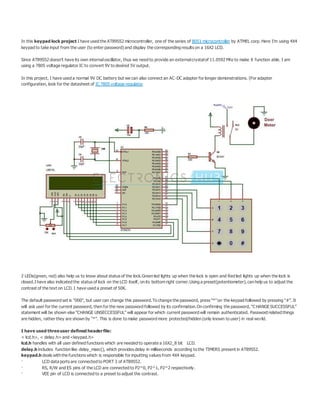
- 1. In this keypad lock project I have used the AT89S52 microcontroller, one of the series of 8051 microcontroller by ATMEL corp. Here I’m using 4X4 keypad to take input from the user (to enter password) and display the corresponding results on a 16X2 LCD. Since AT89S52 doesn’t have its own internaloscillator, thus we need to provide an externalcrystalof 11.0592 Mhz to make it function able. I am using a 7805 voltage regulator IC to convert 9V to desired 5V output. In this project, I have used a normal 9V DC battery but we can also connect an AC-DC adapter for longer demonstrations. (For adapter configuration, look for the datasheet of IC 7805 voltage regulator 2 LEDs(green, red) also help us to know about status of the lock.Green led lights up when the lock is open and Red led lights up when the lock is closed.I have also indicated the status of lock on the LCD itself, on its bottom right corner.Using a preset(potentiometer), can help us to adjust the contrast of the text on LCD. I have used a preset of 50K. The default password set is “000”, but user can change this password.To change the password, press “*”on the keypad followed by pressing “#”. It will ask user for the current password, then for the new password followed by its confirmation.On confirming the password, “C HANGE SUCCESSFUL” statement will be shown else “CHANGE UNSECCESSFUL” will appear for which current password will remain authenticated. Password related things are hidden, rather they are shown by “*”. This is done to make password more protected/hidden (only known to user) in real world. I have used threeuser defined headerfile: < lcd.h>, < delay.h> and <keypad.h> lcd.h handles with all user defined functions which are needed to operate a 16X2_8 bit LCD. delay.h includes function like delay_msec(), which provides delay in milliseconds according to the TIMERS present in AT89S52. keypad.h deals with the functions which is responsible for inputting values from 4X4 keypad. · LCD data ports are connected to PORT 3 of AT89S52. · RS, R/W and ES pins of the LCD are connected to P2^0, P2^1, P2^2 respectively. · VEE pin of LCD is connected to a preset to adjust the contrast.
- 2. · Pins 15 & 16 of LCD are connected to VCC & GND respectively. · The 8 pins of the Keypad are connected to PORT 1 of AT89S52. · The GREEN LED is connected to P2^4 and RED LED to P2^3. Peripherals that can be attached: · We can use a linear actuator systemto provide a mechanical locking system · We can also use a magnetic systemfor doing the same. · Using a stepper motor/servo motor controlled system in also a good idea.
- 4. PROGRAMMING #include<reg51.h> #define portP1 #define dataportP3 #define keyP0 #define sec100 sbitrs = P2^0; sbitrw = P2^1; sbiten= P2^2; sbitcol1=P1^4; sbitcol2=P1^5; sbitcol3=P1^6;
- 5. sbitrow1=P1^0; sbitrow2=P1^1; sbitrow3=P1^2; sbitrow4=P1^3; sbitlock_output=P2^3; sbitopen_output=P2^4; intcheck=0; intdigit[4]={0,0,0,0}; intdig_input[4]={0,0,0,0}; intdig_input_recheck[4]={0,0,0,0}; inti,k; voiddelay(unsigned intmsec) //Time delayfunction { inti,j ; for(i=0;i<msec;i++) for(j=0;j<1275;j++); } voidlcd_cmd(unsignedcharitem) //FunctiontosendcommandtoLCD { dataport= item;
- 6. rs= 0; rw=0; en=1; delay(1); en=0; return; } voidlcd_data(unsignedcharitem) //Functiontosenddatato LCD { dataport= item; rs= 1; rw=0; en=1; delay(1); en=0; return; } voidlcd_data_string(unsignedchar*str) // Functiontosenddata to string { inti=0; while(str[i]!='0') { lcd_data(str[i]);
- 8. open_output=0; while(1); } else { lcd_cmd(0x01); lcd_cmd(0x82); lcd_data_string("WRONGPASSWORD"); lock_output=1; open_output=0; delay(300); } } voidcode_check() //Functiontocheckpassword { if(i<=3) { switch((i+1)) { case 1: { if(dig_input[0]==digit[0]) { check=check+1; }
- 9. break; } case 2: { if(dig_input[1]==digit[1]) { check=check+1; } break; } case 3: { if(dig_input[2]==digit[2]) { check=check+1; } break; } case 4: { if(dig_input[3]==digit[3]) { check=check+1; } break; } } }
- 10. delay(10); if(i==3) { ans(); } } voiddisplay(inta) //Displayfunction { switch(a) { case 1:{ lcd_data('*'); digit[i]=1; code_check(); break; } case 2:{ lcd_data('*'); digit[i]=2; code_check(); break; }
- 11. case 3:{ lcd_data('*'); digit[i]=3; code_check(); break; } case 4:{ lcd_data('*'); digit[i]=4; code_check(); break; } case 5:{ lcd_data('*'); digit[i]=5; code_check(); break; } case 6:{ lcd_data('*'); digit[i]=6;
- 12. code_check(); break; } case 7:{ lcd_data('*'); digit[i]=7; code_check(); break; } case 8:{ lcd_data('*'); digit[i]=8; code_check(); break; } case 9:{ lcd_data('*'); digit[i]=9; code_check(); break; } case 0:{
- 18. if(col3==0) dig_input[k]=3; row1=1; row2=0; if(col3==0) dig_input[k]=6; row2=1; row3=0; if(col3==0) dig_input[k]=9; row3=1; row4=0; if(col3==0) { row4=1; } } voidpass_set() { row1=row2=row3=row4=0; while(col1==1&& col2==1 && col3==1); for(i=0;i<4;i++) { k=i;
- 19. delay(50); lcd_cmd(0xc4+i); delay(10); row1=row2=row3=row4=0; while(col1==1&& col2==1 && col3==1); row1=row2=row3=row4=0; if(col1==0) check_password_col1(); else if(col2==0) check_password_col2(); else if(col3==0) check_password_col3(); lcd_data('*'); delay(10); } } voidmain() { inte,j=0,count=1; lock_output=0; open_output=0; col1=col2=col3=1;
- 21. } } while(j<4); while(count<4) //Code inputandcheck { lcd_cmd(0x01); lock_output=0; lcd_cmd(0x82); lcd("ENTERPASSWORD"); check=0; row1=row2=row3=row4=0; while(col1==1&& col2==1 && col3==1); for(i=0;i<4;i++) { delay(10); lcd_cmd(0xc4+i); row1=row2=row3=row4=0; while(col1==1&& col2==1 && col3==1); row1=row2=row3=row4=0; if(col1==0) check_col1(); else if(col2==0) check_col2();