2. Copyright NFPA
high-expansion foam systems have been included.
The 2005 edition reorganizes the requirements for low-, medium-, and high-expansion foam
to better incorporate the requirements of NFPA 11A.
Technical Committee on Foam
Christopher P. Hanauska, Chair
Hughes Associates, Inc., MD [SE]
Jean-Pierre Asselin, FireFlex Systems, Inc., Canada [M]
V. Frank Bateman, Kidde Fire Fighting, CA [M]
Gene E. Benzenberg, Alison Control Incorporated, NJ [M]
W. D. Cochran, Verde Environmental, TX [M]
Arthur R. Dooley, Jr., Dooley Tackaberry, Inc., TX [IM]
Rep. National Association of Fire Equipment Distributors
Robert A. Green, Public Service Electric & Gas Company, NJ [U]
Rep. Edison Electric Institute
Randall Hendricksen, ChemGuard, Incorporated, TX [M]
Eldon D. Jackson, The Viking Corporation, MI [M]
Rep. National Fire Sprinkler Association
Kevin P. Kuntz, Marsh USA Inc., NJ [I]
Eric LaVergne, Williams Fire and Hazard Control, TX [M]
Joan M. Leedy, Dyne Technologies, MN [IM]
Ronald Mahlman, The RJA Group, Inc., CA [SE]
Robert C. Merritt, FM Global, MA [I]
Rep. FM Global/FM Engineering & Research
Edward C. Norman, Aqueous Foam Technology, Inc., PA [SE]
Keith Olson, Tyco Suppression Systems, WI [M]
David W. Owen, ExxonMobil Corporation, VA [U]
Rep. American Petroleum Institute
Michael F. Pierson, CSC Advanced Marine, DC [SE]
3. Copyright NFPA
Fay Purvis, Vector Fire Technology, Inc., PA [SE]
Niall Ramsden, Resource Protection International, England [SE]
Lynn A. Rawls, GE Global Asset Protection Services, MS [I]
Rep. GE Global Asset Protection Services
Tom Reser, Edwards Manufacturing, OR [M]
Gaston “Gus” J. Santerre, Integrated Protection Services Inc., CA [IM]
Rep. American Fire Sprinkler Association
Orville M. Slye, Jr., Loss Control Associates Inc., PA [SE]
Howard L. Vandersall, Lawdon Fire Services, Inc., CA [SE]
Klaus Wahle, U.S. Coast Guard, DC [E]
Michel Williams, Ultramar Canada, Ltd., Canada [U]
Rep. NFPA Industrial Fire Protection Section
Kenneth W. Zastrow, Underwriters Laboratories Inc., IL [RT]
Alternates
Randall Eberly, U.S. Coast Guard Headquarters, DC [E]
(Alt. to K. Wahle)
Mitchell Hubert, Ansul Incorporated/Tyco International, WI [M]
(Alt. to K. Olson)
William E. Janz, GE Global Asset Protection Services, IL [I]
(Alt. to L. A. Rawls)
George E. Laverick, Underwriters Laboratories Inc., IL [RT]
(Alt. to K. W. Zastrow)
Raymond Quenneville, FireFlex Systems, Inc., Canada [M]
(Alt. to J.-P. Asselin)
Joseph L. Scheffey, Hughes Associates, Inc., MD [SE]
(Alt. to C. P. Hanauska)
Donald H. Seaman, CSC Advanced Marine, DC [SE]
(Alt. to M. F. Pierson)
Clark D. Shepard, ExxonMobil Corporation, VA [U]
4. Copyright NFPA
(Alt. to D. W. Owen)
John A. Toney, Dooley Tackaberry, Inc., TX [IM]
(Alt. to A. R. Dooley)
Nonvoting
Richard F. Murphy, Cranford, NJ [SE]
(Member Emeritus)
David R. Hague, NFPA Staff Liaison
This list represents the membership at the time the Committee was balloted on the final text of
this edition. Since that time, changes in the membership may have occurred. A key to
classifications is found at the back of the document.
NOTE: Membership on a committee shall not in and of itself constitute an endorsement of the
Association or any document developed by the committee on which the member serves.
Committee Scope: This Committee shall have primary responsibility for documents on the
installation, maintenance, and use of foam systems for fire protection, including foam hose
streams.
NFPA 11
Standard for
Low-, Medium-, and High-Expansion Foam
2005 Edition
IMPORTANT NOTE: This NFPA document is made available for use subject to
important notices and legal disclaimers. These notices and disclaimers appear in all
publications containing this document and may be found under the heading “Important
Notices and Disclaimers Concerning NFPA Documents.” They can also be obtained on
request from NFPA or viewed at www.nfpa.org/disclaimers.
NOTICE: An asterisk (*) following the number or letter designating a paragraph indicates
that explanatory material on the paragraph can be found in Annex A.
Changes other than editorial are indicated by a vertical rule beside the paragraph, table, or
figure in which the change occurred. These rules are included as an aid to the user in
identifying changes from the previous edition. Where one or more complete paragraphs
have been deleted, the deletion is indicated by a bullet (•) between the paragraphs that
remain.
A reference in brackets [ ] following a section or paragraph indicates material that has been
extracted from another NFPA document. As an aid to the user, the complete title and edition
of the source documents for mandatory extracts are given in Chapter 2 and those for
nonmandatory extracts are given in Annex I. Editorial changes to extracted material consist
of revising references to an appropriate division in this document or the inclusion of the
document number with the division number when the reference is to the original document.
Requests for interpretations or revisions of extracted text shall be sent to the technical
5. Copyright NFPA
committee responsible for the source document.
Information on referenced publications can be found in Chapter 2 and Annex I.
Chapter 1 Administration
1.1* Scope.
1.1.1 This standard covers the design, installation, operation, testing, and maintenance of
low-, medium-, and high-expansion foam systems for fire protection.
1.1.2 It is not the intent of this standard to specify where foam protection is required.
1.2 Purpose.
1.2.1 This standard is intended for the use and guidance of those responsible for designing,
installing, testing, inspecting, approving, listing, operating, or maintaining fixed, semifixed,
or portable low-, medium-, and high-expansion foam fire-extinguishing systems for interior
or exterior hazards.
1.2.2 Nothing in this standard is intended to restrict new technologies or alternative
arrangements, provided the level of safety prescribed by the standard is not lowered.
1.3 Application.
This standard is not applicable to the following types of systems:
(1) Chemical foams and systems (considered obsolete)
(2) Deluge foam-water sprinkler or spray systems (See NFPA 16.)
(3) Foam-water closed-head sprinkler systems (See NFPA 16.)
(4) Combined agent systems
(5) Mobile foam apparatus (See NFPA 1901.)
(6) Class A foam and systems (See NFPA 1150.)
1.4 Retroactivity.
The provisions of this standard reflect a consensus of what is necessary to provide an
acceptable degree of protection from the hazards addressed in this standard at the time the
standard was issued.
1.4.1 Unless otherwise specified, the provisions of this standard shall not apply to facilities,
equipment, structures, or installations that existed or were approved for construction or
installation prior to the effective date of the standard. Where specified, the provisions of this
standard shall be retroactive.
1.4.2 In those cases where the authority having jurisdiction determines that the existing
situation presents an unacceptable degree of risk, the authority having jurisdiction shall be
permitted to apply retroactively any portions of this standard deemed appropriate.
6. Copyright NFPA
1.4.3 The retroactive requirements of this standard shall be permitted to be modified if their
application clearly would be impractical in the judgment of the authority having
jurisdiction, and only where it is clearly evident that a reasonable degree of safety is
provided.
1.5 Equivalency.
Nothing in this standard is intended to prevent the use of systems, methods, or devices of
equivalent or superior quality, strength, fire resistance, effectiveness, durability, and safety
over those prescribed by this standard.
1.5.1 Technical documentation shall be submitted to the authority having jurisdiction to
demonstrate equivalency.
1.5.2 The system, method, or device shall be approved for the intended purpose by the
authority having jurisdiction.
1.6 Units and Formulas.
Metric units of measurement in this standard are in accordance with the modernized metric
system known as the International System of Units (SI). The liter unit, which is not part of
but is recognized by SI, is commonly used in international fire protection. Conversion
factors for this unit are found in Table 1.6.
Table 1.6 Metric Units of Measure
Name of Unit Unit Symbol Conversion Factor
liter L 1 gal = 3.785 L
liter per minute
per square
meter
L/min m2 1 gpm/ft2 = 40.746 L/min
m2
cubic decimeter dm3 1 gal = 3.785 dm3
pascal Pa 1 psi = 6894.757 Pa
bar bar 1 psi = 0.0689 bar
bar bar 1 bar = 105 Pa
kilopascal kPa 1 psi = 6.895 kPa
Note: For additional conversions and information, see
IEEE/ASTM SI 10.
Chapter 2 Referenced Publications
2.1 General.
The documents or portions thereof listed in this chapter are referenced within this standard
and shall be considered part of the requirements of this document.
2.2 NFPA Publications.
7. Copyright NFPA
National Fire Protection Association, 1 Batterymarch Park, Quincy, MA 02169-7471.
NFPA 13, Standard for the Installation of Sprinkler Systems, 2002 edition.
NFPA 15, Standard for Water Spray Fixed Systems for Fire Protection, 2001 edition.
NFPA 16, Standard for the Installation of Foam-Water Sprinkler and Foam-Water Spray
Systems, 2003 edition.
NFPA 20, Standard for the Installation of Stationary Pumps for Fire Protection, 2003
edition.
NFPA 24, Standard for the Installation of Private Fire Service Mains and Their
Appurtenances, 2002 edition.
NFPA 30, Flammable and Combustible Liquids Code, 2003 edition.
NFPA 70, National Electrical Code®, 2005 edition.
NFPA 72®, National Fire Alarm Code®, 2002 edition.
NFPA 1150, Standard on Foam Chemicals for Fires in Class A Fuels, 2004 edition.
NFPA 1901, Standard for Automotive Fire Apparatus, 2003 edition.
NFPA 1961, Standard on Fire Hose, 2002 edition.
2.3 Other Publications.
2.3.1 ANSI Publications.
American National Standards Institute, Inc., 11 West 43rd St., 4th Floor, New York, NY
10036.
ANSI B1.20.1, Pipe Threads, 1992.
ANSI B16.1, Cast Iron Pipe Flanges and Flanged Fittings, 1989.
ANSI B16.3, Malleable Iron Threaded Fittings, 1992.
ANSI B16.4, Gray Iron Threaded Fittings, 1992.
ANSI B16.5, Pipe Flanges and Flanged Fittings, 1996.
ANSI B16.9, Factory-Made Wrought Steel Buttwelding Fittings, 2001.
ANSI B16.11, Forged Fittings, Socket-Welding and Threaded, 2001.
ANSI B16.25, Buttwelding Ends, 1992.
2.3.2 API Publication.
American Petroleum Institute, 1220 L Street, N.W., Washington, DC 20005-4070.
API 650, Welded Steel Tanks for Oil Storage, 1998.
2.3.3 ASTM Publications.
American Society for Testing and Materials, 100 Barr Harbor Drive, West Conshohocken,
8. Copyright NFPA
PA 19428-2959.
ASTM A 53, Standard Specification for Pipe, Steel, Black and Hot-Dipped, Zinc-Coated,
Welded and Seamless, 2001.
ASTM A 105, Standard Specification for Carbon Steel Forgings for Piping Applications,
2001.
ASTM A 106, Standard Specification for Seamless Carbon Steel Pipe for
High-Temperature Service, 1999.
ASTM A 135, Standard Specification for Electric Resistance-Welded Pipe, 2001.
ASTM A 182, Standard Specification for Forged or Rolled Alloy-Steel Pipe Flanges,
Forged Fittings, and Valves and Parts for High-Temperature Service, 2001.
ASTM A 216, Standard Specification for Steel Castings, Carbon, Suitable for Fusion
Welding for High-Temperature Service, 1998.
ASTM A 234, Standard Specification for Piping Fittings of Wrought Carbon Steel and
Alloy Steel for Moderate and Elevated Temperatures, 2001.
ASTM A 312, Standard Specification for Seamless and Welded Austenitic Stainless Steel
Pipes, 2001.
ASTM A 395, Standard Specification for Ferritic Ductile Iron Pressure-Retaining Castings
for Use at Elevated Temperatures, 1999.
ASTM A 795, Standard Specification for Black and Hot-Dipped, Zinc-Coated,
(Galvanized) Welded and Seamless Steel Pipe for Fire Protection Use, 2000.
IEEE/ASTM SI 10, American National Standard for Use of the International System of
Units (SI): The Modern Metric System, 2002.
2.3.4 AWS Publication.
American Welding Society, 550 N.W. LeJeune Road, Miami, FL 33126.
AWS D10.9, Standard for the Qualification of Welding Procedures and Welders for Piping
and Tubing, 1980.
2.3.5 IEEE Publication.
Institute of Electrical and Electronics Engineers, Three Park Avenue, 17th Floor, New
York, NY 10016-5997.
IEEE 45, Recommended Practice for Electric Installations, 1983.
2.3.6 IMO Publication.
International Maritime Organization, 4 Albert Embankment, London SE1 7SR.
Safety of Life at Sea, SOLAS Regulations II-2/4.3 and 4.3.5.
2.3.7 UL Publication.
Underwriters Laboratories Inc., 333 Pfingsten Road, Northbrook, IL 60062-2096.
9. Copyright NFPA
UL 162, Standard for Safety Foam Equipment and Liquid Concentrates, 1994 with
revisions through September 8, 1999.
Chapter 3 Definitions
3.1 General.
The definitions contained in this chapter shall apply to the terms used in this standard.
Where terms are not defined in this chapter or within another chapter, they shall be defined
using their ordinarily accepted meanings within the context in which they are used.
Merriam-Webster's Collegiate Dictionary, 11th edition, shall be the source for the
ordinarily accepted meaning.
3.2 NFPA Official Definitions.
3.2.1* Approved. Acceptable to the authority having jurisdiction.
3.2.2* Authority Having Jurisdiction (AHJ). An organization, office, or individual
responsible for enforcing the requirements of a code or standard, or for approving
equipment, materials, an installation, or a procedure.
3.2.3 Labeled. Equipment or materials to which has been attached a label, symbol, or other
identifying mark of an organization that is acceptable to the authority having jurisdiction
and concerned with product evaluation, that maintains periodic inspection of production of
labeled equipment or materials, and by whose labeling the manufacturer indicates
compliance with appropriate standards or performance in a specified manner.
3.2.4* Listed. Equipment, materials, or services included in a list published by an
organization that is acceptable to the authority having jurisdiction and concerned with
evaluation of products or services, that maintains periodic inspection of production of listed
equipment or materials or periodic evaluation of services, and whose listing states that
either the equipment, material, or service meets appropriate designated standards or has
been tested and found suitable for a specified purpose.
3.2.5 Shall. Indicates a mandatory requirement.
3.2.6 Should. Indicates a recommendation or that which is advised but not required.
3.2.7 Standard. A document, the main text of which contains only mandatory provisions
using the word “shall” to indicate requirements and which is in a form generally suitable for
mandatory reference by another standard or code or for adoption into law. Nonmandatory
provisions shall be located in an appendix or annex, footnote, or fine-print note and are not
to be considered a part of the requirements of a standard.
3.3 General Definitions.
3.3.1 Combustible Liquid. A liquid that has a closed-cup flash point at or above 37.8°C
(100°F). [30, 2003]
3.3.1.1 Combustible Liquid Classification.
10. Copyright NFPA
3.3.1.1.1 Combustible Liquid Class II. Any liquid that has a flash point at or above 37.8°C
(100°F) and below 60°C (140°F). [30, 2003]
3.3.1.1.2 Combustible Liquid Class IIIA. Any liquid that has a flash point at or above 60°C
(140°F), but below 93°C (200°F). [30, 2003]
3.3.1.1.3 Combustible Liquid Class IIIB. Any liquid that has a flash point at or above 93°C
(200°F). [30, 2003]
3.3.2* Concentration. The percent of foam concentrate contained in a foam solution.
3.3.3 Coupled Water-Motor Pump. A correctly designed positive displacement pump in
the water supply line coupled to a second, smaller, positive displacement foam concentrate
pump to provide proportioning.
3.3.4 Discharge Device. A device designed to discharge water or foam-water solution in a
predetermined, fixed, or adjustable pattern. Examples include, but are not limited to,
sprinklers, spray nozzles, and hose nozzles.
3.3.4.1 Air-Aspirating Discharge Devices. Devices specially designed to aspirate and mix
air into the foam solution to generate foam, followed by foam discharge in a specific design
pattern.
3.3.4.2* Non-Air-Aspirating Discharge Devices. Devices designed to provide a specific
water discharge pattern.
3.3.5 Discharge Outlet.
3.3.5.1 Fixed Foam Discharge Outlet. A device permanently attached to a tank, dike, or
other containment structure, designed to introduce foam.
3.3.5.2 Type I Discharge Outlet. An approved discharge outlet that conducts and delivers
foam gently onto the liquid surface without submergence of the foam or agitation of the
surface.
3.3.5.3 Type II Discharge Outlet. An approved discharge outlet that does not deliver foam
gently onto the liquid surface but is designed to lessen submergence of the foam and
agitation of the surface.
3.3.6* Eductor (Inductor). A device that uses the Venturi principle to introduce a
proportionate quantity of foam concentrate into a water stream; the pressure at the throat is
below atmospheric pressure and will draw in liquid from atmospheric storage.
3.3.6.1* In-Line Eductor. A Venturi-type proportioning device that meters foam
concentrate at a fixed or variable concentration into the water stream at a point between the
water source and a nozzle or other discharge device.
3.3.7 Expansion. The ratio of final foam volume to original foam solution volume.
3.3.8 Fire.
3.3.8.1 Class A. Fire in ordinary combustible materials, such as wood, cloth, paper, rubber,
and many plastics.
11. Copyright NFPA
3.3.8.2 Class B. Fires in flammable liquids, combustible liquids, petroleum greases, tars,
oils, oil-based paints, solvents, lacquers, alcohols, and flammable gases.
3.3.9 Flammable Liquid. A liquid that has a closed-cup flash point that is below 37.8°C
(100°F) and a maximum vapor pressure of 2068 mm Hg (40 psia) at 37.8°C (100°F). [30,
2003]
3.3.9.1 Flammable Liquid Classification.
3.3.9.1.1 Flammable Liquid Class I. Any liquid that has a closed-cup flash point below
37.8°C (100°F) and a Reid vapor pressure not exceeding 2068.6 mm Hg (40 psia) at 37.8°C
(100°F). [30, 2003]
3.3.9.1.2 Flammable Liquid Class IA. Any liquid that has a flash point below 22.8°C
(73°F) and a boiling point below 37.8°C (100°F). [30, 2003]
3.3.9.1.3 Flammable Liquid Class IB. Any liquid that has a flash point below 22.8°C
(73°F) and a boiling point at or above 37.8°C (100°F). [30, 2003]
3.3.9.1.4 Flammable Liquid Class IC. Any liquid that has a flash point at or above 22.8°C
(73°F) but below 37.8°C (100°F). [30, 2003]
3.3.10* Foam. A stable aggregation of small bubbles of lower density than oil or water that
exhibits a tenacity for covering horizontal surfaces.
3.3.11 Foam Chamber. See 3.3.5.1, Fixed Foam Discharge Outlet.
3.3.12* Foam Concentrate. A concentrated liquid foaming agent as received from the
manufacturer.
3.3.12.1* Alcohol-Resistant Foam Concentrate. A concentrate used for fighting fires on
water-soluble materials and other fuels destructive to regular, AFFF, or FFFP foams, as
well as for fires involving hydrocarbons.
3.3.12.2* Aqueous Film-Forming Foam Concentrate (AFFF). A concentrate based on
fluorinated surfactants plus foam stabilizers and usually diluted with water to a 1 percent, 3
percent, or 6 percent solution.
3.3.12.3* Fluoroprotein Foam Concentrate. A concentrate very similar to protein-foam
concentrate but with a synthetic fluorinated surfactant additive.
3.3.12.3.1* Film-Forming Fluoroprotein Foam Concentrate (FFFP). A concentrate that
uses fluorinated surfactants to produce a fluid aqueous film for suppressing hydrocarbon
fuel vapors.
3.3.12.4* Medium- and High-Expansion Foam Concentrate. A concentrate, usually
derived from hydrocarbon surfactants, used in specially designed equipment to produce
foams having foam-to-solution volume ratios of 20:1 to approximately 1000:1.
3.3.12.5* Protein Foam Concentrate. Concentrate consisting primarily of products from a
protein hydrolysate, plus stabilizing additives and inhibitors to protect against freezing, to
prevent corrosion of equipment and containers, to resist bacterial decomposition, to control
viscosity, and to otherwise ensure readiness for use under emergency conditions.
12. Copyright NFPA
3.3.12.6 Synthetic Foam Concentrate. Concentrate based on foaming agents other than
hydrolyzed proteins and including aqueous film-forming foam (AFFF) concentrates,
medium- and high-expansion foam concentrates, and other synthetic foam concentrates.
3.3.12.6.1* Other Synthetic Foam Concentrate. A concentrate based on hydrocarbon
surface active agents and listed as a wetting agent, foaming agent, or both.
3.3.13 Foam Concentrate Type. A classification of a foam concentrate that includes the
chemical composition as defined under foam concentrate (see 3.3.12), including the use
percentage, the minimum usable temperature, and the fuels on which the concentrate is
effective.
3.3.14 Foam Generators.
3.3.14.1 Foam Generators — Aspirator Type. Foam generators, fixed or portable, in which
jet streams of foam solution aspirate sufficient amounts of air that is then entrained on the
screens to produce foam, and which usually produce foam with expansion ratios of not
more than 250:1.
3.3.14.2* Foam Generators — Blower Type. Foam generators, fixed or portable, in which
the foam solution is discharged as a spray onto screens through which an airstream
developed by a fan or blower is passing.
3.3.15 Foam Injection.
3.3.15.1 Semisubsurface Foam Injection. Discharge of foam at the liquid surface within a
storage tank from a floating hose that rises from a piped container near the tank bottom.
3.3.15.2 Subsurface Foam Injection. Discharge of foam into a storage tank from an outlet
near the tank bottom.
3.3.16* Foam Solution. A homogeneous mixture of water and foam concentrate in the
correct proportions.
3.3.16.1 Premixed Foam Solution. Solution produced by introducing a measured amount of
foam concentrate into a given amount of water in a storage tank.
3.3.17 Foam System Types.
3.3.17.1 Fixed System. A complete installation in which foam is piped from a central foam
station, discharging through fixed delivery outlets to the hazard to be protected with
permanently installed pumps where required.
3.3.17.2* Mobile System. Any type of foam-producing unit that is mounted on wheels and
that is self-propelled or towed by a vehicle and can be connected to a water supply or can
utilize a premixed foam solution.
3.3.17.3 Portable System. Foam-producing equipment, materials, hose, and so forth, that
are transported by hand.
3.3.17.4* Semifixed System. A system in which the hazard is equipped with fixed discharge
outlets connected to piping that terminates at a safe distance.
3.3.18* Foam-Generating Methods. Methods of generation of air foam including hose
13. Copyright NFPA
stream, foam nozzle, and medium- and high-expansion generators, foam maker, pressure
foam maker (high back pressure or forcing type), or foam monitor stream.
3.3.19* Handline. A hose and nozzle that can be held and directed by hand.
3.3.20 Monitor.
3.3.20.1* Fixed Monitor (Cannon). A device that delivers a large foam stream and is
mounted on a stationary support that either is elevated or is at grade.
3.3.20.2 Portable Monitor (Cannon). A device that delivers a foam monitor stream and is
mounted on a movable support or wheels so it can be transported to the fire scene.
3.3.21 Nozzle.
3.3.21.1* Foam Nozzle or Fixed Foam Maker. A specially designed hoseline nozzle or
fixed foam maker designed to aspirate air that is connected to a supply of foam solution.
3.3.21.2* Self-Educting Nozzle. A device that incorporates a venturi to draw foam
concentrate through a short length of pipe and/or flexible tubing connected to the foam
supply.
3.3.22* Pressure Foam Maker (High Back-Pressure or Forcing Type). A foam maker
utilizing the Venturi principle for aspirating air into a stream of foam solution forms foam
under pressure.
3.3.23* Pressure Proportioning Tank. A foam concentrate tank with no bladder that uses
water flow through an orifice to displace the foam concentrate in the tank with water to add
foam concentrate through an orifice into a water line at a specified rate. This device is only
suitable for foams having a specific gravity of at least 1.15.
3.3.24 Balanced Pressure Bladder Tank. A foam concentrate tank fitted with an internal
bladder which uses water flow through a modified venturi type proportioner to control the
foam concentrate injection rate by displacing the foam concentrate within the bladder with
water outside the bladder.
3.3.25 Proportioning. The continuous introduction of foam concentrate at the
recommended ratio into the water stream to form foam solution.
3.3.25.1* Balanced Pressure Pump-Type Proportioning. A foam proportioning system that
utilizes a foam pump and valve(s) to balance foam and water pressures at a modified
venturi-type proportioner located in the foam solution delivery piping; a foam concentrate
metering orifice is fitted in the foam inlet section of the proportioner.
3.3.25.1.1* In-Line Balanced Pressure Proportioning. A foam proportioning system
utilizing a foam concentrate pump at all design flow rates, the constant pressure of which is
greater than the maximum water pressure under all operating conditions.
3.3.25.2* Direct Injection Variable Pump Output Proportioning. A direct injection
proportioning system that utilizes flowmeters for foam concentrate and water in conjunction
with a variable output foam pump control system.
3.3.26 Proportioning Methods for Foam Systems. The methods of proportioning used to
14. Copyright NFPA
create the correct solution of water and foam liquid concentrate.
3.3.27* Pump Proportioner (Around-the-Pump Proportioner). A system that uses a
venturi eductor installed in a bypass line between the discharge and suction side of a water
pump and suitable variable or fixed orifices to induct foam concentrate from a tank or
container into the pump suction line.
3.3.28 Stream.
3.3.28.1 Foam Hose Stream. A foam stream from a handline.
3.3.28.2 Foam Monitor Stream. A large capacity foam stream from a nozzle that is
supported in position and can be directed by one person.
Chapter 4 System Components and System Types
4.1* General.
This chapter shall provide requirements for the correct use of foam system components.
4.1.1 All components shall be listed for their intended use.
4.1.2 Where listings for components do not exist, components shall be approved.
4.2 Water Supplies.
4.2.1 Water Supplies, Including Premix Solution.
4.2.1.1 Quality.
4.2.1.1.1 The water supply to foam systems shall be permitted to be hard or soft, fresh or
salt, but shall be of a quality such that adverse effects on foam formation or foam stability
do not occur.
4.2.1.1.2 No corrosion inhibitors, emulsion breaking chemicals, or any other additives shall
be present without prior consultation with the foam concentrate supplier.
4.2.1.2* Quantity. The water supply shall be of a quantity to supply all the devices that
shall be permitted to be used simultaneously for the specified time.
4.2.1.2.1 This quantity shall include not only the volume required for the foam apparatus
but also water that can be used in other fire-fighting operations, in addition to the normal
plant requirements.
4.2.1.2.2 Premixed solution-type systems shall not be required to be provided with a
continuous water supply.
4.2.1.3 Pressure. The pressure available at the inlet to the foam system (e.g., foam
generator, air foam maker) under required flow conditions shall be at least the minimum
pressure for which the system has been designed.
4.2.1.4* Temperature. Optimum foam production shall be obtained by using water at
temperatures between 4°C (40°F) and 37.8°C (100°F).
15. Copyright NFPA
4.2.1.5 Design. The water system shall be designed and installed in accordance with NFPA
24.
4.2.1.5.1 Strainers shall be provided where solids of a size large enough to obstruct
openings or damage equipment are present.
4.2.1.5.2 Hydrants furnishing the water supply for foam equipment shall be provided in the
required number.
4.2.1.5.3 Hydrants shall be located as required by the authority having jurisdiction (AHJ).
4.2.1.6 Storage. Water supply or premixed solution shall be protected against freezing in
climates where freezing temperatures are expected.
4.2.2 Water and Foam Concentrate Pumps.
4.2.2.1 When water or foam concentrate pumps are required for automatic foam system
operation, they shall be designed and installed in accordance with NFPA 20.
4.2.2.2 Controllers in accordance with NFPA 20 shall not be required for manual systems.
4.3 Foam Concentrates.
4.3.1 Types of Foam Concentrate.
4.3.1.1 Foam concentrate shall be listed.
4.3.1.2* The concentrate used in a foam system shall be listed for use on the specific
flammable or combustible liquid to be protected.
4.3.1.3 The limitations of the listing and the manufacturers' specifications shall be
followed.
4.3.1.4 Foam concentrates for protection of hydrocarbon fuels shall be one of the following
types:
(1) Protein
(2) Fluoroprotein
(3) Aqueous film-forming foam (AFFF)
(4) Film-forming fluoroprotein (FFFP)
(5) Alcohol-resistant
(6) High-expansion
(7) Medium-expansion
(8) Others listed for this purpose
4.3.1.5 Water-miscible and polar flammable or combustible liquids shall be protected by
alcohol-resistant concentrates listed for this purpose.
4.3.2 Concentrate Storage.
16. Copyright NFPA
4.3.2.1 Storage Facilities.
4.3.2.1.1 Foam concentrates and equipment shall be stored in a location not exposed to the
hazard they protect.
4.3.2.1.2 If housed, foam concentrates and equipment shall be in a noncombustible
structure.
4.3.2.1.3 For outdoor nonautomatic systems, the AHJ shall be permitted to approve the
storage of foam concentrate in a location off premises where these supplies are available at
all times.
4.3.2.1.4 Loading and transportation facilities for foam concentrates shall be provided.
4.3.2.1.5 Off-premises supplies shall be of the type required for use in the systems of the
given installation.
4.3.2.1.6 At the time of a fire, these off-premises supplies shall be accumulated in the
required quantities, before the equipment is placed in operation, to ensure uninterrupted
foam production at the design rate for the required period of time.
4.3.2.2* Quantity. The amount of concentrate shall be at least sufficient for the largest
single hazard protected or group of hazards that are to be protected simultaneously.
4.3.2.3 Foam Concentrate Storage Tanks.
4.3.2.3.1 Bulk liquid storage tanks shall be fabricated from or be lined with materials
compatible with the concentrate.
4.3.2.3.2 The storage tank shall be designed to minimize evaporation of foam concentrate.
4.3.2.4 Storage Conditions.
4.3.2.4.1* In order to ensure the correct operation of any foam-producing system, the
chemical and physical characteristics of the materials comprising the system shall be taken
into consideration in design.
4.3.2.4.2* Foam concentrates shall be stored within the listed temperature limitations.
4.3.2.4.3 Markings shall be provided on storage vessels to identify the type of concentrate
and its intended concentration in solution.
4.3.2.5 Foam Concentrate Supply.
4.3.2.5.1 Foam Concentrate Consumption Rates. The consumption rates shall be based
on the percentage concentrate used in the system design (e.g., 3 percent or 6 percent or
other, if so listed or approved by the AHJ).
4.3.2.5.2 Reserve Supply of Foam Concentrate.
4.3.2.5.2.1 There shall be a reserve supply of foam concentrate to meet design requirements
in order to put the system back into service after operation.
4.3.2.5.2.2 The reserve supply shall be in separate tanks or compartments, in drums or cans
on the premises, or available from an approved outside source within 24 hours.
17. Copyright NFPA
4.3.2.6 Auxiliary Supplies. Other equipment necessary to recommission the system, such
as bottles of nitrogen or carbon dioxide for premix systems, also shall be available.
4.4 Concentrate Compatibility.
4.4.1 Compatibility of Foam Concentrates.
4.4.1.1* Different types of foam concentrates shall not be mixed for storage.
4.4.1.2 Different brands of the same type of concentrate shall not be mixed unless data are
provided by the manufacturer to and accepted by the AHJ to prove that they are compatible.
4.4.1.3 Low-expansion foams generated separately from protein, fluoroprotein, FFFP, and
AFFF concentrates shall be permitted to be applied to a fire in sequence or simultaneously.
4.4.2* Foam Compatibility with Dry Chemical Agents.
4.4.2.1 The manufacturers of the dry chemical and foam concentrate to be used in the
system shall confirm that their products are mutually compatible.
4.4.2.2 Where used, limitations imposed on either of the agents alone shall be applied.
4.5 Foam Proportioning.
The method of foam proportioning shall conform to one of the following:
(1) Self-educting nozzle
(2) In-line eductor
(3) Pressure proportioners (with or without bladder)
(4) Around-the-pump proportioners
(5) Direct injection variable output foam pump system
(6) Coupled-water motor pump
(7) Balanced pressure pump-type proportioners
4.6* Foam Concentrate Pumps.
4.6.1 The design and materials of construction for foam concentrate pumps shall be in
accordance with NFPA 20.
4.6.2 Special attention shall be paid to the type of seal or packing used. Seals or packing
used shall be compatible with the foam concentrate.
4.6.3 Foam concentrate pumps shall have adequate capacities to meet the maximum system
demand.
4.6.4 To ensure positive injection of concentrates, the discharge pressure ratings of pumps
at the design discharge capacity shall be in excess of the maximum water pressure available
under any condition at the point of concentration injection.
4.7 Piping.
18. Copyright NFPA
4.7.1 Pipe Materials. Pipe within the hazard area shall be of steel or other alloy rated for
the pressure and temperature involved.
4.7.1.1 Steel pipe shall not be less than standard weight (Schedule 40 through nominal 12
in. diameter).
4.7.1.2 Steel pipe shall conform to one of the following standards:
(1) ASTM A 135
(2) ASTM A 53
(3) ASTM A 795
4.7.1.3 Pipe outside the hazard area shall conform to the materials allowed by NFPA 24.
4.7.1.4 Where exposed to corrosive influences, the piping shall be corrosion resistant or
protected against corrosion.
4.7.1.5 Lightweight pipe [Schedule 10 in nominal sizes through 5 in.; 3.40 mm (0.134 in.)
wall thickness for 6 in.; and 4.78 mm (0.188 in.) wall thickness for 8 in. and 10 in.] shall be
permitted to be used in areas where fire exposure is improbable.
4.7.1.6 Selection of pipe wall thickness shall anticipate internal pressure, internal and
external pipe wall corrosion, and mechanical bending requirements.
4.7.2 Foam System Piping.
4.7.2.1* Galvanized pipe shall be used for noncorrosive atmospheres.
4.7.2.2 Pipe carrying foam concentrate shall not be galvanized.
4.7.2.3 Piping in constant contact with foam concentrates shall be constructed of material
compatible with and not affected by the concentrate.
4.7.2.4 Piping in constant contact with foam concentrate shall not have a detrimental effect
on the foam concentrate.
4.7.2.5 For the purpose of computing friction loss in foam solution piping, the following
C-values shall be used for the Hazen–Williams formula:
(1) Black steel or unlined cast iron pipe — 100
(2) Galvanized steel pipe — 120
(3) Asbestos-cement or cement-lined cast iron pipe — 140
4.7.3 Fittings.
4.7.3.1 All pipe fittings shall be in accordance with one of the following:
(1) ANSI B16.1
(2) ANSI B16.3
(3) ANSI B16.4
(4) ANSI B16.5
19. Copyright NFPA
(5) ANSI B16.9
(6) ANSI B16.11
(7) ANSI B16.25
(8) ASTM A 234
4.7.3.2 Fittings shall not be less than standard weight.
4.7.3.3 Cast-iron fittings shall not be used where dry sections of piping are exposed to
possible fire or where fittings are subject to stress in self-supporting systems.
4.7.3.4 Rubber or elastomeric-gasketed fittings shall not be used in fire-exposed areas
unless the foam system is automatically actuated.
4.7.3.5* Galvanized fittings shall be used for noncorrosive atmospheres.
4.7.3.6 Fittings carrying foam concentrate shall not be galvanized.
4.7.4 Joining of Pipes and Fittings.
4.7.4.1 Pipe threading shall be in conformance with ANSI B1.20.1.
4.7.4.2 Dimensions of cut- and roll-grooves and outside diameters of piping materials shall
conform to the manufacturers' recommendations and the approval laboratories'
certifications.
4.7.4.3* Welding practices shall conform to the requirements of AWS D10.9.
4.7.4.3.1 Precautions shall be taken to ensure that the openings are fully cut out and that no
obstructions remain in the waterway.
4.7.4.3.2 Precautions shall be taken to ensure that no galvanic corrosion occurs between
piping and fittings.
4.7.5 Strainers.
4.7.5.1 Strainers shall be provided where solids of a size large enough to obstruct openings
or damage equipment are present.
4.7.5.2 The ratio of the strainer's open basket area to its inlet pipe area shall be at least
10:1.
4.7.5.2.1 The net open area of the strainer shall be at least four times the area of the suction
piping.
4.7.5.2.2 Strainer mesh size shall be in accordance with the pump manufacturer's
recommendations.
4.7.6* Valves.
4.7.6.1 All valves for water and foam solution lines shall be of the indicator type, such as
OS&Y or post indicator.
4.7.6.2 Automatic valves for foam concentrate lines shall be listed for this service.
20. Copyright NFPA
4.7.6.3 Valve specifications for water use shall be permitted outside the hazard or diked
area.
4.7.6.4 Inside the hazard or diked area, automatic control valves and shutoff valves shall be
of steel or other alloy capable of withstanding exposure to fire temperatures.
4.7.6.5 All valves required for automatic foam systems shall be supervised in their normal
operating position by one of the following methods:
(1) Electrical, in accordance with NFPA 72
(2) Locked
(3) Sealed
4.8 System Types.
The following four types of systems shall be permitted:
(1) Fixed
(2) Semifixed
(3) Mobile
(4) Portable
4.9 Operation and Control of Systems.
4.9.1 Methods of Actuation.
4.9.1.1 Systems shall be permitted to be actuated automatically or manually.
4.9.1.2 All systems shall have provisions for manual actuation.
4.9.2 Automatically Actuated Systems.
4.9.2.1 An automatic system shall be activated by automatic detection equipment.
4.9.2.2 Operation shall be controlled by listed or approved mechanical, electrical,
hydraulic, or pneumatic means.
4.9.2.3 Where operation is automatic, a reliable source of energy shall be used.
4.9.2.4 The need for an alternate power supply shall be determined by the authority having
jurisdiction.
4.9.2.5* Automatic Detection Equipment.
4.9.2.5.1 Automatic detection equipment — whether pneumatic, hydraulic, or electric —
shall be provided with supervision arranged so that failure of equipment or loss of
supervising air pressure or loss of electric energy results in positive notification of the
abnormal condition.
4.9.2.5.2 Small systems for localized hazards shall be permitted to be unsupervised, subject
to approval of the AHJ.
21. Copyright NFPA
4.9.2.6* Electric automatic detection equipment and any auxiliary electric equipment, if in
hazardous areas, shall be designed expressly for use in such areas.
4.9.2.7 In some cases, it shall be permitted to arrange the system to shut off automatically
after a predetermined operating time.
4.9.2.7.1 Automatic shutdown shall be subject to the approval of the AHJ.
4.9.2.7.2 Where automatic shutdown is required, an alarm condition shall remain until
manually reset.
4.9.2.8 Detection System.
4.9.2.8.1 The detection system shall activate a local alarm as well as an alarm at a
constantly attended location.
4.9.2.8.2 Detection systems alarms also shall be actuated when the system is operated
manually.
4.9.3 Manually Actuated Systems.
4.9.3.1 Controls for manually actuated systems shall be located in a place removed from
the hazard zone to permit them to be operated in an emergency, yet close enough to ensure
operator knowledge of fire conditions.
4.9.3.2 The location and purposes of the controls shall be indicated and shall be related to
the operating instructions.
4.9.4 Equipment.
4.9.4.1 All operating devices shall be designed for the service conditions they encounter.
4.9.4.2 Operating devices shall not be rendered inoperative, or be susceptible to inadvertent
operation, by environmental factors such as high or low temperature, atmospheric humidity
or pollution, or marine conditions.
4.9.4.3 Operating device systems shall have means for manual actuation.
Chapter 5 Low-Expansion System Design
5.1* Types of Hazards.
This chapter shall cover design information for the use of low-expansion foam to protect
outdoor storage tanks, interior flammable liquid hazards, loading racks, diked areas, and
nondiked spill areas.
5.2 Outdoor Fixed Roof (Cone) Tanks.
The following methods for protecting exterior fixed-roof tanks shall be included within this
section:
(1) Foam monitors and handlines
22. Copyright NFPA
(2) Surface application with fixed foam discharge outlets
(3) Subsurface application
(4) Semisubsurface injection methods
This list of methods shall not be considered to be in any order of preference.
5.2.1 Supplementary Protection. In addition to the primary means of protection,
supplementary protection shall be provided in accordance with the requirements found in
Section 5.9.
5.2.2 Basis of Design. System design shall be based on protecting the tank requiring the
largest foam solution flow, including supplementary hose streams.
5.2.3* Limitations. Fixed outlets shall not be used to protect horizontal or pressure tanks.
5.2.4 Design Criteria for Foam Monitors and Handlines.
5.2.4.1 Limitations.
5.2.4.1.1 Monitor nozzles shall not be considered as the primary means of protection for
fixed-roof tanks over 18 m (60 ft) in diameter.
5.2.4.1.2 Foam handlines shall not be permitted to be used as the primary means of
protection for fixed-roof tanks over 9 m (30 ft) in diameter or those over 6 m (20 ft) in
height.
5.2.4.2 Foam Application Rates.
5.2.4.2.1* To determine actual solution flow requirements, consideration shall be given to
potential foam losses from wind, and other factors shall be included in the calculations.
5.2.4.2.2* The design parameters for the use of monitors and handline nozzles to protect
tanks containing hydrocarbons shall be in accordance with Table 5.2.4.2.2.
Table 5.2.4.2.2 Foam Handline and Monitor Protection for Fixed-Roof Storage Tanks
Containing Hydrocarbons
Minimum Application Rate
Hydrocarbon Type L/min m2 gpm/ft2
Minimum
Discharge Time
(min)
Flash point between 37.8°C and 60°C (100°F
and 140°F)
6.5 0.16 50
Flash point below 37.8°C (100°F) or liquids
heated above their flash points
6.5 0.16 65
Crude petroleum 6.5 0.16 65
23. Copyright NFPA
Table 5.2.4.2.2 Foam Handline and Monitor Protection for Fixed-Roof Storage Tanks
Containing Hydrocarbons
Minimum Application Rate
Hydrocarbon Type L/min m2 gpm/ft2
Minimum
Discharge Time
(min)
Notes:
(1) Included in this table are gasohols and unleaded gasolines containing no more than 10 percent
oxygenated additives by volume. Where oxygenated additives content exceeds 10 percent by
volume, protection is normally in accordance with 5.2.4.3. Certain nonalcohol-resistant foams
might be suitable for use with fuels containing oxygenated additives of more than 10 percent by
volume. The manufacturer should be consulted for specific listings or approvals.
(2) Flammable liquids having a boiling point of less than 37.8°C (100°F) might require higher rates of
application. Suitable rates of application should be determined by test. Flammable liquids with a
wide range of boiling points might develop a heat layer after prolonged burning and then can
require application rates of 8.1 L/min m2 (0.2 gpm/ft2) or more.
(3) Care should be taken in applying portable foam streams to high-viscosity materials heated above
93.3°C (200°F). Good judgment should be used in applying foam to tanks containing hot oils,
burning asphalts, or burning liquids that have a boiling point above the boiling point of water.
Although the comparatively low water content of foams can beneficially cool such fuels at a slow
rate, it can also cause violent frothing and “slop-over” of the tank's contents.
5.2.4.3* Tanks Containing Flammable and Combustible Liquids Requiring
Alcohol-Resistant Foams.
5.2.4.3.1* Water-soluble and certain flammable and combustible liquids and polar solvents
that are destructive to regular (nonalcohol-resistant) foams shall use alcohol-resistant
foams.
5.2.4.3.2* For liquids of a depth greater than 25.4 mm (1 in.), monitor and foam hose
streams shall be limited for use with special alcohol-resistant foams listed and/or approved,
for the purpose.
5.2.4.3.3 In all cases, the manufacturer of the foam concentrate and the foam-making
equipment shall be consulted as to limitations and for recommendations based on listings or
specific fire tests.
5.2.4.4 Design Parameters. Where monitors and handline nozzles are used to protect tanks
containing flammable and combustible liquids requiring alcohol-resistant foams, the
operation time shall be 65 minutes at listed application rates, unless the foam manufacturer
has established, by fire test, that a shorter time can be permitted.
5.2.5 Design Criteria Surface Application with Fixed Foam Discharge Outlets.
5.2.5.1* Fixed Foam Discharge Outlets.
5.2.5.1.1 For the protection of a flammable liquid contained in a vertical fixed-roof (cone)
atmospheric storage tank, discharge outlets shall be attached to the tank.
24. Copyright NFPA
5.2.5.1.2 Where two or more discharge outlets are required, the outlets shall be spaced
equally around the tank periphery.
5.2.5.1.2.1 Such outlets shall be individually piped and separately valved for isolation
outside the dike area in accordance with 8.5.1.
5.2.5.1.2.2 Each outlet shall be sized to deliver foam at approximately the same rate.
5.2.5.1.3 Fixed foam discharge outlets shall be attached at the top of the shell and shall be
located or connected to preclude the possibility of the tank contents overflowing into the
foam lines.
5.2.5.1.4 Fixed foam discharge outlets shall be attached so that displacement of the roof
will not subject them to damage.
5.2.5.1.5 Fixed foam discharge outlets shall be provided with seal, frangible under low
pressure, to prevent entrance of vapors into foam outlets and pipelines.
5.2.5.1.6 Fixed foam discharge outlets shall be provided with inspection means to allow
maintenance and for inspection and replacement of vapor seals.
5.2.5.2 Design Criteria for Tanks Containing Hydrocarbons.
5.2.5.2.1* Fixed-roof (cone) tanks shall be provided with approved fixed foam discharge
outlets as indicated in Table 5.2.5.2.1.
Table 5.2.5.2.1 Number of Fixed Foam
Discharge Outlets for Fixed-Roof Tanks
Containing Hydrocarbons or Flammable and
Combustible Liquids Requiring
Alcohol-Resistant Foams
Tank Diameter (or equivalent area)
m ft
Minimum Number
of Discharge
Outlets
Up to 24 Up to 80 1
Over 24 to 36 Over 80 to 120 2
Over 36 to 42 Over 120 to 140 3
Over 42 to 48 Over 140 to 160 4
Over 48 to 54 Over 160 to 180 5
Over 54 to 60 Over 180 to 200 6
5.2.5.2.2* Minimum Discharge Times and Application Rates. Where fixed foam
discharge outlets are used for fixed-roof (cone) tanks containing hydrocarbons, the
minimum discharge times and application rates shall be in accordance with Table 5.2.5.2.2.
Table 5.2.5.2.2 Minimum Discharge Times and Application Rate for Type I and Type I
Fixed Foam Discharge Outlets on Fixed-Roof (Cone) Storage Tanks Containing
Hydrocarbons
25. Copyright NFPA
5.2.5.2.2* Minimum Discharge Times and Application Rates. Where fixed foam
discharge outlets are used for fixed-roof (cone) tanks containing hydrocarbons, the
minimum discharge times and application rates shall be in accordance with Table 5.2.5.2.2.
Table 5.2.5.2.2 Minimum Discharge Times and Application Rate for Type I and Type I
Fixed Foam Discharge Outlets on Fixed-Roof (Cone) Storage Tanks Containing
Hydrocarbons
Minimum Application
Rate
Minimum Discharge
Time (min)
Hydrocarbon Type L/min m2 gpm/ft2
Type I Foam
Discharge Outlet
Type II Foam
Discharge Outle
Flash point between 37.8°C and 60°C
(100°F and 140°F)
4.1 0.10 20 30
Flash point below 37.8°C (100°F) or
liquids heated above their flash points
4.1 0.10 30 55
Crude petroleum 4.1 0.10 30 55
Notes:
(1) Included in this table are gasohols and unleaded gasolines containing no more than 10 percent oxygenate
additives by volume. Where oxygenated additives content exceeds 10 percent by volume, protection is
normally in accordance with 5.2.5.3. Certain nonalcohol-resistant foams might be suitable for use with
fuels containing oxygenated additives of more than 10 percent by volume. The manufacturer shall be
consulted for specific listings or approvals.
(2) Flammable liquids having a boiling point of less than 37.8°C (100°F) might require higher rates of
application. Suitable rates of application should be determined by test.
(3) For high-viscosity liquids heated above 93.3°C (200°F), lower initial rates of application might be
desirable to minimize frothing and expulsion of the stored liquid. Good judgment should be used in
applying foams to tanks containing hot oils, burning asphalts, or burning liquids that have boiling points
above the boiling point of water. Although the comparatively low water content of foams can beneficiall
cool such liquids at a slow rate, it can also cause violent frothing and “slop-over” of the tank's contents.
26. Copyright NFPA
5.2.5.2.3 If the apparatus available has a delivery rate higher than 4.1 L/min m2 (0.1
gpm/ft2), a proportionate reduction in the time figure shall be permitted to be made,
provided that the time is not less than 70 percent of the minimum discharge times shown.
5.2.5.3* Design Criteria for Tanks Containing Flammable and Combustible Liquids
Requiring Alcohol-Resistant Foams.
5.2.5.3.1 Water-soluble and certain flammable and combustible liquids and polar solvents
that are destructive to nonalcohol-resistant foams shall require the use of alcohol-resistant
foams.
5.2.5.3.2* In all cases, the manufacturers of the foam concentrate and the foam-making
equipment shall be consulted as to limitations and for recommendations based on listings or
specific fire tests.
5.2.5.3.3 Fixed-roof (cone) tanks shall be provided with approved fixed foam discharge
outlets as indicated in Table 5.2.5.2.1.
5.2.5.3.4 Minimum Discharge Times and Application Rates. Minimum discharge times
and application rates for fixed-roof (cone) tanks containing flammable and combustible
liquids requiring alcohol-resistant foams shall be in accordance with Table 5.2.5.3.4.
Table 5.2.5.3.4 Minimum Application Rate and
Discharge Times for Fixed-Roof (Cone) Tanks
Containing Flammable and Combustible Liquids
Requiring Alcohol-Resistant Foams
Minimum Discharge Time (min)
Application Rate for
Specific Product Stored
Type I Foam
Discharge Outlet
Type II Foam
Discharge Outlet
Consult manufacturer for
listings on specific
products
30 55
Note: Most currently manufactured alcohol-resistant foams are suitable for
use with Type II fixed foam discharge outlets. However, some older
alcohol-resistant foams require gentle surface application by Type I fixed
foam discharge outlets. Consult manufacturers for listings on specific
products.
5.2.6 Subsurface Application Design Criteria.
5.2.6.1* Subsurface foam injection systems shall be permitted for protection of liquid
hydrocarbons in vertical fixed-roof atmospheric storage tanks.
5.2.6.1.1 Subsurface injection systems shall not be used for protection of Class IA
hydrocarbon liquids or for the protection of alcohols, esters, ketones, aldehydes, anhydrides,
or other products requiring the use of alcohol-resistant foams.
5.2.6.1.2 Foam concentrates and equipment for subsurface injection shall be listed for this
27. Copyright NFPA
purpose.
5.2.6.1.3 Fluoroprotein foam, AFFF, and FFFP for subsurface injection shall have
expansion ratios between 2:1 and 4:1.
5.2.6.2* Foam Discharge Outlets.
5.2.6.2.1 The discharge outlet into the tank shall be permitted to be the open end of a foam
delivery line or product line.
5.2.6.2.2 Outlets shall be sized so that foam generator discharge pressure and foam velocity
limitations are not exceeded.
5.2.6.2.3 The foam velocity at the point of discharge into the tank contents shall not exceed
3 m/sec (10 ft/sec) for Class IB liquids or 6 m/sec (20 ft/sec) for other classes of liquids
unless actual tests prove that higher velocities are satisfactory.
5.2.6.2.4 Where two or more outlets are required, they shall be located so that the foam
travel on the surface cannot exceed 30 m (100 ft).
5.2.6.2.5 Each outlet shall be sized to deliver foam at approximately the same rate.
5.2.6.2.6 For even foam distribution, outlets shall be permitted to be shell connections or
shall be permitted to be fed through a pipe manifold within the tank from a single shell
connection.
5.2.6.2.7 Rather than installing additional tank nozzles, shell connections shall be permitted
to be made in manway covers.
5.2.6.2.8 Tanks shall be provided with subsurface foam discharge outlets as shown in Table
5.2.6.2.8.
Table 5.2.6.2.8 Minimum Number of Subsurface Foam Discharge Outlets for
Fixed-Roof Tanks Containing Hydrocarbons
Tank Diameter Minimum Number of Discharge Outlets
m ft
Flash Point Below
37.8°C (100°F)
Flash Point 37.8°C
(100°F) or Higher
Up to 24 Up to 80 1 1
Over 24 to 36 Over 80 to 120 2 1
Over 36 to 42 Over 120 to 140 3 2
Over 42 to 48 Over 140 to 160 4 2
Over 48 to 54 Over 160 to 180 5 2
Over 54 to 60 Over 180 to 200 6 3
Over 60 Over 200 6 3
Plus 1 outlet for each
additional 465 m2
(5000 ft2)
Plus 1 outlet for each
additional 697 m2
(7500 ft2)
28. Copyright NFPA
Table 5.2.6.2.8 Minimum Number of Subsurface Foam Discharge Outlets for
Fixed-Roof Tanks Containing Hydrocarbons
Tank Diameter Minimum Number of Discharge Outlets
m ft
Flash Point Below
37.8°C (100°F)
Flash Point 37.8°C
(100°F) or Higher
Notes:
(1) Liquids with flash points below 22.8°C (73°F), combined with boiling points below 37.8°C
(100°F), require special consideration.
(2) Table 5.2.6.2.8 is based on extrapolation of fire test data on 7.5 m (25 ft), 27.9 m (93 ft), and
34.5 m (115 ft) diameter tanks containing gasoline, crude oil, and hexane, respectively.
(3) The most viscous fuel that has been extinguished by subsurface injection where stored at
ambient conditions [15.6°C (60°F)] had a viscosity of 2000 ssu (440 centistokes) and a pour
point of −9.4°C (15°F). Subsurface injection of foam generally is not recommended for fuels
that have a viscosity greater than 440 centistokes (2000 ssu) at their minimum anticipated
storage temperature.
(4) In addition to the control provided by the smothering effect of the foam and the cooling
effect of the water in the foam that reaches the surface, fire control and extinguishment can
be enhanced further by the rolling of cool product to the surface.
5.2.6.3* Foam Discharge Outlet Elevation.
5.2.6.3.1* Foam discharge outlets shall be located so as not to discharge into a water
bottom.
5.2.6.3.2 The requirement of 5.2.6.3.1 shall be accomplished by having the outlets located
at least 0.3 m (1 ft) above the highest water level to prevent destruction of the foam.
5.2.6.4* Subsurface Injection Back-Pressure Limitations. The sizes and lengths of
discharge pipe or lines used beyond the foam maker and the anticipated maximum depth of
the fuel to be protected shall be such that the back pressure is within the range of pressures
under which the device has been tested and listed by testing laboratories.
5.2.6.5 Minimum Discharge Times and Application Rates.
5.2.6.5.1 The minimum discharge times and application rates for subsurface application on
fixed-roof storage tanks shall be in accordance with Table 5.2.6.5.1.
Table 5.2.6.5.1 Minimum Discharge Times and Application Rates for Subsurface
Application on Fixed-Roof Storage Tanks
Minimum
Application Rate
Hydrocarbon Type
Minimum Discharge
Time (min) L/min m2 gpm/ft2
Flash point between 37.8°C and 60°C
(100°F and 140°F)
30 4.1 0.1
29. Copyright NFPA
Table 5.2.6.5.1 Minimum Discharge Times and Application Rates for Subsurface
Application on Fixed-Roof Storage Tanks
Minimum
Application Rate
Hydrocarbon Type
Minimum Discharge
Time (min) L/min m2 gpm/ft2
Flash point below 37.8°C (100°F) or liquids
heated above their flash points
55 4.1 0.1
Crude petroleum 55 4.1 0.1
Notes:
(1) The maximum application rate shall be 8.1 L/min m2 (0.20 gpm/ft2).
(2) For high-viscosity liquids heated above 93.3°C (200°F), lower initial rates of application might be
desirable to minimize frothing and expulsion of the stored liquid. Good judgment should be used in
applying foams to tanks containing hot oils, burning asphalts, or burning liquids that are heated above th
boiling point of water. Although the comparatively low water content of foams can beneficially cool suc
liquids at a slow rate, it can also cause violent frothing and “slop-over” of the tank's contents.
5.2.6.5.2* In cases where liquid hydrocarbons contain foam-destructive products, the
manufacturer of the foam concentrate shall be consulted for recommendations based on
listings and/or approvals.
5.2.7* Semisubsurface Systems. All equipment used in semisubsurface systems shall be
listed or approved for this purpose.
5.3* Outdoor Open-Top Floating Roof Tanks.
Outdoor open-top floating roof tanks shall be as illustrated in Figure 5.3(a) through Figure
5.3(d).
31. Copyright NFPA
FIGURE 5.3(b) Tube Seal Open-Top Floating Roof Tank.
FIGURE 5.3(c) Double Seal System for Floating Roofs.
32. Copyright NFPA
FIGURE 5.3(d) Double Seal System for Floating Roofs Using a Plastic-Foam Log
(Secondary Seal).
5.3.1 Tanks equipped with the following floating roof types shall not be covered in Section
5.3:
(1) Roofs made from floating diaphragms
(2) Roofs made from plastic blankets
(3) Roofs made from plastic or other flotation material, even if encapsulated in metal or
fiberglass
(4) Roofs that rely on flotation device closures that can be easily submerged if damaged
(5) Pan roofs
5.3.2 Systems for tanks so equipped shall be designed in accordance with 5.4.2.2.
5.3.3* Types of Fires Anticipated.
5.3.3.1 Subsurface and Semisubsurface Injection. Subsurface and semisubsurface
injection shall not be used for protection of open-top or covered floating roof tanks because
of the possibility of improper distribution of foam at the fuel surface.
5.3.3.2 Seal Area Protection. The foam protection facilities for an open-top floating roof
tank seal area shall be based on 5.3.2 through 5.3.5.
5.3.4 Methods of Seal Fire Protection.
5.3.4.1 The following methods for fire protection of seals in open-top floating roof tanks
shall be as required in 5.3.5 through 5.3.7:
(1) Fixed discharge outlets
(2) Foam handlines
33. Copyright NFPA
(3) Foam monitors
5.3.4.2 Supplementary Protection. In addition to the primary means of protection,
supplementary protection shall be provided in accordance with the requirements of Section
5.9.
5.3.4.3* Basis of Design. System design shall be based on protecting the tank requiring the
largest foam solution flow, including supplementary hose streams.
5.3.5 Fixed Discharge Outlets Design Criteria for Seal Area Protection.
5.3.5.1 Application of foam from fixed discharge outlets shall be permitted to be achieved
by either of the following two methods:
(1) The first method discharges foam above the mechanical shoe seal, a metal weather
shield, or a secondary seal.
(2) The second method discharges foam below a mechanical shoe seal directly onto the
flammable liquid, behind a metal weather shield directly onto the tube seal
envelope, or beneath a secondary seal onto the primary seal.
5.3.5.2* Top-of-Seal Method with Foam Dam.
5.3.5.2.1 Fixed foam discharge outlets located above a mechanical shoe seal, above a tube
seal weather shield, or above a secondary seal shall be used in conjunction with a foam
dam.
5.3.5.2.2 There shall be two acceptable arrangements where fixed foam discharge outlets
are utilized:
(1) Fixed foam discharge outlets (normally Type II) mounted above the top of the tank
shell
(2) Fixed foam discharge outlets mounted on the periphery of the floating roof
5.3.5.2.3* For this application, the fixed foam discharge outlets shall not be fitted with a
frangible vapor seal device.
5.3.5.3 Top-of-Seal System Design.
5.3.5.3.1 The design parameters for the application of fixed foam discharge outlets on top
of the seal to protect open-top floating roof tanks shall be in accordance with Table
5.3.5.3.1 and Figure 5.3.5.3.1.
Table 5.3.5.3.1 Top-of-Seal Fixed Foam Discharge Protection for Open-Top Floating
Applicable
Illustration
Detail
Minimum
Discharge
Time (min)
Maximum Spacing Be
Outlets w
Minimum Application
Rate
305 mm (12 in.)
Foam Dam
Seal Type L/min m2 gpm/ft2 m ft
Mechanical shoe seal A 12.2 0.3 20 12.2 40
Tube seal with metal
weather shield
B 12.2 0.3 20 12.2 40
34. Copyright NFPA
Table 5.3.5.3.1 Top-of-Seal Fixed Foam Discharge Protection for Open-Top Floating
Applicable
Illustration
Detail
Minimum
Discharge
Time (min)
Maximum Spacing Be
Outlets w
Minimum Application
Rate
305 mm (12 in.)
Foam Dam
Seal Type L/min m2 gpm/ft2 m ft
Fully or partly combustible
secondary seal
C 12.2 0.3 20 12.2 40
All metal secondary seal D 12.2 0.3 20 12.2 40
Note: Where the fixed foam discharge outlets are mounted above the top of the tank shell, a foam splashboard i
the effect of winds.
35. Copyright NFPA
FIGURE 5.3.5.3.1 Typical Foam System Illustrations for Top-of-Seal Fire Protection.
Both fixed foam (wall-mounted) and roof-mounted discharge outlets are shown for
illustrative purposes. Although both methods are shown, only one is needed.
36. Copyright NFPA
5.3.5.3.2 The requirements specified in Table 5.3.5.3.1 apply to tanks containing
hydrocarbons or flammable and combustible materials requiring alcohol-resistant foams.
5.3.5.3.3 The required minimum application rates specified in Table 5.3.5.3.1 shall apply,
unless listings for specific products require higher application rates where Type II fixed
foam discharge outlets are used.
5.3.5.3.4 If the application rate is higher than the minimum rate specified in Table
5.3.5.3.1, the discharge time shall be permitted to be reduced proportionately, provided that
the reduced time is not less than 70 percent of the minimum discharge times specified.
5.3.5.3.5 Below Primary Seal or Weather Shield Method.
5.3.5.3.5.1 Fixed foam discharge outlets located below either a mechanical shoe seal, a
metal weather shield, or a metal secondary seal shall use the designs that are illustrated in
Figure 5.3.5.3.5.1.
37. Copyright NFPA
FIGURE 5.3.5.3.5.1 Typical Foam System Arrangement Illustrations for
Below-the-Seal (or Shield) Application.
5.3.5.3.5.2 A foam dam shall be installed if a tube seal is used and the top of the tube seal
38. Copyright NFPA
is less than 152 mm (6 in.) below the top of the pontoon.
5.3.5.3.6 Below-the-Seal or Weather Shield System.
5.3.5.3.6.1 The design parameters for the application of fixed foam discharge outlets below
the seal (or weather shield) to protect open-top floating roof tanks shall be in accordance
with Table 5.3.5.3.6.1.
Table 5.3.5.3.6.1 Below-the-Seal Fixed Foam Discharge Protection for Open-Top Floatin
Roof Tanks
Minimum
Application Rate
Seal Type
Applicable
Illustration
Detail L/min m2 gpm/ft2
Minimum
Discharge Time
(min)
Maximum Spacin
Between Discharg
(Outlets)
Mechanical shoe
seal
A 20.4 0.5 10 39 m (130 ft) — Foa
dam not required
Tube seal with more
than 152 mm (6 in.)
between top of tube
and top of pontoon
B 20.4 0.5 10 18 m (60 ft) — Foam
dam not required
Tube seal with less
than 152 mm (6 in.)
between top of tube
and top of pontoon
C 20.4 0.5 10 18 m (60 ft) — Foam
dam required
Tube seal with foam
discharge below
metal secondary
seal*
D 20.4 0.5 10 18 m (60 ft) — Foam
dam not required
*A metal secondary seal is equivalent to a foam dam.
5.3.5.3.6.2 The requirements shown in Table 5.3.5.3.6.1 shall apply to tanks containing
hydrocarbons or flammable and combustible materials requiring alcohol-resistant foams.
5.3.5.3.6.3 The required minimum application rates shown in Table 5.3.5.3.6.1 shall apply
unless listings for specific products require higher application rates when Type II fixed
foam discharge outlets are used.
5.3.5.3.6.4 Below-the-seal (or shield) application shall not be used with combustible
secondary seals.
5.3.5.4 Foam Dam Design Criteria.
5.3.5.4.1 The foam dam shall be circular and constructed of at least No. 10 U.S. standard
gauge thickness [3.4 mm (0.134 in.)] steel plate.
5.3.5.4.2 The foam dam shall be welded or otherwise fastened to the floating roof.
5.3.5.4.3 The foam dam shall be designed to retain foam at the seal area, at a depth to cover
the seal area while causing the foam to flow laterally to the point of seal rupture.
39. Copyright NFPA
5.3.5.4.3.1 Dam height shall be at least 305 mm (12 in.).
5.3.5.4.3.2 The dam shall extend at least 51 mm (2 in.) above a metal secondary seal or a
combustible secondary seal using a plastic-foam log.
5.3.5.4.3.3 Dam height shall be at least 51 mm (2 in.) higher than any burnout panels in
metal secondary seals.
5.3.5.4.4 The foam dam shall be at least 0.3 m (1 ft), but not more than 0.6 m (2 ft), from
the tank shell.
5.3.5.4.5 To allow drainage of rainwater, the foam dam bottom shall be slotted on the basis of 2
slot area per m2 of dammed area (0.04 in.2 of slot area per ft2 of dammed area), restricting drain
maximum 9.5 mm ( in.) in height as shown in Figure 5.3.5.4.5.
FIGURE 5.3.5.4.5 Typical Foam Dam for Floating Roof Tank Protection.
5.3.5.4.6 Excessive dam openings for drainage shall be avoided to prevent loss of foam
through the drainage slots.
5.3.6* Foam Handline Design Criteria for Seal Area Protection.
5.3.6.1 Foam handlines shall be permitted to be used from the windgirder for
extinguishment of seal fires in open-top floating roof tanks.
5.3.6.2 Listed or approved equipment shall be used.
5.3.7 Foam Monitor Design Criteria for Seal Area Protection. Monitors shall not be
used as the primary means of floating roof seal fire extinguishment because of the difficulty
of directing foam into the annular space and the possibility of sinking the roof.
5.4* Outdoor Covered (Internal) Floating Roof Tanks.
See Figure 5.4.
40. Copyright NFPA
FIGURE 5.4 Typical Covered Floating Roof Tank.
5.4.1 Requirements for tanks equipped with the following floating roof types shall not be
covered in Section 5.4:
(1) Roofs made from floating diaphragms
(2) Roofs made from plastic blankets
(3) Roofs made with plastic or other flotation material, even if encapsulated in metal or
fiberglass
(4) Roofs that rely on flotation device closures that can be easily submerged if damaged
(5) Pan roofs
5.4.2 The following types of roof construction shall be considered suitable for seal area
protection systems:
(1) Steel double deck
(2) Steel pontoon
(3) Full liquid surface contact, metallic sandwich panel, conforming to Appendix H,
“Internal Floating Roofs” requirements of API 650
5.4.2.1 All other types of roof construction shall require full surface protection.
41. Copyright NFPA
5.4.2.2 Design for Full Surface Fire.
5.4.2.2.1 Where the basis for design is a full surface fire, the covered (internal) floating
roof tank shall be considered as equivalent to a fixed-roof (cone) tank of the same diameter
for the purpose of foam system design.
5.4.2.2.2 For a full surface fire, the foam facilities shall be designed in accordance with
5.2.3 and Section 5.9, except that separately valved laterals for each foam discharge shall
not be required.
5.4.2.2.3 For this application, fixed foam discharge outlets shall not be fitted with a
frangible vapor seal device.
5.4.2.2.4 Subsurface and semisubsurface injection shall not be used because of the
possibility of improper distribution of foam.
5.4.2.3 Design for Seal Area Fire.
5.4.2.3.1 Where the basis for design is a seal fire, the covered (internal) floating roof tank
shall be considered as equivalent to an open-top floating roof tank of the same diameter for
the purpose of foam system design.
5.4.2.3.2 For a seal fire, the foam discharge system shall be designed in accordance with
the requirements specified in Table 5.3.5.3.1 utilizing fixed foam discharge outlets.
5.4.2.3.3 Supplementary Protection. In addition to the primary means of protection, there
shall be provisions for supplementary protection in accordance with the requirements of
Section 5.9.
5.4.2.3.4* Basis of Design.
5.4.2.3.4.1 System design shall be based on protecting the tank requiring the largest
solution flow, including supplementary hose streams.
5.4.2.3.4.2 If the application rate is higher than the minimum rate specified in Table
5.2.6.5.1, the discharge time shall be permitted to be reduced proportionately, but shall not
be less than 70 percent of the minimum discharge times specified.
5.5 Indoor Hazards.
5.5.1* This section shall address foam fire-extinguishing systems, which are intended to
protect indoor storage tanks that have liquid surface areas of 37.2 m2 (400 ft2) or greater.
5.5.2 Discharge Outlets. Tanks for storing liquid hydrocarbons shall be fitted with Type II,
tank-mounted fixed foam discharge outlets as specified in Table 5.2.6.2.8.
5.5.3 Minimum Discharge Time and Application Rate.
5.5.3.1 The minimum application rate for indoor hydrocarbon storage tanks shall be 6.5
L/min m2 (0.16 gpm/ft2) of liquid surface area.
5.5.3.2 Minimum discharge time shall be as specified in Table 5.2.5.2.2 for Type II fixed
foam discharge outlets.
42. Copyright NFPA
5.5.3.3 If the application rate is higher than the minimum rate specified in 5.5.2, the
discharge time shall be permitted to be reduced proportionately, but not to less than 70
percent of the minimum discharge times indicated.
5.5.4 Design Criteria for Indoor Storage Tanks Containing Flammable or
Combustible Liquids Requiring Alcohol-Resistant Foams.
5.5.4.1* Water-soluble and certain flammable and combustible liquids and polar solvents
that are destructive to nonalcohol-resistant foams shall require the use of alcohol-resistant
foams.
5.5.4.2 In all cases, the manufacturers of the foam concentrate and the foam-making
equipment shall be consulted as to limitations and for recommendations based on listings or
specific fire tests.
5.6* Loading Racks.
5.6.1 Within the scope of this standard, loading racks shall be defined as being either truck
or rail car types for the purpose of loading or unloading product.
5.6.2 Total rack size, flammable or combustible products involved, proximity of other
hazards and exposures, drainage facilities, wind conditions, ambient temperatures, and
available staff all shall be considered in the design of a loading rack foam system.
5.6.3 Methods of Protection. The following shall be permitted to be two acceptable
methods of protecting loading racks:
(1) Foam-water sprinkler application utilizing air-aspirating foam-water sprinklers or
nozzles or non-air-aspirating standard sprinklers
(2) Foam monitors
5.6.4 Design Criteria for Foam-Water Sprinkler Systems. The design criteria for
sprinkler systems shall be in accordance with NFPA 16.
5.6.5 Design Criteria for Foam Monitor Protection Systems.
5.6.5.1* Areas to Be Protected by Monitor Nozzles. Monitor nozzle system design shall
be based on the total ground area.
5.6.5.2* The intent of the design shall be to protect the canopy, pumps, meters, vehicles,
and miscellaneous equipment associated with the loading and unloading operation in the
event of a spill fire.
5.6.5.3 Minimum Application Rates and Discharge Times.
5.6.5.3.1 Minimum foam application rates and discharge times for loading racks protected
by monitor nozzles shall be as specified in Table 5.6.5.3.1.
Table 5.6.5.3.1 Minimum Application Rates and Discharge Times for
Loading Racks Protected by Foam Monitor Nozzle Systems
Minimum Application Rate Minimum
43. Copyright NFPA
5.6.5.3.1 Minimum foam application rates and discharge times for loading racks protected
by monitor nozzles shall be as specified in Table 5.6.5.3.1.
Table 5.6.5.3.1 Minimum Application Rates and Discharge Times for
Loading Racks Protected by Foam Monitor Nozzle Systems
Minimum Application Rate Minimum
Discharge Time
(min)
Foam Type L/min m2 gpm/ft2
Product Being
Loaded
Protein and
fluoroprotein
6.5 0.16 15 Hydrocarbons
AFFF, FFFP, and
alcohol-resistant AFFF
or FFFP
4.1 0.10 15 Hydrocarbons
Alcohol-resistant foams Consult manufacturer for
listings on specific products
15 Flammable and
combustible
liquids requiring
alcohol-resistant
foam
5.6.5.3.2 If a fuel depth of more than 25.4 mm (1 in.) can accumulate within the protected
area, the application rate shall be increased to 6.5 L/min m2 (0.16 gpm/ft2).
5.7* Diked Areas — Outdoor.
5.7.1 For the purpose of this standard, diked areas shall be areas bounded by contours of
land or physical barriers that retain a fuel to a depth greater than 25.4 mm (1 in.).
5.7.2 Protection of these areas shall be achieved by either fixed discharge outlets, fixed or
portable monitors, or foam hoselines.
5.7.3 Methods of Application. Where foam protection is used for a diked area, it shall be
permitted to be accomplished by any of the following methods:
(1) Low-level foam discharge outlets
(2) Foam monitors or foam hoselines
(3) Foam-water sprinklers or nozzles
5.7.3.1 This list of methods shall not be considered as being in the order of preference.
5.7.3.2 Minimum Application Rates and Discharge Times for Fixed Discharge Outlets
on Diked Areas Involving Liquid Hydrocarbons. The minimum application rates and
discharge times for fixed foam application on diked areas shall be as specified in Table
5.7.3.2.
Table 5.7.3.2 Minimum Application Rates and Discharge Times for Fixed
Foam Application on Diked Areas Involving Hydrocarbon Liquids
Minimum Application Rate Minimum Discharge Time (min)
44. Copyright NFPA
discharge times for fixed foam application on diked areas shall be as specified in Table
5.7.3.2.
Table 5.7.3.2 Minimum Application Rates and Discharge Times for Fixed
Foam Application on Diked Areas Involving Hydrocarbon Liquids
Minimum Application Rate Minimum Discharge Time (min)
Type of Foam
Discharge Outlets L/min m2 gpm/ft2
Class I
Hydrocarbon
Class II
Hydrocarbon
Low-level foam
discharge outlets
4.1 0.10 30 20
Foam monitors 6.5 0.16 30 20
5.7.3.3* Fixed Foam Discharge Outlets.
5.7.3.3.1 Fixed foam discharge outlets shall be sized and located to apply foam uniformly
over the dike area at the application rate specified in Table 5.7.3.2.
5.7.3.3.2 Large dike areas shall be permitted to be subdivided to keep the total design
solution within practical limits.
5.7.3.4 Fixed Foam-Water Sprinklers or Nozzles.
5.7.3.4.1 Where fixed foam-water sprinklers or nozzles are used, the system design shall be
in accordance with NFPA 16.
5.7.3.4.2* Where foam-water sprinklers or nozzles are used as the primary protection,
consideration shall be given to the possibility that some of the foam discharge can be
carried by the wind beyond the area of the fuel spill.
5.7.3.5 Fixed Low-Level Foam Discharge Outlets.
5.7.3.5.1 Fixed low-level foam discharge outlets shall be permitted to be open pipe fittings
or directional flow nozzles designed to discharge a compact, low-velocity foam stream onto
the inner wall of the dike or — where necessary — directly onto the dike floor.
5.7.3.5.2 Fixed low-level foam discharge outlets shall be located around the dike wall, and
— where necessary — inside the dike area, to apply foam uniformly over the dike area.
5.7.3.5.3* Limitations.
5.7.3.5.3.1 Where fixed discharge outlets installed at a low level are used as the primary
protection, they shall be located so that no point in the dike area is more than 9 m (30 ft)
from a discharge outlet where the discharge per outlet is 225 L/min (60 gpm) or less.
5.7.3.5.3.2 For outlets having discharge rates higher than 225 L/min (60 gpm), the
maximum distance between discharge outlets shall be 18 m (60 ft).
5.7.3.5.4 Foam Monitors. Where monitors are used to discharge foam onto the dike area,
they shall be located outside the dike area.
5.7.3.5.4.1 Where foam monitors are used as the primary protection, consideration shall be
given to the possibility that some of the foam discharge can be carried by the wind beyond
45. Copyright NFPA
the area of the fuel spill.
5.7.3.5.4.2 Where the monitor discharge is in the form of a compact, high-velocity foam
stream, it shall be directed against the dike walls, tank surfaces, or other structures to
prevent its plunging directly into the burning liquid surface.
5.7.4 Diked Areas Involving Flammable or Combustible Liquids Requiring
Alcohol-Resistant Foams.
5.7.4.1 Water-soluble and certain flammable and combustible liquids and polar solvents
that are destructive to nonalcohol-resistant foams shall require the use of alcohol-resistant
foams.
5.7.4.2 Systems using these foams shall require special engineering consideration.
5.7.4.3 The design criteria for diked areas involving flammable or combustible liquids
requiring alcohol-resistant foams shall be as stated in 5.7.4.3.1 through 5.7.4.3.3.
5.7.4.3.1 Methods of fixed protection shall be the same as those described in 5.7.3.3 for
hydrocarbon hazards.
5.7.4.3.2 Application rates shall be in accordance with manufacturer recommendations
based on listings or approvals for specific products and corresponding foam-making
devices.
5.7.4.3.3 The minimum discharge time shall be 30 minutes.
5.8* Nondiked Spill Areas.
5.8.1 Description of Areas. For the purpose of this standard, nondiked spill areas shall be
areas where a flammable or combustible liquid spill might occur, uncontained by curbing,
dike walls, or walls of a room or building.
5.8.2 Design Criteria for Protection of Spill Fires Involving Hydrocarbons or
Flammable and Combustible Liquids Requiring Alcohol-Resistant Foams.
5.8.2.1 To determine protection for spill fires, the potential spill area shall be estimated.
5.8.2.2 Once this area has been determined, Table 5.8.2.2 shall be used to calculate
requirements to be used as design criteria for portable nozzles or monitors.
Table 5.8.2.2 Minimum Application Rate and Discharge Times for Nondiked
Spill Fire Protection Using Portable Foam Nozzles or Monitors
Minimum Application Rate Minimum
Discharge Time
(min)
Foam Type L/min m2 gpm/ft2
Anticipated
Product Spill
Protein and
fluoroprotein
6.5 0.16 15 Hydrocarbon
AFFF, FFFP, and
alcohol-resistant AFFF
or FFFP
4.1 0.10 15 Hydrocarbon
46. Copyright NFPA
Table 5.8.2.2 Minimum Application Rate and Discharge Times for Nondiked
Spill Fire Protection Using Portable Foam Nozzles or Monitors
Minimum Application Rate Minimum
Discharge Time
(min)
Foam Type L/min m2 gpm/ft2
Anticipated
Product Spill
Alcohol-resistant foams Consult manufacturer for
listings on specific products
15 Flammable and
combustible liquids
requiring
alcohol-resistant
foam
5.9* Supplementary Protection.
5.9.1 Additional Protection. In addition to the primary means of protection, some types of
hazards shall require provisions for supplemental means of protection.
5.9.2 Supplemental Foam Hose Stream Requirements.
5.9.2.1 Approved foam hose stream equipment shall be provided in addition to tank foam
installations as supplementary protection for small spill fires.
5.9.2.2 The minimum number of fixed or portable hose streams required shall be as
specified in Table 5.9.2.2 and shall be available to provide protection of the area.
Table 5.9.2.2 Supplemental Foam Hose
Stream Requirements Diameter of
Largest Tank
Diameter of Largest
Tank
Minimum Number
of Hose Streams
Required
Up to 19.5 m (65 ft) 1
19.5 to 36 m (65 to
120 ft)
2
Over 36 m (120 ft) 3
5.9.2.3 The equipment for producing each foam stream shall have a solution application rate of at least 189
L/min (50 gpm), with the minimum number of hose streams shown in Table 5.9.2.2.
5.9.2.4 Additional foam-producing materials shall be provided to allow operation of the
hose stream equipment simultaneously with tank foam installations as specified in Table
5.9.2.4.
Table 5.9.2.4 Hose Stream Operating
Times, Supplementing Tank Foam
Installations
47. Copyright NFPA
hose stream equipment simultaneously with tank foam installations as specified in Table
5.9.2.4.
Table 5.9.2.4 Hose Stream Operating
Times, Supplementing Tank Foam
Installations
Diameter of Largest
Tank
Minimum Operating
Time*
Up to 10.5 m (35 ft) 10 min
10.5 to 28.5 m (35 to 95 ft) 20 min
Over 28.5 m (95 ft) 30 min
*Based on simultaneous operation of the
required minimum number of hose streams
discharging at a rate of 189 L/min (50 gpm).
Chapter 6 Medium- and High-Expansion Systems
6.1* General Information and Requirements.
This chapter shall apply to requirements for a design of medium- and high-expansion foam
systems.
6.2 Use and Limitations.
6.2.1 Medium- and high-expansion foams shall be specifically evaluated to verify the
applicability of medium- or high-expansion foam as a fire control agent for the type of
hazard being considered for application of foam.
6.3* Hazards Protected.
Hazards that medium- and high-expansion foam systems shall be permitted to protect
include the following:
(1) Ordinary combustibles
(2) Flammable and combustible liquids
(3) Combinations of (1) and (2)
(4) Liquefied natural gas (high-expansion foam only)
6.3.1 Susceptibility of the protected hazard to water damage shall be evaluated.
6.3.2* Medium- and high-expansion foam systems shall not be used on fires in the
following hazards:
(1) Chemicals, such as cellulose nitrate, that release sufficient oxygen or other oxidizing
agents to sustain combustion
(2) Energized unenclosed electrical equipment
48. Copyright NFPA
(3) Water-reactive metals such as sodium, potassium, and NaK (sodium-potassium
alloys)
(4) Hazardous water-reactive materials, such as triethyl-aluminum and phosphorus
pentoxide
(5) Liquefied flammable gas
(6) Hazards listed in (1)–(5) where competent evaluation, including tests, indicates
acceptability
6.4 Types of Systems.
The types of systems within the scope of this standard shall be provided as follows:
(1) Total flooding systems
(2) Local application systems
(3) Portable foam-generating devices
6.5 Systems Protecting One or More Hazards.
6.5.1 Systems shall be permitted to be used to protect one or more hazards or groups of
hazards by means of the same supply of foam concentrate and water.
6.5.2 Where, in the opinion of the AHJ, two or more hazards can be simultaneously
involved in fire by reason of their proximity, each hazard shall be protected with an
individual system, or the system shall be arranged to discharge on all potentially involved
hazards simultaneously.
6.6* Personnel Safety.
6.6.1* Where possible, the location of foam discharge points relative to building exits shall
be arranged to facilitate evacuation of personnel.
6.6.1.1* To re-enter a foam-filled building, a coarse water spray shall be permitted to be
used to cut a path in the foam. Personnel shall not enter the foam.
6.6.1.2* A canister-type gas mask shall not be worn in the foam.
6.6.1.2.1 If emergency reentry is essential, self-contained breathing apparatus shall be used
in conjunction with a lifeline.
6.6.1.3 Unenclosed electrical apparatus shall be de-energized upon system actuation unless
it has been deemed unnecessary by competent evaluation.
6.6.2* Electrical Clearances.
6.6.2.1 All system components shall be located to maintain minimum clearances from live
parts as shown in Table 6.6.2.1.
Table 6.6.2.1 Clearance from Medium- and
49. Copyright NFPA
6.6.1.3 Unenclosed electrical apparatus shall be de-energized upon system actuation unless
it has been deemed unnecessary by competent evaluation.
6.6.2* Electrical Clearances.
6.6.2.1 All system components shall be located to maintain minimum clearances from live
parts as shown in Table 6.6.2.1.
Table 6.6.2.1 Clearance from Medium- and
High-Expansion Foam Equipment to Live Uninsulated
Electrical Components
Minimum
Clearance2
Nominal Line
Voltage
(kV)
Nominal Voltage
to Ground
(kV)
Design
BIL1
(kV) mm in.
To 15 To 9 110 178 7
23 13 150 254 10
34.5 20 200 330 13
46 27 250 432 17
69 40 350 635 25
115 66 550 940 37
138 80 650 1118 44
161 93 750 1321 52
196–230 114–132 900 1600 63
1050 1930 76
1175 2210 87
1300 2489 98
287–380 166–220 1425 2769 109
1550 3048 120
500 290 1675 3327 131
1800 3607 142
1925 3886 153
500–700 290–400 2100 4267 168
2300 4674 184
1Basic insulation level (BIL) values are expressed as kilovolts
(kV), the number being the crest value of the full wave impulse
test that the electrical equipment is designed to withstand.
2For voltages up to 69 kV, the clearances are taken from NFPA
70.
50. Copyright NFPA
6.6.2.2 The clearances given are for altitudes of 1000 m (3300 ft) or less.
6.6.2.2.1* At altitudes in excess of 1000 m (3300 ft), the clearance shall be increased at the
rate of 1 percent for each 100 m (330 ft) increase in altitude above 1000 m (3300 ft).
6.6.2.2.2 To coordinate the required clearance with the electrical design, the design BIL of
the equipment being protected shall be used as a basis, although this is not material at
nominal line voltages of 161 kV or less.
6.6.2.2.3 At voltages higher than 161 kV, uniformity in the relationship between design
BIL kV and the various electrical system voltages has not been established in practice and
is dependent on several variables so that the required clearances to ground shall be based on
the design BIL used rather than on the nominal line or ground voltage.
6.6.2.2.4 The clearance between uninsulated energized parts of the electrical system
equipment and any portion of the medium- or high-expansion foam system shall not be less
than the minimum clearance provided elsewhere for electrical system insulations on any
individual component.
6.7 Operation and Control of Systems.
6.7.1* Detection of Fires.
6.7.1.1 Automatic detection shall be used for fixed systems.
6.7.1.1.1* Removal of automatic detection shall be permitted when approved by the AHJ.
6.7.1.2* Automatic detection shall be by listed or approved methods or devices capable of
detection and indicating heat, smoke, or flame. Automatic detection devices shall be
installed in accordance with NFPA 72.
6.7.1.3 Detection by the use of combustible vapor detectors or an abnormal condition in the
hazard such as process trouble, likely to produce fire, shall be arranged using acceptable
industrial practices as specified by an engineering study.
6.7.1.4* A reliable source of energy shall be used in detection systems.
6.7.1.4.1 The power supply for electrical detection systems shall be independent of the
supply for the protected area.
6.7.1.4.2 Arrangement of the power supply shall be in accordance with requirements of
NFPA 72 for continuity of power supplies.
6.7.2 Supervision. Supervision of automatic detection and actuation equipment shall be
provided and arranged so that there will be an immediate indication of failure, preferably at
a constantly attended location.
6.7.3 Alarms.
6.7.3.1 Audible alarms shall be installed to indicate the operation of the system, to alert
personnel, and to indicate failure of any supervised device or equipment.
51. Copyright NFPA
6.7.3.2 Such devices shall be of such a type and shall be provided in such numbers and at
such locations as are necessary to accomplish their purpose satisfactorily.
6.7.3.3 An alarm shall be provided to show that the system has operated.
6.7.3.4 Alarms shall be provided to give ample warning of discharge where hazards(s) to
personnel might exist.
6.7.3.5 Alarms indicating failure of supervised devices or equipment shall give prompt and
positive indication of any failure and shall be distinctive from alarms indicating operation
or hazardous conditions.
6.7.4* Operating Devices.
6.7.4.1 Operating devices shall include foam generators, valves, proportioners, eductors,
discharge controls, and shutdown equipment.
6.7.4.1.1 Operation shall be controlled by listed or approved mechanical, electrical,
hydraulic, or pneumatic means.
6.7.4.1.2 A reliable source of energy shall be used.
6.7.4.1.3 The electrical power supply for an electrically operated medium- or
high-expansion foam system shall be as reliable as a fire pump circuit in accordance with
NFPA 20.
6.7.4.2 All operating devices shall be suitable for the service they will encounter and shall
not be readily rendered inoperative or susceptible to accidental operation.
6.7.4.2.1 Provision shall be made to protect piping that is normally filled with liquid from
freezing.
6.7.4.3 All devices shall be located, installed, or suitably protected so that they are not
subject to mechanical, chemical, climatic, or other conditions that will render them
inoperative.
6.7.4.4 Manual controls for actuation and shutdown shall be conveniently located and
easily accessible at all times, including the time of fire and system operation.
6.7.4.4.1 Remote control stations for manual actuation should be considered where the area
is large, egress difficult, or where required by the AHJ.
6.7.4.4.2 Manual controls for actuation shall operate the system to the same extent as the
automatic control.
6.7.4.5 All automatically operated equipment controlling the generation and distribution of
foam shall be provided with approved independent means for emergency manual operation.
6.7.4.5.1 If the means for manual actuation of the system required in 6.7.1 provide
approved positive operation independent of the automatic actuation, it shall be permitted to
be used as the emergency means.
6.7.4.5.2 The emergency means, preferably mechanical, shall be easily accessible and
located close to the equipment controlled.
52. Copyright NFPA
6.7.4.5.3 If possible, the system shall be designed so that complete emergency actuation
can be accomplished from one location.
6.7.4.6 All required door and window closers, vent openers, and electrical equipment
shutdown devices shall be considered integral parts of the system and shall function
simultaneously with the system operation.
6.7.4.7 All manual operating devices shall be identified with signs as to the hazards they
protect.
6.8 Foam Concentrate.
6.8.1 Quality. (See Annex H.)
6.8.1.1 The foam concentrate used in the system shall be listed for use with the equipment.
6.8.1.2 The quality of the concentrate for proper performance under the installation
requirements of this standard shall be determined by suitable tests.
6.9 Air Supply.
6.9.1 Air from outside the hazard area shall be used for foam generation unless data is
provided to show that air from inside the hazard can be successfully employed.
6.9.2 The data shall be specific for the products of combustion to be encountered and shall
provide factors for increasing foam discharge rates over those given in 6.12.8 if fire tests
indicate that need.
6.9.3 Vents from the fire area shall be located to avoid recirculation of combustion
products or other materials deleterious to the formation of foam into foam generator air
inlets.
6.10 Foam-Generating Apparatus Location.
6.10.1 Accessibility for Inspection and Maintenance. Foam-generating apparatus shall be
located and arranged so that inspection, testing, recharging, and other maintenance is
facilitated and interruption of protection is held to a minimum.
6.10.2* Protection Against Exposure.
6.10.2.1 Foam-generating equipment shall be located as close as possible to the hazard(s) it
protects, but not where it will be unduly exposed to a fire or explosion.
6.10.2.2 Foam generators installed inside the hazard area shall be listed to resist or be
protected against fire exposure for the duration of the fire.
6.10.2.3 Such protection shall be permitted to be in the form of insulation, water spray or
sprinklers, or other method as determined by an engineering study. In certain applications,
additional generators shall be permitted to be substituted for fire exposure protection based
on results of fire tests.
6.11 Distribution Systems.
53. Copyright NFPA
6.11.1 Piping and Fittings. Piping and fittings shall conform to the requirements of
Chapter 4.
6.11.2 Arrangement and Installation of Piping and Fittings.
6.11.2.1 A listed strainer suitable for use with the proportioner and foam generator shall be
provided in the water line upstream of the water valve.
6.11.2.2 Supplemental strainers shall be permitted to be used as recommended by the foam
equipment manufacturer.
6.11.3 Ducts.
6.11.3.1 Foam distribution and air inlet ducts shall be designed, located, installed, and
suitably protected so that they are not subject to undue mechanical, chemical, or other
damage.
6.11.3.2 Duct closures such as selector valves, gates, or doors shall be of the quick-opening
type, so as to allow free passage of the foam.
6.11.3.2.1 When duct closures are located where they might be subjected to fire or heat
exposure, either inside or outside the area to be protected, special care shall be taken to
ensure positive operation.
6.11.3.3 Ducts shall be designed and installed so that undue turbulence is avoided, and the
actual foam discharge rate shall be determined by test or other method acceptable to the
AHJ.
6.12 Total Flooding Systems General Information.
6.12.1 Description. A total flooding system shall consist of fixed foam-generating
apparatus complete with a piped supply of foam concentrate and water, arranged to
discharge into an enclosed space or enclosure around the hazard.
6.12.2* Applications. Total flooding systems are permitted to be used where an adequate
permanent enclosure is provided around the hazard to enable the required amount of
fire-extinguishing medium to accumulate at the proper depth and to be maintained for a
period of time required to ensure fire control or extinguishment in a specific combustible
material.
6.12.3 General Requirements.
6.12.3.1 Total flooding systems shall be designed, installed, tested, and maintained in
accordance with the applicable requirements of this standard.
6.12.3.2 Only listed or approved equipment and devices shall be used in these systems.
6.12.4 Total Flooding Enclosure Specifications.
6.12.4.1* Leakage.
6.12.4.1.1 Openings. Openings below design filling depth, such as doorways and windows,
54. Copyright NFPA
shall be arranged to close automatically before, or simultaneously with, the start of the foam
discharge, with due consideration for evacuation of personnel.
6.12.4.1.1.1 Openings shall be designed to maintain closure during a fire and shall be
capable of withstanding pressures of foam and sprinkler water discharge.
6.12.4.1.1.2 Where openings cannot be protected by automatic closing devices, the total
flooding system shall be designed to compensate for the probable loss of foam.
(A) The suitability of the system design shall be tested to ensure proper performance.
(B) If the foam system can be started prior to complete closure of the space to be filled,
additional foam output shall be allowed to compensate for the losses.
(C) This shall be verified by test based on the individual site conditions.
6.12.4.1.2 Ventilation.
6.12.4.1.2.1 Where outside air is used for foam generation, high-level venting shall be
provided for air that is displaced by the foam.
6.12.4.1.2.2 Venting velocity shall not exceed 305 m/min (1000 ft/min) in free air.
6.12.4.1.2.3 The required venting shall consist of suitable openings, either normally open
or normally closed and arranged to open automatically when the system operates.
6.12.4.1.2.4 Where design criteria demand exhaust fans, they shall be approved for
high-temperature operation and installed with consideration for protection of switches,
wiring, and other electrical devices to ensure equal reliability of exhaust fan performance.
Operation of the fans shall not compromise foam generator operations.
6.12.4.1.2.5 Where forced-air ventilating systems interfere with the proper buildup of
foam, they shall be automatically shut down or closed.
6.12.5 Foam Requirements.
6.12.5.1 General. For adequate protection, total flooding medium- or high-expansion foam
shall be discharged at a rate sufficient to fill the enclosure to an effective depth above the
hazard before an unacceptable degree of damage occurs.
6.12.5.2 Foam Depth.
6.12.5.2.1 High-Expansion Foam.
6.12.5.2.1.1 The minimum total depth of foam shall be not less than 1.1 times the height of
the highest hazard but in no case less than 0.6 m (2 ft) over this hazard.
6.12.5.2.1.2 For flammable or combustible liquids, the required depth over the hazard shall
be permitted to be considerably greater than the requirement of 6.12.5.2.1.1 and shall be no
less that than the depth determined by tests. Tests shall duplicate the anticipated fire event
in the protected area.
6.12.5.2.2 Medium-Expansion Foam.
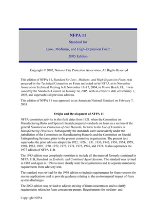
![Copyright NFPA
high-expansion foam systems have been included.
The 2005 edition reorganizes the requirements for low-, medium-, and high-expansion foam
to better incorporate the requirements of NFPA 11A.
Technical Committee on Foam
Christopher P. Hanauska, Chair
Hughes Associates, Inc., MD [SE]
Jean-Pierre Asselin, FireFlex Systems, Inc., Canada [M]
V. Frank Bateman, Kidde Fire Fighting, CA [M]
Gene E. Benzenberg, Alison Control Incorporated, NJ [M]
W. D. Cochran, Verde Environmental, TX [M]
Arthur R. Dooley, Jr., Dooley Tackaberry, Inc., TX [IM]
Rep. National Association of Fire Equipment Distributors
Robert A. Green, Public Service Electric & Gas Company, NJ [U]
Rep. Edison Electric Institute
Randall Hendricksen, ChemGuard, Incorporated, TX [M]
Eldon D. Jackson, The Viking Corporation, MI [M]
Rep. National Fire Sprinkler Association
Kevin P. Kuntz, Marsh USA Inc., NJ [I]
Eric LaVergne, Williams Fire and Hazard Control, TX [M]
Joan M. Leedy, Dyne Technologies, MN [IM]
Ronald Mahlman, The RJA Group, Inc., CA [SE]
Robert C. Merritt, FM Global, MA [I]
Rep. FM Global/FM Engineering & Research
Edward C. Norman, Aqueous Foam Technology, Inc., PA [SE]
Keith Olson, Tyco Suppression Systems, WI [M]
David W. Owen, ExxonMobil Corporation, VA [U]
Rep. American Petroleum Institute
Michael F. Pierson, CSC Advanced Marine, DC [SE]](data:image/gif;base64,R0lGODlhAQABAIAAAAAAAP///yH5BAEAAAAALAAAAAABAAEAAAIBRAA7)