lightening protection - Lightening arrester
•Download as DOCX, PDF•
4 likes•322 views

what is lightening? lightening wave shape? theories about lightening lightening protection lightening arrester MOV metal oxide varistors

Recommended
More Related Content
What's hot
What's hot (20)
Similar to lightening protection - Lightening arrester
Similar to lightening protection - Lightening arrester (20)
More from Kamran Hassan
More from Kamran Hassan (20)
Recently uploaded
Recently uploaded (20)
lightening protection - Lightening arrester
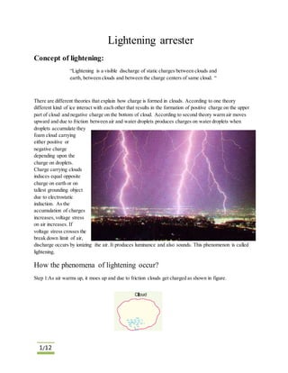
- 1. 1/12 Lightening arrester Concept of lightening: “Lightening is a visible discharge of static charges between clouds and earth, between clouds and between the charge centers of same cloud. “ There are different theories that explain how charge is formed in clouds. According to one theory different kind of ice interact with each other that results in the formation of positive charge on the upper part of cloud and negative charge on the bottom of cloud. According to second theory warm air moves upward and due to friction between air and water droplets produces charges on water droplets when droplets accumulate they foam cloud carrying either positive or negative charge depending upon the charge on droplets. Charge carrying clouds induces equal opposite charge on earth or on tallest grounding object due to electrostatic induction. As the accumulation of charges increases,voltage stress on air increases. If voltage stress crosses the break down limit of air, discharge occurs by ionizing the air. It produces luminance and also sounds. This phenomenon is called lightening. How the phenomena of lightening occur? Step 1:As air warms up, it moes up and due to friction clouds get charged as shown in figure.
- 2. 2/12 There may be more than one charged centers on a cloud as shown in figure. Clouds may get positive charged but 90 to 95% lightening strokes are due to negative charged strokes and only 5 to 10% are due to positively charged strokes. Step 2: due to electrostatic induction clouds create opposite charge on earth. Note: We will talk about only negative charges because mostly lightening strokes are due to negative charges. Step3: as the charged on the cloud increases,the potential difference between cloud and earth increases. If voltage exceeds the break down voltage of air, air will ionized and provide path to negative charges to move towards the earth as shown.
- 3. 3/12 Branches eliminates in mid air Earth Break down strength of air is 30KV/cm in atmospheric air and ~10KV/cm in the presence of moisture. First discharge called leader discharge also known as stepped leader because it moves down ward in discrete step of 50m to 100m. Stepped leader moves down ward with speed 5𝑥105 m/second and a current of some 100A. It may feelthat lightening stokes occur in one step but lightening occurs in steps and branches. These branches eliminates in the mid air while the main channel moves downward to the earth in zigzag manner. If we use a high sped camera and takes photographs of lightening it will look like following figure. If you note that stepped leader is not continuous but moves downward in jumps or in steps. In other words the ionization of intervene air is not continuous and instantaneous but discontinuous. also note that dart leader is continuous.
- 4. 4/12 It is not necessary that lightening always fall on earth if potential gradient E does not provides enough trust to charges then the main channel also disappear in the air as shown in figure. It has been seen that after first lightening stroke many other strokes occur that follow the same path as by the first stroke and they are brighter and none branched. The leader of Second and subsequent strokes are called “dart leader” because it moves 10 times faster than stepped leader. Dart leader are usually brighter and none branched. Dart leader Returned stroke
- 5. 5/12 Step 4: As stepped leader approaches towards earth,distance between negative charge centre and ground decreases due to which electric field intensity (E=V/d) increases. If any high earthed object (building, tower or any wire) is present and electric field intensity is high enough then upward positive discharge will occur that move upward by following the same path as stepped leader. It is called returned stroke as shown. Return stroke and stepped leader collides producing huge amount of lightening and sound. It neutralize the charge centre on the clouds such collision occur many times between dart stroke and return stroke producing large number of lightening flashes. This complete process of successive strokes is called “lightening flash” Return stroke moves with much high speed (50𝑥105 m/sec) and a current of some 250KA. Temperature of the lightening stroke channel is about 15000ºC to 20000ºC.
- 6. 6/12 During lightening air expands due to high temperature that pushes the nearby air causing storms. Lightening discharge may have current in the range of 10KA to 90KA. Lightening strokes from cloud to earth are very rare only 10% of lightening strokes. Majority of discharges take place between clouds. To find the energy of lightening stroke let assume that potential difference between cloud and earth is 95KV and total charge is 50columbs then as W=VxQ so energy =95000x50=4.75MJ=1.32KWh. Shielding wire damaged due to lightening flash is shown in figure.
- 7. 7/12 Lightening wave shape: A large number of experiments determine the Lightening wave shape. Lightening wave is characterized by two parts as shown in figure. One is wave front (from start point to it peak value) and other is wave tail (from its peak value to half of it peak value in decay side) Time to reach its peak value is denoted by 𝑡1and the time is to reach the half of its peak value in wave tail as 𝑡2 as shown in figure. 𝑡1 is ranges from 1 to 10µsec and 𝑡2 ranges from 50 to 1000µsec International standard lightening impulse voltage is define as 1.2/50µsec means 1.2µsec is the time to reach the peak value and 50µsec is the time to reach half of its peak value in the wave tail i.e.; 𝑡1 = 1.2µsec ±30% tolerance 𝑡2 = 50µsec±20% tolerance Standard peak value of lightening wave is 95KV i.e Em = 95KVas shown in figure. Lightening produces step rising voltage and the rate of rising of voltage is from 20KA/µsec to 100KA/µsec When such lightening falls on transmission line, produces two travelling waves that moves in both direction. Lightening strokes on overhead line: Lightening can fall on over head transmission line in two possible ways 1) Direct stroke 2) Indirect stroke Direct stroke: In direct stroke lightening directly fall on the over head transmission line producing two travelling waves moving towards the end poles of transmission line as shown. If there is lightening arrester at the end of transmission line, lightening wave will move to ground through tower without any damage provided that tower footing resistance is low. Critical flashover voltage(CFO) of self restoring insulator ( that can recover its insulation property after fault means no damage after flashover) is the voltage where insulator has 50% probability of flash over for a standard lightening wave i.e. 1.2/50µsec.CFO and
- 8. 8/12 BIL are used interchangeably but there is a slight difference between them. BIL is the voltage at which there is a 10% probability of flash over for standard lightening wave. Travelling wave Travelling wave of lightening Lightening may fall in other manner as shown. There are three clouds P,Q and R carrying charges positive, negative and positive respectively. If discharge occurs between cloud P and Q then charge on R will suddenly free and discharge rapidly to earth instead of transmission line. In this case lightening will fall on earth ignoring tall object.
- 9. 9/12 Indirect Stroke: In this case positively or negatively charged cloud induces opposite charge on over head line as shown in figure. Such case occur when lightening is near to over head line Positive charge cloud induces negative charge on line and positive charge at the end of transmission line. This trapped accumulated charge at the end of transmission line will leak to earth slowly through insulator. If charge on cloud discharges to another cloud or to earth, negative charge at the mid of transmission line is now free. This negative charge will flow towards end of transmission line in the foam of travelling wave. Most of the lightening faults are due to this reason. Lightening Protection on Overhead Line:
- 10. 10/12 To protect the overhead lines we use a wire called “ground wire” or “shielding wire”. It cross sectional area is half of the phase conductor. It is placed at the top of phase conductor. The reason of it is same that lightening will fall on tallest ground object which is shielding wire in this case. Shielding conductors are placed at the top of phase conductors in such a way that all lightening will fall on shielding conductor instead of phase conductors. Shielding conductors are grounded at each pole end. Note in case of overhead line, protection against lightening can also be provided by decreasing the footing resistance of the tower. If the footing resistance is high it will produce high voltage at the end of tower causing the line insulator to flashover or puncture causing the outage of line. It will produce arcing between shielding conductor and phase conductor. It can be removed by reenergizing the line. This phenomenon is called “backflashover”.it usually occurs when footing resistance is high. No of shielding conductors depends upon voltage level and level of protection. Lightening fall on the pole: Suppose that footing resistance of the tower is 20Ω and if lightening fall on the tower with current 22KA .some of the current will flow through shielding wire and remaining current will flow through tower. Suppose 1KA current flow through each shielding wire and remaining 20KA current will flow through tower then the voltage between tower and phase conductor will be V=20kAX20Ω=400Kv. This voltage will appear across insulator of line. If this voltage is greater than the flashover voltage of insulator, insulator flashover will occur. If the footing resistance is 40Ω then voltage of tower will be V=20kAx40Ω=800kV.so footing resistance greatly effect the voltage rise of tower and determines the level of protection against lightening. Tower resistance should be 20Ω or less than it. Groundingresistance
- 11. 11/12 Lightening fall on the mid of transmission line: 10000A Z=400Ω Suppose that lightening stroke current is about 10000A fall on a transmission line with surge impedance of Z=400Ω. Half current will flow in both direction so the voltage rise will be V=5000x400=2MV. Note here the voltage rise depends upon the surge impedance of the transmission line. Conclusion: So to avoid overvoltage due to lightening keep 1) Surge impedance low. 2) Footing resistance of tower low. 5000A5000A
- 12. 12/12 Lightening Arrester “Lightening arrester is an electrical protective device that is used to protect the electrical equipment from lightening by diverting the lightening surges to ground” Transformer without lightening arrestor when lightening falls transformer burns out When lighteing fall transformer is saved Transformer with lightening arrestor
- 13. 13/12 Modern types of surge arrester are made of metal oxide varistor (MOV). MOV are highly non linear resistors. Under normal voltage the resistance of MOV is very high and acts as an open circuit and draws current in miliamperes Wattage consumed by MOV is very small usually 0.05W/Kv One of the most important feature of MOV is that it resistance decreasesto few ohms instantaneously for high voltages and after voltage surge instantaneously return to its high value. Metal oxide varistors are zinc oxides. In MOV disk there are millions of conductive grains of zinc oxide that are separated by small distance as shown. MOV disk Doping material Zinc grains MOV disks Lightening arrestor
- 14. 14/12 Current path during lightening These gaps between zinc conductive grains behave like switches that activates when lightening falls. Spark gap was one of the oldest devices used to protect equipment against lightening. The principle of gap type lightening arrester was same as that of MOV. Under normal condition gap act as open circuit. When high voltage surge occur, air between gap ionizes causes gap to short circuit. But the basic problem with this lightening arrestor was that after the surge has removed but gap is still short circuited due to ionized air because once the air is ionized very small voltage is required to keep the ionized path alive. So we have to operate the circuit breaker. Later modification was made in gap arrester by inserting non linear resistance in series with spark gap. Resistance of non linear resistance increases to a high value when voltage decreases so current becomes very small that makes the gap open again. Arrester must be placed as closed as possible to the equipment to protect
- 15. 15/12 Lightening arrestor. Fuses of transformer Lightening arrestor Transformer Lightening arrestor Transmission line
- 16. 16/12 Every two terminal device must be protected by lightening arrestor like regulators, reclosure, isolators or switches. Arrestor across recloser is very important. Recloser opens when lightening fault occur so surge reaches open point will double so lightening arrester must be there for the safety of recloser. Usually capacitor banks are not protected with surge arrestor because capacitor also act as surge arrestor but direct lightening sometime fail capacitor to operate. Surge arrestor does not stop or absorb the lightening surges. It just divert the lightening surges to ground.