This is the Highly Detailed factory service repair manual for theCASE CX36B MINI EXCAVATOR, this Service Manual has detailed illustrations as well as step by step instructions,It is 100 percents complete and intact. they are specifically written for the do-it-yourself-er as well as the experienced mechanic.CASE CX36B MINI EXCAVATOR Service Repair Workshop Manual provides step-by-step instructions based on the complete dis-assembly of the machine. It is this level of detail, along with hundreds of photos and illustrations, that guide the reader through each service and repair procedure. Complete download comes in pdf format which can work under all PC based windows operating system and Mac also, All pages are printable. Using this repair manual is an inexpensive way to keep your vehicle working properly.
Service Repair Manual Covers:
Specifications
Attachment Dimensions
Tools
Standard Maintenance Time Table
Maintenance Standards and Test Procedures
Hydraulic System
Electrical System
Components System
Whole Disassembling and Assembling
Attachments
Upper Slewing Structure
Travel System
Hydraulic System
Electrical System
Engine
Supporting Data
Applicable Machines
Electrical and Hydraulic Schematic Diagram
File Format: PDF
Compatible: All Versions of Windows & Mac
Language: English
Requirements: Adobe PDF Reader
NO waiting, Buy from responsible seller and get INSTANT DOWNLOAD, Without wasting your hard-owned money on uncertainty or surprise! All pages are is great to haveCASE CX36B MINI EXCAVATOR Service Repair Workshop Manual.
Looking for some other Service Repair Manual,please check:
https://www.aservicemanualpdf.com/
Thanks for visiting!
Exploring the Heart of Alberta: A Journey from Calgary to Edmonton
CASE CX36B MINI EXCAVATOR Service Repair Manual
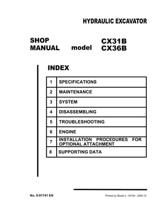
1. CX31B
CX36B
1 SPECIFICATIONS
2 MAINTENANCE
3 SYSTEM
4 DISASSEMBLING
5 TROUBLESHOOTING
6 ENGINE
7 INSTALLATION PROCEDURES FOR
OPTIONAL ATTACHMENT
8 SUPPORTING DATA
SHOP
MANUAL
INDEX
HYDRAULIC EXCAVATOR
No. 9-91741 EN Printed by Studio ti - 53104 - 2004.12
model
3. SAFETY PRECAUTIONS
0-2
GENERAL SAFETY INFORMATION
SWARNING
Do not operate or perform any maintenance on this
machine until all instructions found in the OPERA-
TION & MAINTENANCE MANUAL have been thor-
oughly read and understood.
Improper operation or maintenance of this machine
may cause accidents and could result in serious in-
jury or death.
Always keep the manual in storage.
If it is missing or damaged, place an order with an
authorized our Distributor for a replacement.
If you have any questions, please consult an au-
thorized our Distributor.
(1) Most accidents, which occur during operation, are
due to neglect of precautionary measures and safe-
ty rules. Sufficient care should be taken to avoid
these accidents. Erroneous operation, lubrication
or maintenance services are very dangerous and
may cause injury or death of personnel. Therefore
all precautionary measures, NOTES, DANGERS,
WARNINGS and CAUTIONS contained in the man-
ual and on the machine should be read and under-
stood by all personnel before starting any work with
or on the machine.
(2) Operation, inspection, and maintenance should be
carefully carried out, and safety must be given the
first priority. Messages of safety are indicated with
marks. The safety information contained in the
manual is intended only to supplement safety
codes, insurance requirements, local laws, rules
and regulations.
(3) Messages of safety appear in the manual and on
the machine: All messages of safety are identified
by either word of "DANGER", "WARNING" and
"CAUTION".
1) DANGER- Indicates an imminently hazardous
situation which, if not avoided, will result in
death or serious injury and is represented as
follows:
SDANGER
2) WARNING- Indicates a potentially hazardous
situation which, if not avoided, could result in
death or serious injury and is represented as
follows:
SWARNING
3) CAUTION- Indicates a potentially hazardous
situation which, if not avoided, may result in mi-
nor or moderate injury. It may also be used to
alert against possible damage to the machine
and its components and is represented as fol-
lows:
SCAUTION
(4) It is very difficult to forecast every danger that may
occur during operation. However, safety can be en-
sured by fully understanding proper operating pro-
cedures for this machine according to methods
recommended by Manufacturer.
(5) While operating the machine, be sure to perform
work with great care, so as not to damage the ma-
chine, or allow accidents to occur.
(6) Continue studying the manual until all Safety, Oper-
ation and Maintenance procedures are completely
understood by all persons working with the ma-
chine.
4. SAFETY PRECAUTIONS
0-3
SAFETY PRECAUTIONS
SWARNING
The proper and safe lubrication and maintenance
for this machine, recommended by Manufacturer,
are outlined in the OPERATOR’S MANUAL for the
machine.
Improper performance of lubrication or mainte-
nance procedures are dangerous and could result
in injury or death. Read and understand the MAN-
UAL before performing any lubrication or mainte-
nance.
The serviceman or mechanic may be unfamiliar
with many of the systems on this machine. This
makes it important to use caution when perform-
ing service work. A knowledge of the system and or
components is important before the removal or dis-
assembly of any component.
Because of the size of some of the machine compo-
nents, the serviceman or mechanic should check the
weights noted in this manual. Use proper lifting proce-
dures when removing any components. Weight of com-
ponents table is shown in the section:
SPECIFICATIONS.
The following is a list of basic precautions that must al-
ways be observed.
(1) Read and understand all Warning plates and de-
cal on the machine before Operating, Maintaining
or Repairing this machine.
(2) Always wear protective glasses and protective
shoes when working around machines. In partic-
ular, wear protective glasses when using ham-
mers, punches or drifts on any part of the machine
or attachments. Use welders gloves, hood/gog-
gles, apron and the protective clothing appropriate
to the welding job being performed. Do not wear
loose fitting or torn clothing. Remove all rings from
fingers, loose jewelry, confine long hair and loose
clothing before working on this machinery.
(3) Disconnect the battery and hang a "Do Not Oper-
ate" tag in the Operators Compartment. Remove
ignition keys.
(4) If possible, make all repairs with the machine
parked on a level, hard surface. Block the ma-
chine so it does not roll while working on or under
the machine. Hang a "Do Not Operate" tag in the
Operators Compartment.
(5) Do not work on any machine that is supported only
by lift, jacks or a hoist. Always use blocks or jack
stands, capable of supporting the machine, before
performing any disassembly.
SWARNING
Do not operate this machine unless you have
read and understand the instructions in the
OPERATOR’S MANUAL. Improper machine
operation is dangerous and could result in in-
jury or death.
(6) Relieve all pressure in air, oil or water systems be-
fore any lines, fittings or related items are discon-
nected or removed. Always make sure all raised
components are blocked correctly and be alert for
possible pressure when disconnecting any device
from a system that utilizes pressure.
(7) Lower the bucket, dozer, or other attachments to
the ground before performing any work on the ma-
chine. If this cannot be done, make sure the buck-
et, dozer, ripper or other attachment is blocked
correctly to prevent it from dropping unexpectedly.
(8) Use steps and grab handles when mounting or
dismounting a machine. Clean any mud or debris
from steps, walkways or work platforms before us-
ing. Always face to the machine when using
steps, ladders and walkways. When it is not pos-
sible to use the designed access system, provide
ladders, scaffolds, or work platforms to perform
safe repair operations.
(9) To avoid back injury, use a hoist when lifting com-
ponents which weigh 20 kg (45 lbs) or more. Make
sure all chains, hooks, slings, etc., are in good
condition and are the correct capacity. Be sure
hooks are positioned correctly. Lifting eyes are
not to be side loaded during a lifting operation.
(10) To avoid burns, be alert for hot parts on machines
which have just been stopped and hot fluids in
lines, tubes and compartments.
(11) Be careful when removing cover plates. Gradually
back off the last two capscrews or nuts located at
opposite ends of the cover or device and carefully
pry cover loose to relieve any spring or other pres-
sure, before removing the last two capscrews or
nuts completely.
(12) Be careful when removing filler caps, breathers
and plugs on the machine. Hold a rag over the
cap or plug to prevent being sprayed or splashed
by liquids under pressure. The danger is even
greater if the machine has just been stopped be-
cause fluids can be hot.
(13) Always use the proper tools that are in good con-
dition and that are suited for the job at hand. Be
5. SAFETY PRECAUTIONS
0-4
sure you understand how to use them before per-
forming any service work.
(14) Reinstall all fasteners with the same part number.
Do not use a lesser quality fastener if replace-
ments are necessary.
(15) Repairs which require welding should be per-
formed only with the benefit of the appropriate ref-
erence information and by personnel adequately
trained and knowledgeable in welding proce-
dures. Determine type of metal being welded and
select correct welding procedure and electrodes,
rods or wire to provide a weld metal strength
equivalent at least to that of the parent metal.
Make sure to disconnect battery before any weld-
ing procedures are attempted.
(16) Do not damage wiring during removal operations.
Reinstall the wiring so it is not damaged nor will be
damaged in operation of the machine by contact-
ing sharp corners, or by rubbing against some ob-
ject or hot surface. Do not connect wiring to a line
containing fluid.
(17) Be sure all protective devices including guards
and shields are properly installed and functioning
correctly before starting a repair. If a guard or
shield must be removed to perform the repair
work, use extra caution and replace the guard or
shield after repair is completed.
(18) The maintenance and repair work while holding
the bucket raised is dangerous due to the possibil-
ity of a falling attachment. Don’t fail to lower the at-
tachment and place the bucket to the ground be-
fore starting the work.
(19) Loose or damaged fuel, lubricant and hydraulic
lines, tubes and hoses can cause fires. Do not
bend or strike high pressure lines or install ones
which have been bent or damaged. Inspect lines,
tubes and hoses carefully. Do not check for leaks
with your hands. Very small (pinhole) leaks can re-
sult in a high velocity oil stream that will be invisi-
ble close to the hose. This oil can penetrate the
skin and cause personal injury. Use card-board or
paper to locate pinhole leaks.
(20) Tighten connections to the correct torque. Make
sure that all heat shields, clamps and guards are
installed correctly to avoid excessive heat, vibra-
tion or rubbing against other parts during opera-
tion. Shields that protect against oil spray onto hot
exhaust components in event of a line, tube or
seal failure must be installed correctly.
(21) Do not operate a machine if any rotating part is
damaged or contacts any other part during opera-
tion. Any high speed rotating component that has
been damaged or altered should be checked for
balance before reusing.
(22) Be careful when servicing or separating the tracks
(crawlers). Chips can fly when removing or install-
ing a track (crawlers) pin. Wear safety glasses and
long sleeve protective clothing. Tracks (crawlers)
can unroll very quickly when separated. Keep
away from front and rear of machine. The ma-
chine can move unexpectedly when both tracks
(crawlers) are disengaged from the sprockets.
Block the machine to prevent it from moving.
6. SAFETY PRECAUTIONS
0-5
INDEX CX31B
CX36B
Title Index
No.
SPECIFICATIONS
OUTLINE 1
SPECIFICATIONS 2
ATTACHMENT DIMENSIONS 3
MAINTENANCE
TOOLS 11
STANDARD MAINTENANCE TIME TABLE 12
MAINTENANCE STANDARDS AND TEST PROCEDURES 13
SYSTEM
HYDRAULIC SYSTEM 22
ELECTRICAL SYSTEM 23
COMPONENTS SYSTEM 24
DISASSEMBLING
WHOLE DISASSEMBLING & ASSEMBLING 31
ATTACHMENTS 32
UPPER SLEWING STRUCTURE 33
TRAVEL SYSTEM 34
TROUBLESHOOTING
HYDRAULIC SYSTEM 42
ELECTRICAL SYSTEM 43
ENGINE 44
E/G
ENGINE 51
OPT.DATA
SUPPORTING DATA 71
APPLICABLE MACHINES
7. 1. OUTLINE
TABLE OF CONTENTS
1.1 GENERAL PRECAUTIONS FOR REPAIRS .....................................................1-3
1.1.1 PREPARATION BEFORE DISASSEMBLING ..............................................1-3
1.1.2 SAFETY IN DISASSEMBLING AND ASSEMBLING ....................................1-3
1.1.3 DISASSEMBLING AND ASSEMBLING HYDRAULIC EQUIPMENT ............1-3
1.1.4 ELECTRICAL EQUIPMENT ..........................................................................1-4
1.1.5 HYDRAULIC PARTS .....................................................................................1-5
1.1.6 WELDING REPAIR .......................................................................................1-5
1.1.7 ENVIRONMENTAL MEASURE .....................................................................1-5
1.2 INTERNATIONAL UNIT CONVERSION SYSTEM ............................................1-6
9. 1. OUTLINE
1-3
1.1 GENERAL PRECAUTIONS FOR
REPAIRS
1.1.1 PREPARATION BEFORE DISASSEM-
BLING
(1) Understanding operating procedure
Read OPERATION & MAINTENANCE MANUAL
carefully to understand the operating procedure.
(2) Cleaning machines
Remove soil, mud, and dust from the machine be-
fore carrying it into the service shop to prevent loss
of work efficiency, damage of parts, and difficulty in
rust prevention and dust protection while reassem-
bling.
(3) Inspecting machines
Identify the parts to be disassembled before start-
ing work, determine the disassembling procedure
by yourself considering the workshop situations
etc., and request procurement of necessary parts in
advance.
(4) Recording
Record the following items for communication and
prevention of recurring malfunction.
1) Inspection date and place.
2) Model name, applicable machine number, and
hour meter read.
3) Trouble condition, place and cause.
4) Visible oil leakage, water leakage and damage.
5) Clogging of filters, oil level, oil quality, oil con-
tamination and loosening of connections.
6) Result of consideration if any problem exists
based on the operation rate per month calculat-
ed from hour meter indication after the last in-
spection date.
(5) Arrangement and cleaning in service shop
1) Tools required for repair work.
2) Prepare space to place the disassembled parts.
3) Prepare oil containers for draining oil etc.
1.1.2 SAFETY IN DISASSEMBLING AND AS-
SEMBLING
(1) Wear appropriate clothes with long sleeves, safety
shoes, safety helmet and protective glasses.
(2) Suspend warning tag "DO NOT OPERATE" from
the doorknob or the operating lever, and have a
preliminary meeting before starting work.
(3) Stop the engine before starting inspection and
maintenance to prevent the operator being caught
in machine.
(4) Identify the location of a first-aid kit and a fire extin-
guisher, and also where to make contact in a state
of emergency.
(5) Choose a hard, level and safe place, and place the
attachment on the ground securely.
(6) Use a lifter such as a crane to remove heavy parts
(20 kg [45 lbs] or more) from the machine.
(7) Use proper tools, and replace or repair defective
tools.
(8) Support the machine and attachment with supports
or blocks if the work is performed in the lifted condi-
tion.
1.1.3 DISASSEMBLING AND ASSEMBLING HY-
DRAULIC EQUIPMENT
(1) Removing hydraulic equipment
1) Before disconnecting pipes, release the hy-
draulic pressure of the system, or open the re-
turn side cover and take out the filter.
2) Carefully drain oil of the removed pipes into a
containers without spilling on the floor.
3) Apply plugs or caps on the pipe ends to avoid
oil spillage and dust intrusion.
4) Clean off the external surface of the equipment
before disassembling, and drain hydraulic and
gear oil before placing it on the workbench.
(2) Disassembling hydraulic equipment
1) Do not disassemble, reassemble or modify the
hydraulic equipment without the permission of
the manufacturer, who is not responsible for the
performance and function of the product after
modification.
2) When disassembling and reassembling for un-
avoidable reason, refer the work to qualified
personnel who have the specific knowledge or
completed the parts service training.
3) Provide matching marks to facilitate reassem-
bling work.
4) Before starting the work, read the manual of
disassembling procedure, if it is provided, and
decide whether the work can be performed by
yourself.
10. 1. OUTLINE
1-4
5) Use the special jig and tools without fail if they
are specified.
6) If it is hard to remove a part according to the
procedure, do not try it by force but investigate
the cause.
7) Place the removed parts in order and attach
tags to facilitate the reassembling.
8) Note the location and quantity of parts com-
monly applied to multiple locations.
(3) Inspecting parts
1) Ensure that the disassembled parts are free
from seizure, interference and uneven contact.
2) Measure and record wear condition of parts
and clearance.
3) If the problem is found in a part, repair or re-
place it with a new one.
(4) Reassembling hydraulic equipment
1) Turn ON the ventilation fan or open windows to
maintain good ventilation prior to starting the
cleaning of parts.
2) Perform rough and finish cleaning before as-
sembling.
3) Remove washing oil by air and apply clean hy-
draulic or gear oil for assembling.
4) Always replace the removed O-rings, backup
rings and oil seals with new ones by applying
grease in advance.
5) Remove dirt and moisture from and perform de-
greasing on the surface where liquid gasket to
be applied.
6) Remove rust preventive agent from the new
parts before use.
7) Fit bearings, bushings and oil seals using spe-
cial jigs.
8) Assemble the parts utilizing matching marks.
9) Ensure all the parts are completely assembled
after the work.
(5) Installing hydraulic equipment
1) Ensure hydraulic oil and lubricant are properly
supplied.
2) Perform air bleeding when:
1. Hydraulic oil changed
2. Parts of suction side piping replaced
3. Hydraulic pump installed
4. Slewing motor installed
5. Travel motor installed
6. Hydraulic cylinder installed
SWARNING
Operation of the hydraulic equipment with-
out filling hydraulic oil or lubricant or with-
out performing air bleeding will result in
damage to the equipment.
3) Perform air bleeding of the hydraulic pump and
slewing motor after loosening the upper drain
plug, starting the engine and keep it in low idle
condition.
Complete the air bleeding when seeping of hy-
draulic oil is recognized, and tightly plug.
4) Perform air bleeding of the travel motor and the
hydraulic cylinders by running the engine for
more than 5 minutes at low speed without load.
SWARNING
Do not allow the hydraulic cylinder to bot-
tom on the stroke end just after the mainte-
nance.
5) Perform air bleeding of pilot line by performing
a series of digging, slewing and travel.
6) Check hydraulic oil level after placing the at-
tachment to the oil check position, and replen-
ish oil if necessary.
1.1.4 ELECTRICAL EQUIPMENT
(1) Do not disassemble electrical equipment.
(2) Handle it carefully not to drop and give a shock.
(3) Turn the key OFF prior to connecting and discon-
necting work.
(4) Disconnect the connector by holding it and press-
ing the lock. Do not pull the wire to apply force to the
caulking portion.
(5) Connect the connector and ensure it is completely
locked.
(6) Turn the key OFF prior to touching the terminal of
starter or generator.
(7) Remove the ground (earth) terminal of battery
when handling tools around the battery or its relay.
(8) Do not splash water on the electrical equipment
and connectors during machine washing.
(9) Check for moisture adhesion inside the waterproof
connector after pulling it out, since it is hard to re-
move moisture from the connector.
11. 1. OUTLINE
1-5
If moisture adhesion is found, dry it completely be-
fore the connection.
SWARNING
Battery electrolyte is hazardous.
Battery electrolyte is dilute sulfuric acid. Exposure
of skin or eyes to this liquid will cause burning or
loss of eyesight.
If the exposure occurs, take the following emergen-
cy measures and seek the advice of a medical spe-
cialist.
• When skin exposed:
Wash with water and soap sufficiently.
• When eyes exposed:
Immediately wash away with city water continu-
ously for more than 10 minutes.
• When a large amount of the liquid flows out:
Neutralize with sodium bicarbonate or wash
away with city water.
• When swallowed:
Drink a large amount of milk or water.
• When clothes exposed:
Immediately undress and wash.
1.1.5 HYDRAULIC PARTS
(1) O-ring
• Ensure O-rings have elasticity and are not dam-
aged before use.
• Use the appropriate O-rings. O-rings are made
of various kinds of materials having different
hardness to apply to a variety of parts, such as
the part for moving or fixed portion, subjected to
high pressure, and exposed to corrosive fluid,
even if the size is same.
• Fit the O-rings without distortion and bend.
• Always handle floating seals as a pair.
(2) Flexible hose (F hose)
• Use the appropriate parts. Different parts are
used depending on the working pressure even
the size of fitting and the total length of the hose
is same.
• Tighten the fitting at the specified torque.
Ensure no kink, tension, interference nor oil
leakage is recognized.
1.1.6 WELDING REPAIR
(1) Refer repair welding to qualified personnel accord-
ing to the appropriate procedure.
(2) Disconnect the ground (earth) cable of the battery
before starting the repair.
Failure to do so will cause damage to the electrical
equipment.
(3) Move away the articles in advance that may cause
fire if exposed to sparks.
(4) Before starting the repair of the attachment, do not
fail to cover the plated surface of the piston rod with
flameproof sheet to prevent it from being exposed
to sparks.
1.1.7 ENVIRONMENTAL MEASURE
(1) Run the engine at the place that is sufficiently ven-
tilated.
(2) Industrial waste disposal
Dispose of the following parts according to the rel-
evant regulations:
Waste oil and waste container
Battery
(3) Precautions for handling hydraulic oil
Exposure of eyes to hydraulic oil will cause inflam-
mation. Wear protective glasses before handling to
avoid an accident. If an eye is exposed to the oil,
take the following emergency measures:
• When an eye exposed:
Immediately wash away with city water suffi-
ciently till stimulative feeling vanishes.
• When swallowed:
Do not let vomit, and receive medical treatment
immediately.
• When skin exposed:
Wash with water and soap sufficiently.
(4) Others
Use replacement parts and lubricants authorized as
the genuine parts.
12. 1. OUTLINE
1-6
1.2 INTERNATIONAL UNIT CON-
VERSION SYSTEM
(Based on MARKS’ STANDARD
HANDBOOK FOR MECHANI-
CAL ENGINEERS)
Introduction
Although this manual includes International System of
Unit and Foot-Pound System of Units, if you need SI
unit, refer to the following international system of units.
Given hereinafter is an excerpt of the units that are re-
lated to this manual.
1. Etymology of SI Unites
French: Le Systeme International d’ Unites
English: International System of Units
2. Construction of SI Unit System
(1) Base units
(2) Supplementary units
(3) Derived Units
(4) Derived Units bearing Peculiar Designations
Table 1-1
QUANTITY UNIT SYMBOL
Length meter m
Mass kilogram kg
Time second s
Electric current ampere A
Thermodynamic
temperature
kelvin K
Amount of
substance
mol mol
Luminous
intensity
candela cd
Table 1-2
QUANTITY UNIT SYMBOL
Plane angle radian rad
Solid angle steradian sr
Base units
Table 1-1
Derived units
of base units
Table 1-2
Supplemen-
tary units
Table 1-2
Derived
units
Derived units
bearing peculiar
designations
Table 1-4
Prefixes of SI
(n-th power of 10, where n is an integer)
Table 1-5
SI units
SI unit
system
Table 1-3
QUANTITY UNIT SYMBOL
Area square meter m2
Volume cubic meter m3
Velocity meter per second m/s
Acceleration meter per second squared m/s2
Density kilogram per cubic meter kg/m3
Table 1-4
QUANTITY UNIT SYMBOL FORMULA
Frequency hertz Hz 1/s
Force newton N kg • m/s 2
Pressure and
Stress
pascal Pa N/m2
Energy, Work
and Quantityof
heat
joule J N•m
Power watt W J/s
Quantity of
electricity
coulomb C A•s
Electric
potential
difference,
Voltage, and
Electromotive
force
volt V W/A
Quantity of
static
electricity and
Electric
capacitance
farad F C/V
Electric
resistance
ohm V/A
Celsius
temperature
celsius
degree or
degree
C (t+273.15)K
Illuminance lux lx lm/m2
13. 1. OUTLINE
1-7
(5) Prefixes of SI
(6) Unit Conversion
*1 Units that are allowed to use.
Table 1-5
PREFIX SYMBOL MULTIPLICATION FACTORS
giga G 109
mega M 106
kilo k 103
hecto h 102
deca da 10
deci d 10–1
centi c 10–2
milli m 10–3
micro µ 10–6
nano n 10–9
pico p 10–12
Table 1-6
QUANTITY Gravitationa
l
SI CONVERSION
FACTOR
Mass kg kg
Force kgf N 1 kgf = 9.807 N
Torque kgf•m N•m kgf•m = 9.807 N•m
Pressure kgf/cm2 MPa 1 kgf/cm2 = 0.09807 MPa
Motive
Power
PS kW 1 PS = 0.7355 kW
Revolution rpm min–1
r/min *1
14. 2. SPECIFICATIONS
TABLE OF CONTENTS
2.1 COMPONENTS NAME .....................................................................................2-3
2.2 MACHINE DIMENSIONS ..................................................................................2-4
2.3 SPECIFICATIONS AND PERFORMANCE .......................................................2-6
2.4 MACHINE & COMPONENTS WEIGHT (DRY) .................................................2-7
2.5 TRANSPORTATION .........................................................................................2-9
2.6 TYPE OF CRAWLER SHOES ........................................................................2-11
2.7 TYPE OF BUCKET .........................................................................................2-11
2.8 ENGINE SPECIFICATIONS ............................................................................2-13
2.8.1 SPECIFICATIONS ......................................................................................2-13
2.8.2 ENGINE PERFORMANCE CURVE ............................................................2-14
22. 2. SPECIFICATIONS
2-9
2.5 TRANSPORTATION
(1) LOADING MACHINE ON A TRAILER
1) Keep trailer bed clean. Put chocks against truck wheels.
2) Use a ramp or loading deck. Ramps must be strong enough, have a low angle, and correct height. Load and
unload machine on a level surface.
3) Travel machine onto ramps slowly. Center the machine over the trailer.
4) Lower all attachment.
5) Stop engine. Remove key from switch.
SWARNING
Do not put chains over or against hydraulic lines or hoses.
6) Fasten machine to trailer with chains or cables.
During transportation, the bucket or attachments may hit the canopy or the cab. Therefore, set the machine in
the transporting position by observing following points:
1. Extend the bucket cylinder fully.
2. Extend the dipper cylinder fully.
3. Lower the boom.
4. If machine cannot be transported with dipper cylinder fully extended, remove bucket or attachment and ex-
tend dipper cylinder.
(2) TRANSPORTATION DIMENSION AND WEIGHT OF ATTACHMENT
1) BOOM WITH DIPPER CYLINDER
2) DIPPER & BUCKET
Model CX31B CX36B
L × H × W
mm (ft•in)
2390 × 870 × 320
(7’10.1") (2’10.2") (12.6")
2590 × 810 × 320
(8’6.0") (2’7.9") (12.6")
Weight w/dipper cyl. kg
(lb)
163 (360) 184 (405)
Model CX31B CX36B
L × H × W
mm (ft•in)
2190 × 450 × 500
(7’2.2") (17.7") (19.7")
2360 × 450 ×600
(7’8.9") (17.7") (1’11.6")
Weight kg (lb) 198 (435) 219 (485)
L
H
L
H
23. 2. SPECIFICATIONS
2-10
3) DIPPER
4) BUCKET
5) DOZER
w/o cylinder weight
Model CX31B CX36B
L × H × W
mm (ft•in)
1520 × 430 × 280
(4’11.8") (16.9") (11.0")
1690 × 430 ×280
(5’6.5") (16.9") (11.0")
Weight kg (lb) 101 (225) 123 (270)
Model CX31B CX36B
Heaped capacity
m3
(cu•yd)
0.09 (0.118) 0.11 (0.144)
L × H × W
mm (in)
670 × 620 × 500
(2’2.4") (2’0.4") (19.7")
670 × 620 × 600
(2’2.4") (2’0.4") (1’11.6")
Weight kg (lb) 81 (180) 89 (196)
Model CX31B CX36B
L × H × W
mm (in)
1230 × 330 × 1550
(4’0.4") (13.0") (5’1.0")
1280 × 330 × 1700
(4’2.4") (13.0") (5’6.9")
Weight kg (lb) 142 (315) 150 (330)
L
H
L
H
L
H
25. 2. SPECIFICATIONS
2-12
SWARNING
◆ The buckets with this length, during left dipper slewing higher than 1 m from ground, can interfere with the cabin.
For a safe use, consult the Dealer and ask for left slewing limiter of the dipper support.
●: Width with lateral cutter
❍: Width without lateral cutter
: Generic digging
for digging and sand loading operations, gravel, clay, earth in general, etc..
The specific weight of the material should not be higher than 1400 kg/m3
.
■: Digging for light applications for operations of digging,sand loading/unloading of gravel, clay, earth in friabile and
dry state, ditch cleaning, etc.
26. 2. SPECIFICATIONS
2-13
2.8 ENGINE SPECIFICATIONS
2.8.1 SPECIFICATIONS
Model CX31B, CX36B
Engine Model 3TNV88-PYB
Type Vertical, 4-cycle water-cooled diesel engine
No. of cylinders - Bore × Stroke 3 - 88 mm (3.46 in) × 90 mm (3.54 in)
Total displacement 1.642 liter (100 cu•in)
Compression ratio 19.1
Rated output 21.2 kW (28.8 PS) at 2400 rpm
Maximum torque 99 ~ 108 N•m (73.1 ~ 79.6 lbf•ft) at 1400 rpm
Low idling 1250 ± 25 rpm
High idling 2590 ± 25 rpm
Fuel consumption rate Less than 180 g / PS•h
Allowable tilting angles Continuous; 30° for all direction
Rotating direction Counterclockwise as seen from flywheel side
Firing order 1-3-2-1
Fuel injection timing (FID, b.T.D.C.) 14 ± 1°
Fuel injection pressure 200 kg / cm2
(2840 psi)
Valve action
Open Close
Intake valve b.T.D.C. 15 ± 5° a.B.D.C. 45 ± 5°
Exhaust valve b.T.D.C. 56 ± 5° a.B.D.C. 18 ± 5°
Valve clearance
Intake valve 0.2 mm (0.008 in) in cold condition
Exhaust valve 0.2 mm (0.008 in) in cold condition
Thermostat action Start 71 ± 1.5 °C (160 ± 3 °F) / Full open 85 °C (185 °F)
Compression pressure 3.43 ± 0.1 MPa (500 ± 14 psi) at 250 rpm
Lubrication oil pressure 0.44 MPa (64 psi) at 2300 rpm
Dimensions L × W × H 585 × 521 × 648 mm (23.0 × 20.5 × 25.5 in)
Dry weight 155 kg (342 lb)
Governor Mechanical centrifugal governor (All speed type)
Fuel filtration cartridge type paper filter
Lubrication system Forced lubrication with trochoid pump
Cooling system Liquid cooling / Radiator
Starter capacity 12 V × 1.7 kW
Generator capacity 12 V × 50 A
Starting aid Air heater (12 V - 400 W)
Cooling water capacity: Max / Engine 4.0 / 2.0 liter (1.06 / 0.53 gal)
Engine oil volume: Max / Effective 6.7 / 2.8 liter (1.77 / 0.74 gal)
27. 2. SPECIFICATIONS
2-14
2.8.2 ENGINE PERFORMANCE CURVE
CX31B, CX36B
Model: 3TNV88A-PYB
Rated Output: 21.2 kW / 2400 min-1
(28.8 PS / 2,400 rpm)
F
Fuel consumption volume = X P X α
ρ X 1000
245
= X 21.2 X α
0.835 X 1000
= 6.21 α
Sd
GT
T
PS
F
[ T ]
[Sd]
[ F ]
[PS]
[GT]
min 1
{rpm}
(92)
(74)
(55)
(37)
(18)
F. Fuel consumption rate (g/kwh)
P. Shaft output (kw)
ρ. Specific gravity
α. Standard load factory (0.60 ~ 0.70)
Fuel consumption in normal operation; 3.73 ~ 4.35 L/h
(load factor: (0.60 ~ 0.70))
T. Shaft torque
F. Fuel consumption rate
PS.Power output
GT. Exhaust temperature
Sd. Smoke: Bosch
30. 3. ATTACHMENT DIMENSIONS
3-3
3.1 BOOM
3.1.1 BOOM DIMENSIONAL DRAWINGS
Fig. 3-1 Boom Dimensional Drawings
Table 3-1
Unit: mm (ft-in)
No. NAME
DIMENSIONS
CX31B CX36B
A Boom length 2300 (7’6.55") 2500 (8’2.43")
B Distance between pins of boss R1217.5 (3’11.93") R1210 (3’11.64")
C Distance between pins of bracket R1130.5 (3’8.51") R1157 (3’9.55")
D Height of boom cylinder rod pin 420.5 (1’4.56") 385.5 (1’3.18")
E Height of Dipper cylinder (head side) pin 764 (2’6.08") 708 (2’3.87")
F Boom width 178 (7.01") ←
G
Inner width of bracket for boom cylinder (rod side) mount-
ing
61 (2.40") ←
H Boom end inner width 150 (5.91") ←
J Boom end outer width 235 (9.25") ←
K Inner width of bracket for dipper cylinder (head side) 61 (2.40") ←
d1
Boom pin dia.
[Bushing outer dia.]
ø45 (1.77")
[ø55 (2.17")]
←
d2 Boom cylinder (rod side) pin dia. ø45 (1.77") ←
d3 Pin dia. of dipper end ø45 (1.77") ←
d4 Dipper cylinder (head side) pin dia. ø45 (1.77") ←
31. 3. ATTACHMENT DIMENSIONS
3-4
3.1.2 BOOM MAINTENANCE STANDARDS
(1) Clearance of pin and bushing on boom section
Fig. 3-2 Clearance of pin and bushing on boom section
(Note)
• The tolerance for bushing inside diameter means the dimension after fitting of it into place.
• The part number for pins may be changed owing to improvement, use them only for reference.
Table 3-2
Unit: mm (in)
Pos. Item
Standard dimensions Clearance
Remedy
Pin dia.
Tolerance
on pin dia.
Tolerance
on bushing
bore dia.
Standard
value
Standard
value for
repair
Servicea-
bility limit
A Boom foot
ø45
(1.7717)
–0.02
–0.05
(-0.0008)
(-0.0020)
+0.10
+0.05
(+0.0039)
(+0.0020)
0.07~
0.15
(0.0028~
0.0059)
0.7
(0.028)
1.0
(0.039)
Replace
bushing
or pin
B
Boom cylinder
(Head side)
–0.02
–0.08
(-0.0008)
(-0.0031)
+0.12
+0.06
(+0.0047)
(+0.0024)
0.08~
0.20
(0.0031~
0.0079)
C
Boom cylinder
(Rod side)
–0.02
–0.05
(-0.0008)
(-0.0020)
+0.13
+0.07
(+0.0051)
(+0.0028)
0.09~
0.23
(0.0035~
0.0091)
D
Dipper cylinder
(Head side)
32. 3. ATTACHMENT DIMENSIONS
3-5
(2) Clearance in thrust direction on boom and cylinder installation section
Fig. 3-3 Clearance in thrust direction on boom section
33. 3. ATTACHMENT DIMENSIONS
3-6
Table 3-3
Unit: mm (in)
Sec. Item
Standard dimen-
sions
Clearance X adjusted with shim
(total of both sides)
Remedy
Pin length
No. Dimensions
Standard
value
Standard
value for
repair
Serviceabil-
ity limit
No. Dimensions
A-A Boom
Boom
L1
178
(7.008 )
0.2~0.6
(0.008~
0.024)
1.0
(0.039)
1.5
(0.059)
Adjust-
ed with
shim
PL1
297
(11.69)
Swing
bracket
178
(7.008 )
B-B
Boom cylinder
(Head side)
Boom
cylinder
L2
60
(2.362 )
0.1~0.5
(0.004~
0.020)
PL2
302
(11.89)
Swing
bracket
61
(2.402 )
C-C
Boom cylinder
(Rod side)
Boom
cylinder
L3
60
(2.362 )
0.5~0.9
(0.020~
0.035)
PL3
151
(5.94)
Boom
61
(2.402 )
D-D
Dipper cylinder
(Head side)
Dipper
cylinder
L4
60
(2.165 )
0.1~0.5
(0.004~
0.020)
PL4
151
(5.94)
Boom
61
(2.205 )
35. 3. ATTACHMENT DIMENSIONS
3-8
Table 3-4
Unit: mm (ft-in)
No. Name
Dimensions
CX31B CX36B
A Dipper length
1180
(3’10.46")
1320
(4’3.97")
B Distance between pins of boss and bracket
R304.5
(11.99")
R314
(1’0.36")
C Distance between pins of boss and bracket
R1036
(3’4.79")
R1036
(3’4.79")
D Distance between pins of boss and boss
R190
(7.48")
R190
(7.48")
E Height between pins of boss and bracket
332
(1’1.07")
332
(1’1.07")
F Height between pins of boss and bracket
180
(7.09")
149.5
(5.89")
G Height between pins of boss and center
8
(0.31")
8
(0.31")
H Boss width
140
(5.51")
140
(5.51")
J Boss width
150
(5.91")
150
(5.91")
K Bracket inner width
56
(2.20")
56
(2.20")
L Bracket inner width
61
(2.40")
61
(2.40")
M Idler link dimension
310
(1’0.20")
310
(1’0.20")
N Bucket link dimension
285
(11.22")
285
(11.22")
D1 I.D. of boss
ø50
(1.97")
ø50
(1.97")
D2 I.D. of boss
ø50
(1.97")
ø50
(1.97")
D3 I.D. of boss
ø55
(2.17")
ø55
(2.17")
d1 Pin dia.
ø40
(1.57")
ø40
(1.57")
d2 Pin dia.
ø40
(1.57")
ø40
(1.57")
d3 Pin dia.
ø45
(1.77")
ø45
(1.77")
d4 Pin dia.
ø40
(1.57")
ø40
(1.57")
d5 Pin dia.
ø45
(1.77")
ø45
(1.77")
36. 3. ATTACHMENT DIMENSIONS
3-9
3.2.2 DIPPER MAINTENANCE STANDARDS
(1) Clearance of pin and bushing
Fig. 3-5 Clearance of pin and bushing on dipper section
Table 3-5
• CX31B Unit: mm (in)
Pos. Item
Standard dimensions Clearance
Remedy
Pin dia.
Toleranceon
pin dia.
Tolerance on
bushing bore
dia.
Standard
value
Standard
value for
repair
Serviceabil-
ity limit
A
Dipper point
(Connected part of bucket)
ø40
(1.575)
–0.02
–0.05
(-0.0008)
(-0.0020)
+0.11
+0.06
(+0.0043)
(+0.0024)
0.08~
0.16
(0.0031~
0.0063)
0.7
(0.028)
1.0
(0.039)
Replace
bushing
or pin
B
Bucket link
(Bucket side)
+0.11
+0.05
(+0.0043)
(+0.0020)
0.07~
0.16
(0.0028~
0.0063)
C
Idler link
(Connected part of dipper)
+0.08
+0.03
(+0.0031)
(+0.0012)
0.05~
0.13
(0.0020~
0.0051)
D
Bucket link
(Idler link side)
+0.09
+0.03
(+0.0035)
(+0.0012)
0.05~0.14
(0.0020~
0.0055)
D’
Bucket cylinder
(Rod side)
+0.25
+0.05
(+0.0098)
(+0.0020)
0.07~
0.30
(0.0028~
0.0118)
E
Bucket cylinder
(Head side)
+0.13
+0.07
(+0.0051)
(+0.0028)
0.09~
0.18
(0.0035~
0.0071)
F
Dipper foot
(Connected part of boom)
ø45
(1.772)
+0.10
+0.05
(+0.0039)
(+0.0020)
0.07~
0.15
(0.0028~
0.0059)
G
Dipper cylinder
(Rod side)
+0.13
+0.07
(+0.0051)
(+0.0028)
0.09~
0.18
(0.0035~
0.0071)
37. 3. ATTACHMENT DIMENSIONS
3-10
(Note)
• The tolerance for bushing inside diameter means the dimension after fitting of it into place.
• The part number for pins may be changed owing to improvement, use them only for reference.
Table 3-6
• CX36B Unit: mm (in)
Pos. Item
Standard dimensions Clearance
Remedy
Pin dia.
Tolerance
on pin dia.
Tolerance on
bushing bore
dia.
Standard
value
Standard
value for
repair
Serviceabil-
ity limit
A
Dipper point
(Connected part of bucket)
ø40
(1.575)
–0.02
–0.05
(-0.0008)
(-0.0020)
+0.11
+0.06
(+0.0043)
(+0.0024)
0.08~
0.16
(0.0031~
0.0063)
0.7
(0.028)
1.0
(0.039)
Replace
bushing
or pin
B
Bucket link
(Bucket side)
+0.11
+0.05
(+0.0043)
(+0.0020)
0.07~
0.16
(0.0028~
0.0063)
C
Idler link
(Connected part of dipper)
+0.08
+0.03
(+0.0031)
(+0.0012)
0.05~
0.13
(0.0020~
0.0051)
D
Bucket link
(Idler link side)
+0.09
+0.03
(+0.0035)
(+0.0012)
0.05~0.14
(0.0020~
0.0055)
D’
Bucket cylinder
(Rod side)
+0.25
+0.05
(+0.0098)
(+0.0020)
0.07~
0.30
(0.0028~
0.0118)
E
Bucket cylinder
(Head side)
+0.13
+0.07
(+0.0051)
(+0.0028)
0.09~
0.18
(0.0035~
0.0071)
F
Dipper foot
(Connected part of boom)
ø45
(1.772)
+0.10
+0.05
(+0.0039)
(+0.0020)
0.07~
0.15
(0.0028~
0.0059)
G
Dipper cylinder
(Rod side)
+0.13
+0.07
(+0.0051)
(+0.0028)
0.09~
0.18
(0.0035~
0.0071)
38. 3. ATTACHMENT DIMENSIONS
3-11
(2) Clearance in thrust direction on dipper and cylinder installation section
Fig. 3-6 Clearance in thrust direction on dipper section
39. 3. ATTACHMENT DIMENSIONS
3-12
(Note)
• Clearance X shall be adjusted using shims, if clearance exceeds the standard value for repair.
Table 3-7
• CX31B Unit: mm (in)
Sec. Item
Standard dimen-
sions
Clearance X adjusted with
shim (total of both sides)
Remedy
Pin length
No. Dimensions
Standard
value
Standard
value for
repair
Service-
ability
limit
No. Dimensions
A-A Dipper point
Dipper
L1
140
(5.512)
0.5~2.1
(0.020~
0.083)
See "NOTE"
Adjust-
ed with
shim
PL1
278
(10.94)
Bucket
141±0.7
(5.551±0.028)
B-B Bucket link
Link side
L2
140
(5.512 ) PL2
278
(10.94)
Bucket
141±0.7
(5.551±0.028)
C-C
Idler link
(Connected
part of dipper)
Dipper
L3
140
(5.551)
0.1~0.5
(0.004~
0.020)
— PL3
204.5
(8.05)
Link side
—
(—)
D-D
Bucket link
(Rod side)
Rod side
L4
55
(2.165 )
Less
than 0.5
(0.020)
1.0
(0.039)
1.5
(0.059)
PL5
204.5
(8.05)
Link side
56
(2.205 )
Bucket link
(Idler link side)
Bucket link
L5
140
(5.512 )
0.1~0.5
(0.004~
0.020)
—
Idler link
—
(—)
E-E
Bucket cylinder
(Head side)
Head side
L6
55
(2.165 )
0.5~0.9
(0.020~
0.035)
1.0
(0.039)
1.5
(0.059)
PL6
153
(6.02)
Dipper
56
(2.205 )
F-F Dipper foot
Dipper
L7
150
(5.906 )
Less
than 0.5
(0.020)
PL7
234.5
(9.23)
Boom
150
(5.906)
G-G
Dipper cylinder
(Rod side)
Rod side
L8
60
(2.362 )
0.5~0.9
(0.020~
0.035)
PL8
151
(5.94)
Dipper
61
(2.402 )
40. 3. ATTACHMENT DIMENSIONS
3-13
(Note)
• Clearance X shall be adjusted using shims, if clearance exceeds the standard value for repair.
Table 3-8
• CX36B Unit: mm (in)
Sec. Item
Standard dimen-
sions
Clearance X adjusted with
shim (total of both sides)
Remedy
Pin length
No. Dimensions
Standard
value
Standard
value for
repair
Service-
ability
limit
No. Dimensions
A-A Dipper point
Dipper
L1
140
(5.512)
0.5~2.1
(0.020~
0.083)
See "NOTE"
Adjust-
ed with
shim
PL1
278
(10.94)
Bucket
141±0.7
(5.551±0.028)
B-B Bucket link
Link side
L2
140
(5.512 ) PL2
278
(10.94)
Bucket
141±0.7
(5.551±0.028)
C-C
Idler link
(Connected
part of dipper)
Dipper
L3
140
(5.551)
0.1~0.5
(0.004~
0.020)
— PL3
204.5
(8.05)
Link side
—
(—)
D-D
Bucket link
(Rod side)
Rod side
L4
55
(2.165 )
Less
than 0.5
(0.020)
1.0
(0.039)
1.5
(0.059)
PL5
204.5
(8.05)
Link side
56
(2.205 )
Bucket link
(Idler link side)
Bucket link
L5
140
(5.512 )
0.1~0.5
(0.004~
0.020)
—
Idler link
—
(—)
E-E
Bucket cylinder
(Head side)
Head side
L6
55
(2.165 )
0.5~0.9
(0.020~
0.035)
1.0
(0.039)
1.5
(0.059)
PL6
157
(6.18)
Dipper
56
(2.205 )
F-F Dipper foot
Dipper
L7
150
(5.906 )
Less
than 0.5
(0.020)
PL7
234.5
(9.23)
Boom
150
(5.906)
G-G
Dipper cylinder
(Rod side)
Rod side
L8
60
(2.362 )
0.5~0.9
(0.020~
0.035)
PL8
160
(6.30)
Dipper
61
(2.402 )
41. 3. ATTACHMENT DIMENSIONS
3-14
3.3 BUCKET
3.3.1 BUCKET DIMENSIONAL DRAWINGS
Fig. 3-7 Bucket dimensional drawings
Table 3-9
Unit: mm (ft-in)
No.
Model CX31B CX36B
Heaped Capacity m3
(cu.yd)
0.09
(0.118)
0.11
(0.144)
A Distance between pin and bracket 192 (7.55") ←
B Distance between bucket pin and tooth end R694 (2’3.32") ←
C Inner width of bucket top end 428 (2’4.85") 528 (1’8.78")
D Inner width of lug 191 (7.51") ←
E Inner width of bracket 141 (5.55") ←
F Outer width of side cutter 500 (1’7.69") 600 (1’11.62")
G Outer width of bucket bottom plate 387 (1’3.23") 487 (1’7.17")
H Outer tooth distance 360 (1’2.17") 460 (1’6.11")
J Pitch between teeth 120 (4.72") 153 (6.02")
J0 Pitch between teeth 120 (4.72") 153 (6.02")
d1 Pin dia. ø40 (1.57") ←
d2 Pin dia. ø40 (1.57") ←
42. 3. ATTACHMENT DIMENSIONS
3-15
3.3.2 DETAIL DIMENSIONAL DRAWINGS OF LUG SECTION
Fig. 3-8 Dimension of lug section
Table 3-10
Unit: mm (in)
Portion
Plate outer dia.
øA
Boss thickness
B
Pin bore dia.
øC
Lug plate thickness
D
Dimensions
ø85
(3.35)
25
(0.98)
ø40
(1.578 )
15
(0.590)
43. 3. ATTACHMENT DIMENSIONS
3-16
3.4 DOZER
3.4.1 DOZER DIMENSIONAL DRAWINGS
Fig. 3-10 Dozer dimensional drawings
Table 3-12
Unit: mm (ft-in)
No. NAME
Dimensions
CX31B CX36B
A Blade width 1550 (5’1.02") 1700 (5’6.93")
B Blade height 346 (1’1.62") 345 (1’1.58")
C Distance from dozer attaching pin center to cutting edge end R1187 (3’10.73") R1232 (4’0.50")
D Inner width of dozer attaching bracket 500 (1’7.69") ←
E Width of dozer attaching bracket 60 (2.36") ←
F
Distance from dozer attaching pin center to attaching pin on dozer
cylinder head side
R608 (1’11.94") R626 (2’0.65")
G Attaching bracket inner width on dozer cylinder head side 62 (2.44") ←
H Horizontal distance from dozer attaching pin center to edge end 1144 (3’9.04") 1192 (3’10.93")
J Vertical distance from dozer attaching pin center to edge end 315 (1’0.40") 310 (1’0.20")
d1 Dozer attaching pin dia. ø40 (1.57") ←
d2 Attaching pin dia. on dozer cylinder head side ø45 (1.77") ←
44. 3. ATTACHMENT DIMENSIONS
3-17
3.4.2 DOZER MAINTENANCE STANDARDS
Fig. 3-11 Dozer maintenance standards
A-B-C = Pin
(1) Clearance of pin and bushing
(Note)
• The tolerance for bushing inside diameter means the dimension after fitting of it into place.
• The part number for pins may be changed owing to improvement, use them only for reference.
Table 3-13
Unit: mm (in)
Pos. Item
Standard dimension Clearance
Remedy
Pin dia.
Tolerance
on pin dia.
Tolerance
on bushing
bore dia.
Standard
value
Standard
value for
repair
Servicea-
bility limit
A
Dozer blade cylinder
(Head side) ø45
(1.772)
–0.06
–0.11
(-0.0024)
(-0.0043)
+0.20
+0.05
(+0.0079)
(+0.0020)
0.11~
0.31
(0.0043~
0.0122) 0.7
(0.028)
1.0
(0.039)
Replace
bushing
or pin
B
Dozer blade cylinder
(Rod side)
C Dozer blade foot
ø40
(1.575)
–0.06
–0.09
(-0.0024)
(-0.0035)
+0.22
+0.12
(+0.0087)
(+0.0047)
0.18~
0.31
(0.0071~
0.0122)
45. 3. ATTACHMENT DIMENSIONS
3-18
(2) Clearance in thrust direction on the dozer and cylinder installation section
(NOTE)
• Clearance X shall be adjusted using shims, if clearance exceeds the standard value for repair.
Table 3-14
Unit: mm (in)
Pos. Item
Standard dimensions
Remedy
Pin length
No. Dimensions
Clearance X adjust-
ed with shim
(total of both sides)
No. Dimensions
A
Dozer blade
cylinder
(Head side)
Head side
L1
60
(2.362 )
0.6~2.0
(0.023~0.079)
After shim adjust-
ment
When clear-
ance X ex-
ceeds 3.5 mm,
adjust it with
shim.
PL1
137
(5.39)
Dozer blade
62
(2.441 )
B
Dozer blade
cylinder
(Rod side)
Rod side
L2
60
(2.362 )
PL2
137
(5.39)
Lower
frame
62
(2.441 )
C
Dozer blade
foot
Dozer blade
L3
60±0.3
(2.362±0.012)
1.7~3.3
(0.067~0.130)
When clear-
ance X ex-
ceeds the
upper limit, ad-
just it with
shim.
PL3
127
(5.00)Lower
frame
62
(2.441 )
46. 3. ATTACHMENT DIMENSIONS
3-19
3.5 SWING
3.5.1 SWING BRACKET DIMENSIONAL DRAWINGS
Fig. 3-12 Swing bracket dimensional drawings
Table 3-15
Unit: mm (in)
No. NAME DIMENSION
A Distance between swing center pin and boom foot pin 96 (3.78)
B Distance between boom foot pin and boom cylinder pin 176.8 (6.96)
C - ditto - 266.9 (10.51)
D Distance between swing center pin and swing cylinder pin R264 (10.39)
E - ditto - 257 (10.12)
F Inside width of swing center 306 (12.05)
F1 - ditto - 78 (3.07)
F2 - ditto - 73.5 (2.89)
G Inside width of boom foot 178 (7.01)
H Inside width for installing boom cylinder 61 (2.40)
J Inside width for installing swing cylinder 67 (2.64)
d1 Pin dia. of swing center ø65 (2.56)
d2 Pin dia. of boom foot ø45 (1.77")
d3 Pin dia. of boom cylinder ø45 (1.77")
d4 Pin dia. of swing cylinder ø45 (1.77")
47. 3. ATTACHMENT DIMENSIONS
3-20
3.5.2 SWING PORTION MAINTENANCE STANDARDS
(1) Clearance of pin and bushing
Fig. 3-13 Clearance of pin and bushing on swing portion
(Note)
• The tolerance for bushing inside diameter means the dimension after fitting of it into place.
• The part number for pins may be changed owing to improvement, use them only for reference.
Table 3-16
Unit: mm (in)
Pos. Item
Standard dimension Clearance
Remedy
Pin dia.
Tolerance on
pin dia.
Tolerance on
bushing bore
dia.
Standard
value
Standard
value for re-
pair
Serviceabil-
ity limit
A
Swing cylinder
(Rod side) ø45
(1.772) –0.02
–0.05
(-0.0008)
(-0.0020)
+0.20
+0.05
(+0.0079)
(+0.0020)
0.07~
0.25
(0.0028~
0.0098) 0.7
(0.028)
1.0
(0.039)
Replace
bushing
or pin
B
Swing cylinder
(Head side)
C
Swing center
(Upper side) ø65
(2.559)
+0.07
+0.02
(+0.0028)
(+0.0008)
0.04~
0.12
(0.0016~
0.0047)
D
Swing center
(Lower side)
48. 3. ATTACHMENT DIMENSIONS
3-21
(2) Clearance in thrust direction on swing bracket and cylinder installation section
Fig. 3-14 Clearance in thrust direction on swing portion
1. Washer - To be install the groove to the lower side [t=2.3 (0.091)]
2. Washer [t=2.3 (0.091)]
C-C, D-D
A-A
B-B
1
PL 1 PL 2
X
X
2
49. 3. ATTACHMENT DIMENSIONS
3-22
Table 3-17
Unit: mm (in)
Sec. Item
Standard Dimension
Clearance X adjusted with shim
(total of both sides)
Remedy
Pin length
No. Dimensions
Standard
value
Standard
value for
repair
Serviceabili-
ty limit
No. Dimensions
A-A
Swing
cylinder
(Rod side)
Cylinder
L1
65
(2.559 )
0.5~0.9
(0.020~
0.035)
1.5
(0.059)
—
Adjust-
ed with
shim
PL1
123
(4.84)
Bracket
67
(2.638 )
B-B
Swing
cylinder
(Head side)
Cylinder
L2
65
(2.559 )
0.1~0.5
(0.004~
0.020)
1.0
(0.039)
— PL2
139
(5.47)
Upper
frame
67
(2.638 )
C-C
Swing
center
(Upper
side)
Upper
frame
L3
71±0.5
(2.795±0.020)
—
Replace
washer
PL3
153.5
(6.04)
Bracket
78±1
(3.071±0.039)
D-D
Swing
center
(Lower
side)
Upper
frame
L4
71.5±0.5
(2.815±0.020)
0.5~0.9
(0.020~
0.035)
1.5
(0.059)
—
Adjust-
ed with
shim
PL4
146
(5.75)
Bracket
73.5±1
(2.894±0.039)
50. Thank you very much
for your reading.
Please Click Here
Then Get More
Information.