This is the Highly Detailed factory service repair manual for the2008 INFINITI EX35, this Service Manual has detailed illustrations as well as step by step instructions,It is 100 percents complete and intact. they are specifically written for the do-it-yourself-er as well as the experienced mechanic.2008 INFINITI EX35 Service Repair Workshop Manual provides step-by-step instructions based on the complete dis-assembly of the machine. It is this level of detail, along with hundreds of photos and illustrations, that guide the reader through each service and repair procedure. Complete download comes in pdf format which can work under all PC based windows operating system and Mac also, All pages are printable. Using this repair manual is an inexpensive way to keep your vehicle working properly.
Service Repair Manual Covers:
General Information
Engine Mechanical
Engine Lubrication System
Engine Cooling System
Engine Control System
Fuel System
Exhaust System
Starting System
Accelerator Control System
Transaxle & Transmission
Driveline
Front Axle
Rear Axle
Front Suspension
Rear Suspension
Road Wheels & Tires
Brake System
Parking Brake System
Brake Control System
Steering System
Steering Control System
Seat Belt
SRS Airbag
SRS Airbag Control System
Ventilation System
Heater & Air Conditioning System
Heater & Air Conditioning Control System
Interior
Instrument Panel
Seat
Automatic Drive Positioner
Door & Lock
Security Control System
Glass & Window System
Power Window Control System
Roof
Exterior
Body Repair
Mirrors
Exterior Lighting System
Interior Lighting System
Wiper & Washer
Defogger
Horn
Power Outlet
Body Control System
LAN System
Power Control System
Charging System
Power Supply, Ground & Circuit Elements
Meter, Warning Lamp & Indicator
Warning Chime System
Sonar System
Audio, Visual & Navigation System
Cruise Control System
Maintenance
File Format: PDF
Compatible: All Versions of Windows & Mac
Language: English
Requirements: Adobe PDF Reader
NO waiting, Buy from responsible seller and get INSTANT DOWNLOAD, Without wasting your hard-owned money on uncertainty or surprise! All pages are is great to have2008 INFINITI EX35 Service Repair Workshop Manual.
Looking for some other Service Repair Manual,please check:
https://www.aservicemanualpdf.com/
Thanks for visiting!
This Slides explains the process of car door manufacturing which is already practised in industries. Many concepts which are really important for mechanical undergrads are explained hereby.
Some Organizations in the Indian Auto sector have resolved the chronic conflicts and created a harmonious supply chain where demand and supply is synchronized almost perfectly.
This is the Highly Detailed factory service repair manual for the2007 NISSAN PATHFINDER, this Service Manual has detailed illustrations as well as step by step instructions,It is 100 percents complete and intact. they are specifically written for the do-it-yourself-er as well as the experienced mechanic.2007 NISSAN PATHFINDER Service Repair Workshop Manual provides step-by-step instructions based on the complete dis-assembly of the machine. It is this level of detail, along with hundreds of photos and illustrations, that guide the reader through each service and repair procedure. Complete download comes in pdf format which can work under all PC based windows operating system and Mac also, All pages are printable. Using this repair manual is an inexpensive way to keep your vehicle working properly.
Service Repair Manual Covers:
* General Information
* Engine Mechanical
* Engine Lubrication System
* Engine Cooling System
* Engine Control System
* Fuel System
* Exhaust System
* Accelerator Control System
* Automatic Transmission
* Transfer
* Propeller Shaft
* Front Final Drive
* Rear Final Drive
* Front Axle
* Rear Axle
* Front Suspension
* Rear Suspension
* Road Wheels & Tires
* Brake System
* Parking Brake System
* Brake Control System
* Power Steering System
* Seat Belts
* Supplemental Restraint System (SRS)
* Body, Lock & Security System
* Glasses, Window System & Mirrors
* Roof
* Exterior & Interior
* Instrument Panel
* Seat
* Adjustable Pedal
* Automatic Air Conditioner
* Manual Air Conditioner
* Starting & Charging System
* Lighting System
* Driver Information System
* Wiper, Washer & Horn
* Body Control System
* LAN System
* Audio Visual, Navigation & Telephone System
* Auto Cruise Control System
* Power Supply, Ground & Circuit Elements
* Maintenance
* Alphabetical Index
File Format: PDF
Compatible: All Versions of Windows & Mac
Language: English
Requirements: Adobe PDF Reader
NO waiting, Buy from responsible seller and get INSTANT DOWNLOAD, Without wasting your hard-owned money on uncertainty or surprise! All pages are is great to have2007 NISSAN PATHFINDER Service Repair Workshop Manual.
Looking for some other Service Repair Manual,please check:
https://www.aservicemanualpdf.com/
Thanks for visiting!
Design and Manufacturing of Automobile Vehicle Safety with Pneumatic BumperShaikh Parvez
Design and Manufacturing of Automobile
Vehicle Safety with Pneumatic Bumper - In the design of an automobile, a most important task is to minimize the occurrence and
consequences of automobile accidents. Automotive safety can be improved by "active" as well
as "passive" measures. Active safety refers to technology which assists in the prevention of a
crash. Passive safety includes all components of the vehicle that help to reduce the
aggressiveness of the crash event. Crash protection priorities vary with the speed of the car
when crash occurs.
Catálogo de aplicações de "tampas do distribuidor", "rotores","platinados", "condensadores", "bobinas" e "sistemas de ignição".
FONTE: BOSCH CATÁLOGO IGNIÇÃO SISTEMAS CONVENCIONAIS 2012/2013: http://vdm.com.br/v1/wp-content/uploads/2013/11/BOSCH-IGNICAO.pdf
Recomendo a Tabela com todas as cápsulas “avanço a vácuo do distribuidor” da volkswagen
FONTE: http://www.slideshare.net/Snipermineiro/tabela-com-todas-as-cpsulas-avano-a-vcuo-do-distribuidor-da-volkswagen/Snipermineiro/tabela-com-todas-as-cpsulas-avano-a-vcuo-do-distribuidor-da-volkswagen
“MATERIAL AND STRUCTURE OPTIMIZATION AND VALUE ENGINEERING APPLIED TO CAR DOO...Jayesh Sarode
In this project automobile window regulator is selected as a case study for the use of optimization technique in engineering design. This is a project of the work performed towards the stiffness optimization of an automobile window regulator.
The aim of the project is to analyze the car window regulator with presently used material steel and replacing with Plastic if Possible. Also we are going to reduce weight of the window by using Plastic materials replacing with steel. The aim is to achieve the essential function at the lowest overall cost while maintaining optimum value assurance. In this project, the Car window regulator modeled using software CATIA.
This project intends to explore the adoption of Value Engineering (VE) as a value creation tool. This project presents the basics of Value Engineering and its different phases that can be implemented to a window regulator for its optimization. Value Engineering can improve the product cost by reducing the unnecessary costs associated with the product.
My long term goal is to postulate and validate design metrics which effectively and efficiently measure the remanufacturability of given designs. As well as identifying existing re manufacturing guidelines, philosophies, and practices.
Leilawin power liftgate manufacturer 2019Ben Hwang
An Intelligent power liftgate is a set of brand-new car modification intelligent system. The users are allowed to press the remote control car keys to manipulate the make-and-break key of the lift-gate and the switch inside the driver’s room. Moreover, it is also equipped with an intelligent anti-pinch system. Our lift-gate contains intelligence, convenience and humanity into one and will no doubtfully be a great helper to you.
Tabela de gicleurs para carburação volkswagen fusca 1300- solex - brosolLuiz Avelar
Eu recomendo Gicleur Principal 125; - Gicleur do ar (Flautinha) 125 z ou 135z; - Marcha Lenta: 60 ou 70; - Tubo injetor: 60. Essa configuração é referente ao fusca 1300 e 1500.Eu uso no meu 1300 e ele anda bem e faz de 10 a 13 por litro na cidade. A gasolina atualmente tem muito álcool por isso eu uso essa configuração no meu fusca, a gasolina esta ruimmmmmmmmmmmmmmm de maisssssssssssssssssssssssssss.
Atenção se for possível compre um carburado novo isso evita muita dor de cabeça.
This is the Highly Detailed factory service repair manual for the2009 INFINITI G37 SEDAN, this Service Manual has detailed illustrations as well as step by step instructions,It is 100 percents complete and intact. they are specifically written for the do-it-yourself-er as well as the experienced mechanic.2009 INFINITI G37 SEDAN Service Repair Workshop Manual provides step-by-step instructions based on the complete dis-assembly of the machine. It is this level of detail, along with hundreds of photos and illustrations, that guide the reader through each service and repair procedure. Complete download comes in pdf format which can work under all PC based windows operating system and Mac also, All pages are printable. Using this repair manual is an inexpensive way to keep your vehicle working properly.
Service Repair Manual Covers:
General Information
Engine Mechanical
Engine Lubrication System
Engine Cooling System
Engine Control System
Fuel System
Exhaust System
Starting System
Accelerator Control System
Clutch
Transaxle & Transmission
Driveline
Front Axle
Rear Axle
Front Suspension
Rear Suspension
Road Wheels & Tires
Brake System
Parking Brake System
Brake Control System
Steering System
Steering Control System
Seat Belt
Seat Belt Control System
SRS Airbag
SRS Airbag Control System
Ventilation System
Heater & Air Conditioning System
Heater & Air Conditioning Control System
Interior
Instrument Panel
Seat
Automatic Drive Positioner
Door & Lock
Security Control System
Glass & Window System
Power Window Control System
Roof
Exterior
Body Repair
Mirrors
Exterior Lighting System
Interior Lighting System
Wiper & Washer
Defogger
Horn
Power Outlet
Body Control System
LAN System
Power Control System
Charging System
Power Supply, Ground & Circuit Elements
Meter, Warning Lamp & Indicator
Warning Chime System
Audio, Visual & Navigation System
Cruise Control System
Maintenance
File Format: PDF
Compatible: All Versions of Windows & Mac
Language: English
Requirements: Adobe PDF Reader
NO waiting, Buy from responsible seller and get INSTANT DOWNLOAD, Without wasting your hard-owned money on uncertainty or surprise! All pages are is great to have2009 INFINITI G37 SEDAN Service Repair Workshop Manual.
Looking for some other Service Repair Manual,please check:
https://www.aservicemanualpdf.com/
Thanks for visiting!
This is the Highly Detailed factory service repair manual for theYALE D876 GDP120DB LIFT TRUCK, this Service Manual has detailed illustrations as well as step by step instructions,It is 100 percents complete and intact. they are specifically written for the do-it-yourself-er as well as the experienced mechanic.YALE D876 GDP120DB LIFT TRUCK Service Repair Workshop Manual provides step-by-step instructions based on the complete dis-assembly of the machine. It is this level of detail, along with hundreds of photos and illustrations, that guide the reader through each service and repair procedure. Complete download comes in pdf format which can work under all PC based windows operating system and Mac also, All pages are printable. Using this repair manual is an inexpensive way to keep your vehicle working properly.
Service Repair Manual Covers:
Operator's cab
Frame
Operator's cab
Cab heater (prior to oct. 2008)
Cummins engine fault code guide
Multiple aligned cooling system
Transmission repair
Transmission operation and diagnostics
Apc200 fault code guide
Differential
Planetary drive axle (wet system)
Planetary drive axle (dry system)
Steering axle
Steering system
Brake system (dry)
Hydraulic system
Main control valve
Tilt cylinders
Instrument panel indicators and senders
Electrical system
Mast and carriages
2-stage mast
Metric and inch (sae) fasteners
Assembly guide
Diagrams
Periodic maintenance
Capacities and specifications
File Format: PDF
Compatible: All Versions of Windows & Mac
Language: English
Requirements: Adobe PDF Reader
NO waiting, Buy from responsible seller and get INSTANT DOWNLOAD, Without wasting your hard-owned money on uncertainty or surprise! All pages are is great to haveYALE D876 GDP120DB LIFT TRUCK Service Repair Workshop Manual.
Looking for some other Service Repair Manual,please check:
https://www.aservicemanualpdf.com/
Thanks for visiting!
JOHN DEERE 2350 TRACTOR Service Repair Manualjksemmd eudkdms
This is the Highly Detailed factory service repair manual for theJOHN DEERE 2350 TRACTOR, this Service Manual has detailed illustrations as well as step by step instructions,It is 100 percents complete and intact. they are specifically written for the do-it-yourself-er as well as the experienced mechanic.JOHN DEERE 2350 TRACTOR Service Repair Workshop Manual provides step-by-step instructions based on the complete dis-assembly of the machine. It is this level of detail, along with hundreds of photos and illustrations, that guide the reader through each service and repair procedure. Complete download comes in pdf format which can work under all PC based windows operating system and Mac also, All pages are printable. Using this repair manual is an inexpensive way to keep your vehicle working properly.
Service Repair Manual Covers:
General
Engine
Fuel and Air Intake System
Electrical System
Power Train
Steering System and Brakes
Hydraulic System
Miscellaneous
Operator’s Station
File Format: PDF
Compatible: All Versions of Windows & Mac
Language: English
Requirements: Adobe PDF Reader
NO waiting, Buy from responsible seller and get INSTANT DOWNLOAD, Without wasting your hard-owned money on uncertainty or surprise! All pages are is great to haveJOHN DEERE 2350 TRACTOR Service Repair Workshop Manual.
Looking for some other Service Repair Manual,please check:
https://www.aservicemanualpdf.com/
Thanks for visiting!
HITACHI ZAXIS ZX 130K-3 EXCAVATOR Service Repair Manualjksemmd eudkdms
This is the Highly Detailed factory service repair manual for theHITACHI ZAXIS ZX 130K-3 EXCAVATOR, this Service Manual has detailed illustrations as well as step by step instructions,It is 100 percents complete and intact. they are specifically written for the do-it-yourself-er as well as the experienced mechanic.HITACHI ZAXIS ZX 130K-3 EXCAVATOR Service Repair Workshop Manual provides step-by-step instructions based on the complete dis-assembly of the machine. It is this level of detail, along with hundreds of photos and illustrations, that guide the reader through each service and repair procedure. Complete download comes in pdf format which can work under all PC based windows operating system and Mac also, All pages are printable. Using this repair manual is an inexpensive way to keep your vehicle working properly.
Service Manual Consists of the following separate Part No:
Technical Manual (Operational Principle) Vol.No. TO1R7-E
Technical Manual (Troubleshooting) Vol.No. TT1R7-E
Workshop Manual Vol.No. W1R7-E
Workshop Manual Covers:
Safety
General Information
Upperstructure
Undercarriage
Front Attachment
Technical Manual (Operational Principle) Covers:
General
System
Component Operation
Technical Manual (Troubleshooting) Covers:
Operational Performance Test
Troubleshooting
File Format: PDF
Compatible: All Versions of Windows & Mac
Language: English
Requirements: Adobe PDF Reader
NO waiting, Buy from responsible seller and get INSTANT DOWNLOAD, Without wasting your hard-owned money on uncertainty or surprise! All pages are is great to haveHITACHI ZAXIS ZX 130K-3 EXCAVATOR Service Repair Workshop Manual.
Looking for some other Service Repair Manual,please check:
https://www.aservicemanualpdf.com/
Thanks for visiting!
HITACHI ZAXIS 470LCH-3 EXCAVATOR Service Repair Manualjksemmd eudkdms
This is the Highly Detailed factory service repair manual for theHITACHI ZAXIS 470LCH-3 EXCAVATOR, this Service Manual has detailed illustrations as well as step by step instructions,It is 100 percents complete and intact. they are specifically written for the do-it-yourself-er as well as the experienced mechanic.HITACHI ZAXIS 470LCH-3 EXCAVATOR Service Repair Workshop Manual provides step-by-step instructions based on the complete dis-assembly of the machine. It is this level of detail, along with hundreds of photos and illustrations, that guide the reader through each service and repair procedure. Complete download comes in pdf format which can work under all PC based windows operating system and Mac also, All pages are printable. Using this repair manual is an inexpensive way to keep your vehicle working properly.
Service Manual Consists of the following separate Part No:
Technical Manual (Operational Principle) Vol.No. TO1J1-E
Technical Manual (Troubleshooting) Vol.No. TT1J1-E
Workshop Manual Vol.No. W1J1-E
Electrical Circuit Diagram
Workshop Manual Covers:
Safety
General Information
Upperstructure
Undercarriage
Front Attachment
Technical Manual (Operational Principle) Covers:
General
System
Component Operation
Technical Manual (Troubleshooting) Covers:
Operational Performance Test
Troubleshooting
File Format: PDF
Compatible: All Versions of Windows & Mac
Language: English
Requirements: Adobe PDF Reader
NO waiting, Buy from responsible seller and get INSTANT DOWNLOAD, Without wasting your hard-owned money on uncertainty or surprise! All pages are is great to haveHITACHI ZAXIS 470LCH-3 EXCAVATOR Service Repair Workshop Manual.
Looking for some other Service Repair Manual,please check:
https://www.aservicemanualpdf.com/
Thanks for visiting!
HITACHI ZAXIS 450LC EXCAVATOR Service Repair Manualjksemmd eudkdms
This is the Highly Detailed factory service repair manual for theHITACHI ZAXIS 450LC EXCAVATOR, this Service Manual has detailed illustrations as well as step by step instructions,It is 100 percents complete and intact. they are specifically written for the do-it-yourself-er as well as the experienced mechanic.HITACHI ZAXIS 450LC EXCAVATOR Service Repair Workshop Manual provides step-by-step instructions based on the complete dis-assembly of the machine. It is this level of detail, along with hundreds of photos and illustrations, that guide the reader through each service and repair procedure. Complete download comes in pdf format which can work under all PC based windows operating system and Mac also, All pages are printable. Using this repair manual is an inexpensive way to keep your vehicle working properly.
Service Repair Manual Covers:
Service Manual Consists of the following separate Part No:
Technical Manual (Operational Principle) Vol.No. TO16J-E-02
Technical Manual (Troubleshooting) Vol.No. TT16J-E-02
Workshop Manual Vol.No. W16j-E-01
Electrical Circuit Diagram
Workshop Manual Covers:
Safety
General Information
Upperstructure
Undercarriage
Front Attachment
Engine
Technical Manual (Operational Principle) Covers:
General
System
Component Operation
Technical Manual (Troubleshooting) Covers:
Operational Performance Test
Troubleshooting
File Format: PDF
Compatible: All Versions of Windows & Mac
Language: English
Requirements: Adobe PDF Reader
NO waiting, Buy from responsible seller and get INSTANT DOWNLOAD, Without wasting your hard-owned money on uncertainty or surprise! All pages are is great to haveHITACHI ZAXIS 450LC EXCAVATOR Service Repair Workshop Manual.
Looking for some other Service Repair Manual,please check:
https://www.aservicemanualpdf.com/
Thanks for visiting!
HITACHI ZAXIS 350LC-3 EXCAVATOR Service Repair Manualjksemmd eudkdms
This is the Highly Detailed factory service repair manual for theHITACHI ZAXIS 350LC-3 EXCAVATOR, this Service Manual has detailed illustrations as well as step by step instructions,It is 100 percents complete and intact. they are specifically written for the do-it-yourself-er as well as the experienced mechanic.HITACHI ZAXIS 350LC-3 EXCAVATOR Service Repair Workshop Manual provides step-by-step instructions based on the complete dis-assembly of the machine. It is this level of detail, along with hundreds of photos and illustrations, that guide the reader through each service and repair procedure. Complete download comes in pdf format which can work under all PC based windows operating system and Mac also, All pages are printable. Using this repair manual is an inexpensive way to keep your vehicle working properly.
Service Manual Consists of the following separate Part No:
Technical Manual (Operational Principle) Vol.No. TO1V7-E
Technical Manual (Troubleshooting) Vol.No. TT1V7-E
Workshop Manual Vol.No. W1V7-E
Electrical Circuit Diagram
Workshop Manual Covers:
Safety
General Information
Upperstructure
Undercarriage
Front Attachment
Technical Manual (Operational Principle) Covers:
General
System
Component Operation
Technical Manual (Troubleshooting) Covers:
Operational Performance Test
Troubleshooting
File Format: PDF
Compatible: All Versions of Windows & Mac
Language: English
Requirements: Adobe PDF Reader
NO waiting, Buy from responsible seller and get INSTANT DOWNLOAD, Without wasting your hard-owned money on uncertainty or surprise! All pages are is great to haveHITACHI ZAXIS 350LC-3 EXCAVATOR Service Repair Workshop Manual.
Looking for some other Service Repair Manual,please check:
https://www.aservicemanualpdf.com/
Thanks for visiting!
HITACHI ZAXIS 225US-3, 225USLC-3 EXCAVATOR Service Repair Manualjksemmd eudkdms
This is the Highly Detailed factory service repair manual for theHITACHI ZAXIS 225US-3, 225USLC-3 EXCAVATOR, this Service Manual has detailed illustrations as well as step by step instructions,It is 100 percents complete and intact. they are specifically written for the do-it-yourself-er as well as the experienced mechanic.HITACHI ZAXIS 225US-3, 225USLC-3 EXCAVATOR Service Repair Workshop Manual provides step-by-step instructions based on the complete dis-assembly of the machine. It is this level of detail, along with hundreds of photos and illustrations, that guide the reader through each service and repair procedure. Complete download comes in pdf format which can work under all PC based windows operating system and Mac also, All pages are printable. Using this repair manual is an inexpensive way to keep your vehicle working properly.
Service Manual Consists of the following separate Part No:
Technical Manual (Operational Principle) Vol.No. TO1V1-E
Technical Manual (Troubleshooting) Vol.No. TT1V1-E
Workshop Manual Vol.No. W1V1-E
Electrical Circuit Diagram
Workshop Manual Covers:
Safety
General Information
Upperstructure
Undercarriage
Front Attachment
Technical Manual (Operational Principle) Covers:
General
System
Component Operation
Technical Manual (Troubleshooting) Covers:
Operational Performance Test
Troubleshooting
File Format: PDF
Compatible: All Versions of Windows & Mac
Language: English
Requirements: Adobe PDF Reader
NO waiting, Buy from responsible seller and get INSTANT DOWNLOAD, Without wasting your hard-owned money on uncertainty or surprise! All pages are is great to haveHITACHI ZAXIS 225US-3, 225USLC-3 EXCAVATOR Service Repair Workshop Manual.
Looking for some other Service Repair Manual,please check:
https://www.aservicemanualpdf.com/
Thanks for visiting!
This is the Highly Detailed factory service repair manual for theCATERPILLAR CAT DP150N FORKLIFT LIFT TRUCKS, this Service Manual has detailed illustrations as well as step by step instructions,It is 100 percents complete and intact. they are specifically written for the do-it-yourself-er as well as the experienced mechanic.CATERPILLAR CAT DP150N FORKLIFT LIFT TRUCKS Service Repair Workshop Manual provides step-by-step instructions based on the complete dis-assembly of the machine. It is this level of detail, along with hundreds of photos and illustrations, that guide the reader through each service and repair procedure. Complete download comes in pdf format which can work under all PC based windows operating system and Mac also, All pages are printable. Using this repair manual is an inexpensive way to keep your vehicle working properly.
Service Repair Manual Covers:
Chassis, Mast and Options: Foreword
Chassis, Mast and Options: General Information
Chassis, Mast and Options: Cooling System
Chassis, Mast and Options: Electrical System
Chassis, Mast and Options: Controller
Chassis, Mast and Options: Tiltable System
Chassis, Mast and Options: Power Train
Chassis, Mast and Options: Power shift Transmissions
Chassis, Mast and Options: Front Axle and Reduction Differential
Chassis, Mast and Options: Rear Axle
Chassis, Mast and Options: Brake System
Chassis, Mast and Options: Steering System
Chassis, Mast and Options: Hydraulic System
Chassis, Mast and Options: Masts and Forks
Chassis, Mast and Options: Fork Positioner
Chassis, Mast and Options: Service Data
6M60-TL Diesel Engine: Foreword
6M60-TL Diesel Engine: General
6M60-TL Diesel Engine: Engine
6M60-TL Diesel Engine: Lubrication
6M60-TL Diesel Engine: Fuel and Engine Control
6M60-TL Diesel Engine: Electronic Controlled Fuel System
6M60-TL Diesel Engine: Cooling
6M60-TL Diesel Engine: Intake and Exhaust
6M60-TL Diesel Engine: Emission Control
6M60-TL Diesel Engine: Electrical
6M60-TL Diesel Engine: Special Equipment
File Format: PDF
Compatible: All Versions of Windows & Mac
Language: English
Requirements: Adobe PDF Reader
NO waiting, Buy from responsible seller and get INSTANT DOWNLOAD, Without wasting your hard-owned money on uncertainty or surprise! All pages are is great to haveCATERPILLAR CAT DP150N FORKLIFT LIFT TRUCKS Service Repair Workshop Manual.
Looking for some other Service Repair Manual,please check:
https://www.aservicemanualpdf.com/
Thanks for visiting!
CASE CX36B MINI EXCAVATOR Service Repair Manualjksemmd eudkdms
This is the Highly Detailed factory service repair manual for theCASE CX36B MINI EXCAVATOR, this Service Manual has detailed illustrations as well as step by step instructions,It is 100 percents complete and intact. they are specifically written for the do-it-yourself-er as well as the experienced mechanic.CASE CX36B MINI EXCAVATOR Service Repair Workshop Manual provides step-by-step instructions based on the complete dis-assembly of the machine. It is this level of detail, along with hundreds of photos and illustrations, that guide the reader through each service and repair procedure. Complete download comes in pdf format which can work under all PC based windows operating system and Mac also, All pages are printable. Using this repair manual is an inexpensive way to keep your vehicle working properly.
Service Repair Manual Covers:
Specifications
Attachment Dimensions
Tools
Standard Maintenance Time Table
Maintenance Standards and Test Procedures
Hydraulic System
Electrical System
Components System
Whole Disassembling and Assembling
Attachments
Upper Slewing Structure
Travel System
Hydraulic System
Electrical System
Engine
Supporting Data
Applicable Machines
Electrical and Hydraulic Schematic Diagram
File Format: PDF
Compatible: All Versions of Windows & Mac
Language: English
Requirements: Adobe PDF Reader
NO waiting, Buy from responsible seller and get INSTANT DOWNLOAD, Without wasting your hard-owned money on uncertainty or surprise! All pages are is great to haveCASE CX36B MINI EXCAVATOR Service Repair Workshop Manual.
Looking for some other Service Repair Manual,please check:
https://www.aservicemanualpdf.com/
Thanks for visiting!
2009 Arctic Cat F570 Snowmobiles Service Repair Manualjksemmd eudkdms
This is the Highly Detailed factory service repair manual for the2009 ARCTIC CAT F570 SNOWMOBILES, this Service Manual has detailed illustrations as well as step by step instructions,It is 100 percents complete and intact. they are specifically written for the do-it-yourself-er as well as the experienced mechanic.2009 ARCTIC CAT F570 SNOWMOBILES Service Repair Workshop Manual provides step-by-step instructions based on the complete dis-assembly of the machine. It is this level of detail, along with hundreds of photos and illustrations, that guide the reader through each service and repair procedure. Complete download comes in pdf format which can work under all PC based windows operating system and Mac also, All pages are printable. Using this repair manual is an inexpensive way to keep your vehicle working properly.
Service Repair Manual Covers:
General Information
Engine
Engine-Related Items
Fuel Systems
Electrical Systems
Drive Train / Track / Brake Systems
Rear Suspension
Steering and Body
Wiring Diagrams
File Format: PDF
Compatible: All Versions of Windows & Mac
Language: English
Requirements: Adobe PDF Reader
NO waiting, Buy from responsible seller and get INSTANT DOWNLOAD, Without wasting your hard-owned money on uncertainty or surprise! All pages are is great to have2009 ARCTIC CAT F570 SNOWMOBILES Service Repair Workshop Manual.
Looking for some other Service Repair Manual,please check:
https://www.aservicemanualpdf.com/
Thanks for visiting!
What Does the PARKTRONIC Inoperative, See Owner's Manual Message Mean for You...Autohaus Service and Sales
Learn what "PARKTRONIC Inoperative, See Owner's Manual" means for your Mercedes-Benz. This message indicates a malfunction in the parking assistance system, potentially due to sensor issues or electrical faults. Prompt attention is crucial to ensure safety and functionality. Follow steps outlined for diagnosis and repair in the owner's manual.
In this presentation, we have discussed a very important feature of BMW X5 cars… the Comfort Access. Things that can significantly limit its functionality. And things that you can try to restore the functionality of such a convenient feature of your vehicle.
What Does the Active Steering Malfunction Warning Mean for Your BMWTanner Motors
Discover the reasons why your BMW’s Active Steering malfunction warning might come on. From electrical glitches to mechanical failures and software anomalies, addressing these promptly with professional inspection and maintenance ensures continued safety and performance on the road, maintaining the integrity of your driving experience.
"Trans Failsafe Prog" on your BMW X5 indicates potential transmission issues requiring immediate action. This safety feature activates in response to abnormalities like low fluid levels, leaks, faulty sensors, electrical or mechanical failures, and overheating.
Symptoms like intermittent starting and key recognition errors signal potential problems with your Mercedes’ EIS. Use diagnostic steps like error code checks and spare key tests. Professional diagnosis and solutions like EIS replacement ensure safe driving. Consult a qualified technician for accurate diagnosis and repair.
Comprehensive program for Agricultural Finance, the Automotive Sector, and Empowerment . We will define the full scope and provide a detailed two-week plan for identifying strategic partners in each area within Limpopo, including target areas.:
1. Agricultural : Supporting Primary and Secondary Agriculture
• Scope: Provide support solutions to enhance agricultural productivity and sustainability.
• Target Areas: Polokwane, Tzaneen, Thohoyandou, Makhado, and Giyani.
2. Automotive Sector: Partnerships with Mechanics and Panel Beater Shops
• Scope: Develop collaborations with automotive service providers to improve service quality and business operations.
• Target Areas: Polokwane, Lephalale, Mokopane, Phalaborwa, and Bela-Bela.
3. Empowerment : Focusing on Women Empowerment
• Scope: Provide business support support and training to women-owned businesses, promoting economic inclusion.
• Target Areas: Polokwane, Thohoyandou, Musina, Burgersfort, and Louis Trichardt.
We will also prioritize Industrial Economic Zone areas and their priorities.
Sign up on https://profilesmes.online/welcome/
To be eligible:
1. You must have a registered business and operate in Limpopo
2. Generate revenue
3. Sectors : Agriculture ( primary and secondary) and Automative
Women and Youth are encouraged to apply even if you don't fall in those sectors.
𝘼𝙣𝙩𝙞𝙦𝙪𝙚 𝙋𝙡𝙖𝙨𝙩𝙞𝙘 𝙏𝙧𝙖𝙙𝙚𝙧𝙨 𝙞𝙨 𝙫𝙚𝙧𝙮 𝙛𝙖𝙢𝙤𝙪𝙨 𝙛𝙤𝙧 𝙢𝙖𝙣𝙪𝙛𝙖𝙘𝙩𝙪𝙧𝙞𝙣𝙜 𝙩𝙝𝙚𝙞𝙧 𝙥𝙧𝙤𝙙𝙪𝙘𝙩𝙨. 𝙒𝙚 𝙝𝙖𝙫𝙚 𝙖𝙡𝙡 𝙩𝙝𝙚 𝙥𝙡𝙖𝙨𝙩𝙞𝙘 𝙜𝙧𝙖𝙣𝙪𝙡𝙚𝙨 𝙪𝙨𝙚𝙙 𝙞𝙣 𝙖𝙪𝙩𝙤𝙢𝙤𝙩𝙞𝙫𝙚 𝙖𝙣𝙙 𝙖𝙪𝙩𝙤 𝙥𝙖𝙧𝙩𝙨 𝙖𝙣𝙙 𝙖𝙡𝙡 𝙩𝙝𝙚 𝙛𝙖𝙢𝙤𝙪𝙨 𝙘𝙤𝙢𝙥𝙖𝙣𝙞𝙚𝙨 𝙗𝙪𝙮 𝙩𝙝𝙚 𝙜𝙧𝙖𝙣𝙪𝙡𝙚𝙨 𝙛𝙧𝙤𝙢 𝙪𝙨.
Over the 10 years, we have gained a strong foothold in the market due to our range's high quality, competitive prices, and time-lined delivery schedules.
Why Is Your BMW X3 Hood Not Responding To Release CommandsDart Auto
Experiencing difficulty opening your BMW X3's hood? This guide explores potential issues like mechanical obstruction, hood release mechanism failure, electrical problems, and emergency release malfunctions. Troubleshooting tips include basic checks, clearing obstructions, applying pressure, and using the emergency release.
Core technology of Hyundai Motor Group's EV platform 'E-GMP'Hyundai Motor Group
What’s the force behind Hyundai Motor Group's EV performance and quality?
Maximized driving performance and quick charging time through high-density battery pack and fast charging technology and applicable to various vehicle types!
Discover more about Hyundai Motor Group’s EV platform ‘E-GMP’!
Things to remember while upgrading the brakes of your carjennifermiller8137
Upgrading the brakes of your car? Keep these things in mind before doing so. Additionally, start using an OBD 2 GPS tracker so that you never miss a vehicle maintenance appointment. On top of this, a car GPS tracker will also let you master good driving habits that will let you increase the operational life of your car’s brakes.
What Exactly Is The Common Rail Direct Injection System & How Does It WorkMotor Cars International
Learn about Common Rail Direct Injection (CRDi) - the revolutionary technology that has made diesel engines more efficient. Explore its workings, advantages like enhanced fuel efficiency and increased power output, along with drawbacks such as complexity and higher initial cost. Compare CRDi with traditional diesel engines and discover why it's the preferred choice for modern engines.
5 Warning Signs Your BMW's Intelligent Battery Sensor Needs AttentionBertini's German Motors
IBS monitors and manages your BMW’s battery performance. If it malfunctions, you will have to deal with an array of electrical issues in your vehicle. Recognize warning signs like dimming headlights, frequent battery replacements, and electrical malfunctions to address potential IBS issues promptly.
5 Warning Signs Your BMW's Intelligent Battery Sensor Needs Attention
2008 INFINITI EX35 Service Repair Manual
1. A
B
C
D
E
F
G
H
I
J
K
L
M
N
P
O
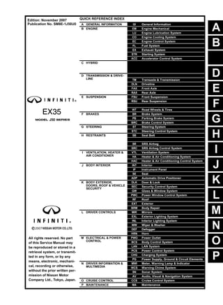
QUICK REFERENCE INDEX
A GENERAL INFORMATION GI General Information
B ENGINE EM Engine Mechanical
LU Engine Lubrication System
CO Engine Cooling System
EC Engine Control System
FL Fuel System
EX Exhaust System
STR Starting System
ACC Accelerator Control System
C HYBRID HBC Hybrid Control System
HBB Hybrid Battery System
HBR Hybrid Brake System
D TRANSMISSION & DRIVE-
LINE
CL Clutch
TM Transaxle & Transmission
DLN Driveline
FAX Front Axle
RAX Rear Axle
E SUSPENSION FSU Front Suspension
RSU Rear Suspension
SCS Suspension Control System
WT Road Wheels & Tires
F BRAKES BR Brake System
PB Parking Brake System
BRC Brake Control System
G STEERING ST Steering System
STC Steering Control System
H RESTRAINTS SB Seat Belt
SBC Seat Belt Control System
SR SRS Airbag
SRC SRS Airbag Control System
I VENTILATION, HEATER &
AIR CONDITIONER
VTL Ventilation System
HA Heater & Air Conditioning System
HAC Heater & Air Conditioning Control System
J BODY INTERIOR INT Interior
IP Instrument Panel
SE Seat
ADP Automatic Drive Positioner
K BODY EXTERIOR,
DOORS, ROOF & VEHICLE
SECURITY
DLK Door & Lock
SEC Security Control System
GW Glass & Window System
PWC Power Window Control System
RF Roof
EXT Exterior
BRM Body Repair
L DRIVER CONTROLS MIR Mirrors
EXL Exterior Lighting System
INL Interior Lighting System
WW Wiper & Washer
DEF Defogger
HRN Horn
M ELECTRICAL & POWER
CONTROL
PWO Power Outlet
BCS Body Control System
LAN LAN System
PCS Power Control System
CHG Charging System
PG Power Supply, Ground & Circuit Elements
N DRIVER INFORMATION &
MULTIMEDIA
MWI Meter, Warning Lamp & Indicator
WCS Warning Chime System
SN Sonar System
AV Audio, Visual & Navigation System
O CRUISE CONTROL CCS Cruise Control System
P MAINTENANCE MA Maintenance
All rights reserved. No part
of this Service Manual may
be reproduced or stored in a
retrieval system, or transmit-
ted in any form, or by any
means, electronic, mechani-
cal, recording or otherwise,
without the prior written per-
mission of Nissan Motor
Company Ltd., Tokyo, Japan.
Edition: November 2007
Publication No. SM8E-1J50U0
2. This manual contains maintenance and repair procedure for the 2008
INFINITI EX35.
In order to assure your safety and the efficient functioning of the vehicle,
this manual should be read thoroughly. It is especially important that the
PRECAUTIONS in the GI section be completely understood before starting
any repair task.
All information in this manual is based on the latest product information
at the time of publication. The right is reserved to make changes in specifi-
cations and methods at any time without notice.
IMPORTANT SAFETY NOTICE
The proper performance of service is essential for both the safety of
the technician and the efficient functioning of the vehicle.
The service methods in this Service Manual are described in such a
manner that the service may be performed safely and accurately.
Service varies with the procedures used, the skills of the technician
and the tools and parts available. Accordingly, anyone using service
procedures, tools or parts which are not specifically recommended
by NISSAN must first be completely satisfied that neither personal
safety nor the vehicle’s safety will be jeopardized by the service
method selected.
3. QUICK REFERENCE CHART EX35
QUICK REFERENCE CHART EX35 PFP:00000
ENGINE TUNE-UP DATA (VQ35HR) ELS0003W
Engine model VQ35HR
Firing order 1-2-3-4-5-6
Idle speed
A/T (In “N” position)
rpm 650 ± 50
Ignition timing
(BTDC at idle speed)
16° ± 5° (without 4WAS)
11° ± 5° (with 4WAS)
CO% at idle 0.7 - 9.9 % and engine runs smoothly
Tensions of drive belts Auto adjustment by auto tensioner
Radiator cap relief pressure kPa (kg/cm2 , psi)
Standard 122.3 - 151.7 (1.2 - 1.5, 18 - 22)
Limit 107 (1.1, 16)
Cooling system leakage testing pressure kPa (kg/cm2
, psi)
157 (1.6, 23)
Compression pressure kPa (kg/cm2
, psi)/rpm
Standard 1,275 (13.0, 185)/300
Minimum 981 (10.0, 142)/300
Differential limit between cylinders 98 (1.0, 14)/300
Spark plug
(Iridium-tipped type)
Make DENSO
Standard type FXE22HR11
Gap (Nominal) mm (in) 1.1 (0.043)
2008
4. QUICK REFERENCE CHART EX35
FRONT WHEEL ALIGNMENT ELS0003X
2WD
Measure value under unladen* conditions.
*: Fuel, engine coolant and lubricant are full. Spare tire, jack, hand tools and mats are in designated positions.
AWD
Measure value under unladen* conditions.
*: Fuel, engine coolant and lubricant are full. Spare tire, jack, hand tools and mats are in designated positions.
Item Standard
Camber
Degree minute (Decimal degree)
Minimum –0° 40′ (–0.66°)
Nominal 0° 05′ (0.08°)
Maximum 0° 50′ (0.83°)
Left and right difference 0° 33′ (0.55°) or less
Caster
Degree minute (Decimal degree)
Minimum 3° 30′ (3.50°)
Nominal 4° 15′ (4.25°)
Maximum 5° 00′ (5.00°)
Left and right difference 0° 39′ (0.65°) or less
Kingpin inclination
Degree minute (Decimal degree)
Minimum 6° 05′ (6.09°)
Nominal 6° 50′ (6.83°)
Maximum 7° 35′ (7.58°)
Total toe-in
Distance
Minimum 0 mm (0 in)
Nominal In 1 mm (0.04 in)
Maximum In 2 mm (0.08 in)
Angle (Left wheel or right wheel)
Degree minute (Decimal degree)
Minimum 0° 00 (0.00°)
Nominal In 0° 02′ 24″ (0.04°)
Maximum In 0° 04′ 48″ (0.08°)
Camber
Degree minute (Decimal degree)
Minimum –1° 05′ (–1.08°)
Nominal –0° 20′ (–0.33°)
Maximum 0° 25′ (0.42°)
Left and right difference 0° 33′ (0.55°) or less
Caster
Degree minute (Decimal degree)
Minimum 3° 25′ (3.42°)
Nominal 4° 10′ (4.17°)
Maximum 4° 55′ (4.91°)
Left and right difference 0° 39′ (0.65°) or less
Kingpin inclination
Degree minute (Decimal degree)
Minimum 6° 35′ (6.58°)
Nominal 7° 20′ (7.33°)
Maximum 8° 05′ (8.08°)
Total toe-in
Distance
Minimum 0 mm (0 in)
Nominal In 1 mm (0.04 in)
Maximum In 2 mm (0.08 in)
Angle (Left wheel or right wheel)
Degree minute (Decimal degree)
Minimum 0° 00′ (0.00°)
Nominal In 0° 02′ 24″ (0.04°)
Maximum In 0° 04′ 48″(0.08°)
2008
5. QUICK REFERENCE CHART EX35
REAR WHEEL ALIGNMENT ELS0003Y
Measure value under unladen* conditions.
*: Fuel, engine coolant and lubricant are full. Spare tire, jack, hand tools and mats are in designated positions.
BRAKE PEDAL
Unit: mm (in)
FRONT DISK BRAKE
Unit: mm (in)
REAR DISK BRAKE
Unit: mm (in)
REFILL CAPACITIES ELS00040
Item Standard
Camber
Degree minute (Decimal degree)
Minimum –1° 05′ (–1.08°)
Nominal –0° 35′ (–0.58°)
Maximum –0° 05′ (–0.09°)
Total toe-in
Distance
Minimum 0 mm (0 in)
Nominal In 2.9 mm (0.114 in)
Maximum In 5.8 mm (0.228 in)
Angle (Left wheel or right wheel)
Degree minute (Decimal degree)
Minimum 0° 00′ (0.00°)
Nominal In 0° 07′ (0.12°)
Maximum In 0° 14′ (0.23°)
Item Standard
Brake pedal height 171.5 – 181.5 (6.75 – 7.15)
Clearance between the stop lamp switch and ASCD brake switch
threaded end and the stopper rubber
0.74 – 1.96 (0.0291 – 0.0772)
Brake pedal play 3.0 – 11.0 (0.118 – 0.433)
Depressed brake pedal height
[Depressing 490 N (50 kg, 110 lb) while turning the engine ON]
114.0 (4.49) or more
Item Limit
Brake pad Wear thickness 2.0 (0.079)
Disc rotor Wear thickness 26.0 (1.024)
Thickness variation (measured at 8 positions) 0.015 (0.0006)
Runout (with it attached to the vehicle) 0.035 (0.0014)
Item Limit
Brake pad Wear thickness 2.0 (0.079)
Disc rotor Wear thickness 14.0 (0.551)
Thickness variation (measured at 8 positions) 0.015 (0.0006)
Runout (with it attached to the vehicle) 0.055 (0.0022)
UNIT Liter US measure
Fuel tank Applox. 76 20 gal
Engine Coolant ( With reservoir tank ) at MAX level 8.6 9-1/8 qt
2008
6. QUICK REFERENCE CHART EX35
Engine oil
Drain and refill
With oil filter change 4.9 5-1/8 qt
Without oil filter change 4.6 4-7/8 qt
Dry engine (Overhaul) 5.7 6 qt
Transmission A/T 10.3 10-7/8 qt
Transfer 1.25 2-5/8 pt
Final drive
Front 0.65 1-3/8 pt
Rear 1.4 3 pt
Power steering system 1.0 1-1/8 qt
Air conditioning system
Compressor oil 0.15 5.03 fl oz
Refrigerant 0.55 kg 1.21 lb
UNIT Liter US measure
2008
7. GI-1
GENERAL INFORMATION
C
D
E
F
G
H
I
J
K
L
M
B
GI
SECTION GI
N
O
P
CONTENTS
GENERAL INFORMATION
HOW TO USE THIS MANUAL ...................... 3
HOW TO USE THIS MANUAL ............................ 3
Description ................................................................3
Terms ........................................................................3
Units ..........................................................................3
Contents ....................................................................3
Relation between Illustrations and Descriptions .......4
Components ..............................................................4
HOW TO FOLLOW TROUBLE DIAGNOSES..... 6
Description ................................................................6
How to Follow Test Groups in Trouble Diagnosis......6
Key to Symbols Signifying Measurements or Pro-
cedures .....................................................................7
HOW TO READ WIRING DIAGRAMS ................ 9
Connector Symbols ...................................................9
Sample/Wiring Diagram -Example- .........................10
Description ..............................................................11
ABBREVIATIONS ..............................................13
Abbreviation List ......................................................13
TIGHTENING TORQUE OF STANDARD
BOLTS ................................................................14
Tightening Torque Table .........................................14
RECOMMENDED CHEMICAL PRODUCTS
AND SEALANTS ................................................15
Recommended Chemical Products and Sealants....15
TERMINOLOGY .................................................16
SAE J1930 Terminology List ...................................16
FEATURES OF NEW MODEL .....................20
IDENTIFICATION INFORMATION .....................20
Model Variation .......................................................20
Information About Identification or Model Code ......20
Dimensions .............................................................22
Wheels & Tires ........................................................22
PRECAUTION ..............................................23
PRECAUTIONS .................................................23
Description ...............................................................23
Precaution for Supplemental Restraint System
(SRS) "AIR BAG" and "SEAT BELT PRE-TEN-
SIONER" .................................................................23
Precautions For Xenon Headlamp Service .............23
Precaution Necessary for Steering Wheel Rota-
tion after Battery Disconnect ...................................23
Precaution for Procedure without Cowl Top Cover....24
General Precautions ................................................24
Three Way Catalyst .................................................26
Multiport Fuel Injection System or Engine Control
System .....................................................................26
Hoses ......................................................................26
Engine Oils ..............................................................27
Air Conditioning .......................................................27
FUEL ..........................................................................27
FUEL : Unleaded Premium Gasoline Recom-
mended ....................................................................28
LIFTING POINT .................................................29
Commercial Service Tools .......................................29
Garage Jack and Safety Stand and 2-Pole Lift .......29
Board-On Lift ...........................................................30
TOW TRUCK TOWING .....................................31
Tow Truck Towing ...................................................31
Vehicle Recovery (Freeing a Stuck Vehicle) ...........32
BASIC INSPECTION ...................................34
SERVICE INFORMATION FOR ELECTRICAL
INCIDENT ..........................................................34
Work Flow ................................................................34
Control Units and Electrical Parts ............................34
How to Check Terminal ...........................................35
Intermittent Incident .................................................38
Circuit Inspection .....................................................41
Revision: 2007 November 2008 EX35
8. GI-2
CONSULT-III/GST CHECKING SYSTEM ......... 46
Description .............................................................. 46
CONSULT-III Function and System Application*1... 46
CONSULT-III/GST Data Link Connector (DLC)
Circuit ..................................................................... 46
Wiring Diagram - CONSULT-III/GST CHECKING
SYSTEM - ............................................................... 48
INSPECTION AND ADJUSTMENT ................... 52
ADDITIONAL SERVICE WHEN REMOVING BAT-
TERY NEGATIVE TERMINAL .................................. 52
ADDITIONAL SERVICE WHEN REMOVING
BATTERY NEGATIVE TERMINAL : Required
Procedure After Battery Disconnection ................... 52
Revision: 2007 November 2008 EX35
9. HOW TO USE THIS MANUAL
GI-3
< HOW TO USE THIS MANUAL >
C
D
E
F
G
H
I
J
K
L
M
B
GI
N
O
P
HOW TO USE THIS MANUAL
HOW TO USE THIS MANUAL
Description INFOID:0000000003131598
This volume explains “Removal, Disassembly, Installation, Inspection and Adjustment” and “Trouble Diag-
noses”.
Terms INFOID:0000000003131599
• The captions WARNING and CAUTION warn you of steps that must be followed to prevent personal injury
and/or damage to some part of the vehicle.
WARNING indicates the possibility of personal injury if instructions are not followed.
CAUTION indicates the possibility of component damage if instructions are not followed.
BOLD TYPED STATEMENTS except WARNING and CAUTION give you helpful information.
Standard value: Tolerance at inspection and adjustment.
Limit value: The maximum or minimum limit value that should not be exceeded at inspection and adjust-
ment.
Units INFOID:0000000003131600
• The UNITS given in this manual are primarily expressed as the SI UNIT (International System of Unit), and
alternatively expressed in the metric system and in the yard/pound system.
Also with regard to tightening torque of bolts and nuts, there are descriptions both about range and about the
standard tightening torque.
“Example”
Range
Standard
Contents INFOID:0000000003566430
• A QUICK REFERENCE INDEX, a black tab (e.g. ) is provided on the first page. You can quickly find the
first page of each section by matching it to the section's black tab.
• THE CONTENTS are listed on the first page of each section.
• THE TITLE is indicated on the upper portion of each page and shows the part or system.
• THE PAGE NUMBER of each section consists of two or three letters which designate the particular section
and a number (e.g. “BR-5”).
• THE SMALL ILLUSTRATIONS show the important steps such as inspection, use of special tools, knacks of
work and hidden or tricky steps which are not shown in the previous large illustrations.
Assembly, inspection and adjustment procedures for the complicated units such as the automatic transaxle
or transmission, etc. are presented in a step-by-step format where necessary.
Outer Socket Lock Nut : 59 - 78 N·m (6.0 - 8.0 kg-m, 43 - 58 ft-lb)
Drive Shaft Installation Bolt : 44.3 N·m (4.5 kg-m, 33 ft-lb)
Revision: 2007 November 2008 EX35
10. GI-4
< HOW TO USE THIS MANUAL >
HOW TO USE THIS MANUAL
Relation between Illustrations and Descriptions INFOID:0000000003131602
The following sample explains the relationship between the part description in an illustration, the part name in
the text and the service procedures.
Components INFOID:0000000003131603
• THE LARGE ILLUSTRATIONS are exploded views (see the following) and contain tightening torques, lubri-
cation points, section number of the PARTS CATALOG (e.g. SEC. 440) and other information necessary to
perform repairs.
The illustrations should be used in reference to service matters only. When ordering parts, refer to the appro-
priate PARTS CATALOG.
Components shown in an illustration may be identified by a circled number. When this style of illustration is
used, the text description of the components will follow the illustration.
SAIA0519E
Revision: 2007 November 2008 EX35
11. HOW TO USE THIS MANUAL
GI-5
< HOW TO USE THIS MANUAL >
C
D
E
F
G
H
I
J
K
L
M
B
GI
N
O
P
SYMBOLS
1. Union bolt 2. Copper washer 3. Brake hose
4. Cap 5. Bleed valve 6. Sliding pin bolt
7. Piston seal 8. Piston 9. Piston boot
10. Cylinder body 11. Sliding pin 12. Torque member mounting bolt
13. Washer 14. Sliding pin boot 15. Bushing
16. Torque member 17. Inner shim cover 18. Inner shim
19. Inner pad 20. Pad retainer 21. Pad wear sensor
22. Outer pad 23. Outer shim 24. Outer shim cover
1: PBC (Poly Butyl Cuprysil) grease
or silicone-based grease
2: Rubber grease : Brake fluid
Refer to GI section for additional symbol definitions.
SFIA2959E
SAIA0749E
Revision: 2007 November 2008 EX35
12. GI-6
< HOW TO USE THIS MANUAL >
HOW TO FOLLOW TROUBLE DIAGNOSES
HOW TO FOLLOW TROUBLE DIAGNOSES
Description INFOID:0000000003131604
NOTICE:
Trouble diagnoses indicate work procedures required to diagnose problems effectively. Observe the following
instructions before diagnosing.
• Before performing trouble diagnoses, read the “Work Flow” in each section.
• After repairs, re-check that the problem has been completely eliminated.
• Refer to Component Parts and Harness Connector Location for the Systems described in each section for
identification/location of components and harness connectors.
• When checking circuit continuity, ignition switch should be OFF.
• Refer to the Circuit Diagram for quick pinpoint check.
If you need to check circuit continuity between harness connectors in more detail, such as when a sub-har-
ness is used, refer to Wiring Diagram in each individual section and Harness Layout in PG section for identi-
fication of harness connectors.
• Before checking voltage at connectors, check battery voltage.
• After accomplishing the Diagnosis Procedures and Electrical Components Inspection, make sure that all
harness connectors are reconnected as they were.
How to Follow Test Groups in Trouble Diagnosis INFOID:0000000003131605
1. Test group number and test group title
• Test group number and test group title are shown in the upper portion of each test group.
2. Work and diagnosis procedure
• Start to diagnose a problem using procedures indicated in enclosed test groups.
3. Questions and results
• Questions and required results are indicated in test group.
4. Action
• Next action for each test group is indicated based on result of each question.
JPAIA0021GB
Revision: 2007 November 2008 EX35
13. HOW TO FOLLOW TROUBLE DIAGNOSES
GI-7
< HOW TO USE THIS MANUAL >
C
D
E
F
G
H
I
J
K
L
M
B
GI
N
O
P
Key to Symbols Signifying Measurements or Procedures INFOID:0000000003131606
SAIA1539E
Revision: 2007 November 2008 EX35
14. GI-8
< HOW TO USE THIS MANUAL >
HOW TO FOLLOW TROUBLE DIAGNOSES
SAIA1540E
Revision: 2007 November 2008 EX35
15. HOW TO READ WIRING DIAGRAMS
GI-9
< HOW TO USE THIS MANUAL >
C
D
E
F
G
H
I
J
K
L
M
B
GI
N
O
P
HOW TO READ WIRING DIAGRAMS
Connector Symbols INFOID:0000000003131607
Most of connector symbols in wiring diagrams are shown from the terminal side.
• Connector symbols shown from the terminal side are enclosed by
a single line and followed by the direction mark.
• Connector symbols shown from the harness side are enclosed by
a double line and followed by the direction mark.
• Certain systems and components, especially those related to
OBD, may use a new style slide-locking type harness connector.
For description and how to disconnect, refer to PG section,
“Description”, “HARNESS CONNECTOR”.
• Male and female terminals
Connector guides for male terminals are shown in black and
female terminals in white in wiring diagrams.
SAIA0257E
SGI363
Revision: 2007 November 2008 EX35
16. GI-10
< HOW TO USE THIS MANUAL >
HOW TO READ WIRING DIAGRAMS
Sample/Wiring Diagram -Example- INFOID:0000000003131608
• For detail, refer to following GI-11, "Description".
JCAWA0005GB
Revision: 2007 November 2008 EX35
17. HOW TO READ WIRING DIAGRAMS
GI-11
< HOW TO USE THIS MANUAL >
C
D
E
F
G
H
I
J
K
L
M
B
GI
N
O
P
Description INFOID:0000000003131609
SWITCH POSITIONS
Switches are shown in wiring diagrams as if the vehicle is in the “normal” condition.
A vehicle is in the “normal” condition when:
Number Item Description
1 Power supply • This means the power supply of fusible link or fuse.
2 Fusible link • “X” means the fusible link.
3
Number of fusible link/
fuse
• This means the number of fusible link or fuse location.
4 Fuse • “/” means the fuse.
5
Current rating of fus-
ible link/fuse
• This means the current rating of the fusible link or fuse.
6 Optional splice • The open circle shows that the splice is optional depending on vehicle application.
7 Connector number
• The letter shows which harness the connector is located in.
• Example “M”: main harness. For detail and to locate the connector, refer to PG-78, "How
To Read Harness Layout", PG-80, "Main Harness".
8 Splice • The shaded circle “ ” means the splice.
9 Page crossing • This circuit continues to an adjacent page.
10 Option abbreviation • This means the vehicle specifications which layouts the circuit between “ ”.
11 Relay • This shows an internal representation of the relay.
12 Option description • This shows a description of the option abbreviation used on the page.
13 Switch
• This shows that continuity exists between terminals 1 and 2 when the switch is in the A
position. Continuity exists between terminals 1 and 3 when the switch is in the B position.
14 Circuit (Wiring) • This means the wiring.
15 System branch • This shows that the circuit is branched to other systems.
16 Shielded line • The line enclosed by broken line circle shows shield wire.
17 Component name • This shows the name of a component.
18 Ground (GND) • This shows the ground connection.
19 Connector
• This means the connector information.
• This unit-side is described by the connector symbols.
20 Connectors • This means that a transmission line bypasses two connectors or more.
21 Wire color
• This shows a code for the color of the wire.
B = Black
W = White
R = Red
G = Green
L = Blue
Y = Yellow
LG = Light Green
BR = Brown
OR or O = Orange
P = Pink
PU or V (Violet) = Purple
GY or GR = Gray
SB = Sky Blue
CH = Dark Brown
DG = Dark Green
• When the wire color is striped, the base color is given first, followed by the stripe color as
shown below:
Example: L/W = Blue with White Stripe
22 Terminal number • This means the terminal number of a connector.
Revision: 2007 November 2008 EX35
18. GI-12
< HOW TO USE THIS MANUAL >
HOW TO READ WIRING DIAGRAMS
• ignition switch is “OFF”,
• doors, hood and trunk lid/back door are closed,
• pedals are not depressed, and
• parking brake is released.
MULTIPLE SWITCH
The continuity of multiple switch is described in two ways as shown below.
• The switch chart is used in schematic diagrams.
• The switch diagram is used in wiring diagrams.
SGI860
JSAIA0017GB
Revision: 2007 November 2008 EX35
19. ABBREVIATIONS
GI-13
< HOW TO USE THIS MANUAL >
C
D
E
F
G
H
I
J
K
L
M
B
GI
N
O
P
ABBREVIATIONS
Abbreviation List INFOID:0000000003131610
The following ABBREVIATIONS are used:
ABBREVIATION DESCRIPTION
A/C Air Conditioner
A/T Automatic Transaxle/Transmission
ATF Automatic Transmission Fluid
D1 Drive range 1st gear
D2 Drive range 2nd gear
D3 Drive range 3rd gear
D4 Drive range 4th gear
FR, RR Front, Rear
LH, RH Left-Hand, Right-Hand
M/T Manual Transaxle/Transmission
OD Overdrive
P/S Power Steering
SAE Society of Automotive Engineers, Inc.
SDS Service Data and Specifications
SST Special Service Tools
2WD 2-Wheel Drive
22 2nd range 2nd gear
21 2nd range 1st gear
12 1st range 2nd gear
11 1st range 1st gear
Revision: 2007 November 2008 EX35
21. RECOMMENDED CHEMICAL PRODUCTS AND SEALANTS
GI-15
< HOW TO USE THIS MANUAL >
C
D
E
F
G
H
I
J
K
L
M
B
GI
N
O
P
RECOMMENDED CHEMICAL PRODUCTS AND SEALANTS
Recommended Chemical Products and Sealants INFOID:0000000003131612
Refer to the following chart for help in selecting the appropriate chemical product or sealant.
Product Description Purpose
Nissan North America
Part No. (USA)
Nissan Canada Part
No. (Canada)
Aftermarket Cross-
reference Part Nos.
1
Rear View Mirror Adhe-
sive
Used to permanently re-
mount rear view mirrors to
windows.
999MP-AM000P 99998-50505 Permatex 81844
2
Anaerobic Liquid Gas-
ket
For metal-to-metal flange
sealing.
Can fill a 0.38 mm (0.015
inch) gap and provide in-
stant sealing for most pow-
ertrain applications.
999MP-AM001P 99998-50503
Permatex 51813 and
51817
3
High Performance
Thread Sealant
Provides instant sealing on
any threaded straight or
parallel threaded fitting.
(Thread sealant only, no
locking ability.)
• Do not use on plastic.
999MP-AM002P 999MP-AM002P Permatex 56521
4 Silicone RTV
Gasket Maker
999MP-AM003P
(Ultra Grey)
99998-50506
(Ultra Grey)
Permatex Ultra Grey
82194;
Three Bond
1207,1215, 1216,
1217F, 1217G and
1217H
Nissan RTV Part No.
999MP-A7007
Gasket Maker for Maxima/
Quest 5-speed automatic
transmission
(RE5F22A)
– –
Three Bond 1281B
or exact equivalent in
its quality
5
High Temperature,
High Strength Thread
Locking Sealant (Red)
Threadlocker 999MP-AM004P 999MP-AM004P
Permatex 27200;
Three Bond 1360,
1360N, 1305 N&P,
1307N, 1335,
1335B, 1363B,
1377C, 1386B, D&E
and 1388
Loctite 648
6
Medium Strength
Thread Locking Seal-
ant (Blue)
Threadlocker (service tool
removable)
999MP-AM005P 999MP-AM005P
Permatex 24200,
24206, 24240,
24283 and 09178;
Three Bond 1322,
1322N, 1324 D&N,
1333D, 1361C,
1364D, 1370C and
1374
Revision: 2007 November 2008 EX35
22. GI-16
< HOW TO USE THIS MANUAL >
TERMINOLOGY
TERMINOLOGY
SAE J1930 Terminology List INFOID:0000000003131613
All emission related terms used in this publication in accordance with SAE J1930 are listed. Accordingly, new
terms, new acronyms/abbreviations and old terms are listed in the following chart.
NEW TERM
NEW ACRONYM /
ABBREVIATION
OLD TERM
Air cleaner ACL Air cleaner
Barometric pressure BARO ***
Barometric pressure sensor-BCDD BAROS-BCDD BCDD
Camshaft position CMP ***
Camshaft position sensor CMPS Crank angle sensor
Canister *** Canister
Carburetor CARB Carburetor
Charge air cooler CAC Intercooler
Closed loop CL Closed loop
Closed throttle position switch CTP switch Idle switch
Clutch pedal position switch CPP switch Clutch switch
Continuous fuel injection system CFI system ***
Continuous trap oxidizer system CTOX system ***
Crankshaft position CKP ***
Crankshaft position sensor CKPS ***
Data link connector DLC ***
Diagnostic test mode DTM Diagnostic mode
Diagnostic test mode selector DTM selector Diagnostic mode selector
Diagnostic test mode I DTM I Mode I
Diagnostic test mode II DTM II Mode II
Diagnostic trouble code DTC Malfunction code
Direct fuel injection system DFI system ***
Distributor ignition system DI system Ignition timing control
Early fuel evaporation-mixture heater EFE-mixture heater Mixture heater
Early fuel evaporation system EFE system Mixture heater control
Electrically erasable programmable read
only memory
EEPROM ***
Electronic ignition system EI system Ignition timing control
Engine control EC ***
Engine control module ECM ECCS control unit
Engine coolant temperature ECT Engine temperature
Engine coolant temperature sensor ECTS Engine temperature sensor
Engine modification EM ***
Engine speed RPM Engine speed
Erasable programmable read only memory EPROM ***
Evaporative emission canister EVAP canister Canister
Evaporative emission system EVAP system Canister control solenoid valve
Exhaust gas recirculation valve EGR valve EGR valve
Revision: 2007 November 2008 EX35
23. TERMINOLOGY
GI-17
< HOW TO USE THIS MANUAL >
C
D
E
F
G
H
I
J
K
L
M
B
GI
N
O
P
Exhaust gas recirculation control-BPT
valve
EGRC-BPT valve BPT valve
Exhaust gas recirculation control-solenoid
valve
EGRC-solenoid valve EGR control solenoid valve
Exhaust gas recirculation temperature sen-
sor EGRT sensor Exhaust gas temperature sensor
EGR temperature sensor
Flash electrically erasable programmable
read only memory
FEEPROM ***
Flash erasable programmable read only
memory
FEPROM ***
Flexible fuel sensor FFS ***
Flexible fuel system FF system ***
Fuel pressure regulator *** Pressure regulator
Fuel pressure regulator control solenoid
valve
*** PRVR control solenoid valve
Fuel trim FT ***
Heated Oxygen sensor HO2S Exhaust gas sensor
Idle air control system IAC system Idle speed control
Idle air control valve-air regulator IACV-air regulator Air regulator
Idle air control valve-auxiliary air control
valve
IACV-AAC valve Auxiliary air control (AAC) valve
Idle air control valve-FICD solenoid valve IACV-FICD solenoid valve FICD solenoid valve
Idle air control valve-idle up control sole-
noid valve
IACV-idle up control solenoid valve Idle up control solenoid valve
Idle speed control-FI pot ISC-FI pot FI pot
Idle speed control system ISC system ***
Ignition control IC ***
Ignition control module ICM ***
Indirect fuel injection system IFI system ***
Intake air IA Air
Intake air temperature sensor IAT sensor Air temperature sensor
Knock *** Detonation
Knock sensor KS Detonation sensor
Malfunction indicator lamp MIL Check engine light
Manifold absolute pressure MAP ***
Manifold absolute pressure sensor MAPS ***
Manifold differential pressure MDP ***
Manifold differential pressure sensor MDPS ***
Manifold surface temperature MST ***
Manifold surface temperature sensor MSTS ***
Manifold vacuum zone MVZ ***
Manifold vacuum zone sensor MVZS ***
Mass air flow sensor MAFS Air flow meter
Mixture control solenoid valve MC solenoid valve Air-fuel ratio control solenoid valve
Multiport fuel injection system MFI system Fuel injection control
NEW TERM
NEW ACRONYM /
ABBREVIATION
OLD TERM
Revision: 2007 November 2008 EX35
24. GI-18
< HOW TO USE THIS MANUAL >
TERMINOLOGY
Nonvolatile random access memory NVRAM ***
On board diagnostic system OBD system Self-diagnosis
Open loop OL Open loop
Oxidation catalyst OC Catalyst
Oxidation catalytic converter system OC system ***
Oxygen sensor O2S Exhaust gas sensor
Park position switch *** Park switch
Park/neutral position switch PNP switch
Park/neutral switch
Inhibitor switch
Neutral position switch
Periodic trap oxidizer system PTOX system ***
Positive crankcase ventilation PCV Positive crankcase ventilation
Positive crankcase ventilation valve PCV valve PCV valve
Powertrain control module PCM ***
Programmable read only memory PROM ***
Pulsed secondary air injection control sole-
noid valve
PAIRC solenoid valve AIV control solenoid valve
Pulsed secondary air injection system PAIR system Air induction valve (AIV) control
Pulsed secondary air injection valve PAIR valve Air induction valve
Random access memory RAM ***
Read only memory ROM ***
Scan tool ST ***
Secondary air injection pump AIR pump ***
Secondary air injection system AIR system ***
Sequential multiport fuel injection system SFI system Sequential fuel injection
Service reminder indicator SRI ***
Simultaneous multiport fuel injection sys-
tem
*** Simultaneous fuel injection
Smoke puff limiter system SPL system ***
Supercharger SC ***
Supercharger bypass SCB ***
System readiness test SRT ***
Thermal vacuum valve TVV Thermal vacuum valve
Three way catalyst TWC Catalyst
Three way catalytic converter system TWC system ***
Three way + oxidation catalyst TWC + OC Catalyst
Three way + oxidation catalytic converter
system
TWC + OC system ***
Throttle body TB
Throttle chamber
SPI body
Throttle body fuel injection system TBI system Fuel injection control
Throttle position TP Throttle position
Throttle position sensor TPS Throttle sensor
Throttle position switch TP switch Throttle switch
Torque converter clutch solenoid valve TCC solenoid valve
Lock-up cancel solenoid
Lock-up solenoid
NEW TERM
NEW ACRONYM /
ABBREVIATION
OLD TERM
Revision: 2007 November 2008 EX35
25. TERMINOLOGY
GI-19
< HOW TO USE THIS MANUAL >
C
D
E
F
G
H
I
J
K
L
M
B
GI
N
O
P
***: Not applicable
Transmission control module TCM A/T control unit
Turbocharger TC Turbocharger
Vehicle speed sensor VSS Vehicle speed sensor
Volume air flow sensor VAFS Air flow meter
Warm up oxidation catalyst WU-OC Catalyst
Warm up oxidation catalytic converter sys-
tem
WU-OC system ***
Warm up three way catalyst WU-TWC Catalyst
Warm up three way catalytic converter sys-
tem
WU-TWC system ***
Wide open throttle position switch WOTP switch Full switch
NEW TERM
NEW ACRONYM /
ABBREVIATION
OLD TERM
Revision: 2007 November 2008 EX35
26. GI-20
< FEATURES OF NEW MODEL >
IDENTIFICATION INFORMATION
FEATURES OF NEW MODEL
IDENTIFICATION INFORMATION
Model Variation INFOID:0000000003131614
Model variation code (Prefix and suffix designations)
Information About Identification or Model Code INFOID:0000000003131615
IDENTIFICATION NUMBER
Dstination Body Engine Transmission Axle Grade Model
USA
Wagon VQ35HR 5A/T
2WD
Base TLTALQN-EUA
Journey TLTALTN-EUA
AWD
Base TLTNLQN-EUA
Journey TLTNLTN-EUA
Canada
Base TLTNLQN-ENA
Journey TLTNLTN-ENA
JPAIA0240GB
JPAIA0241ZZ
Revision: 2007 November 2008 EX35
27. IDENTIFICATION INFORMATION
GI-21
< FEATURES OF NEW MODEL >
C
D
E
F
G
H
I
J
K
L
M
B
GI
N
O
P
VEHICLE IDENTIFICATION NUMBER ARRANGEMENT
IDENTIFICATION PLATE
ENGINE SERIAL NUMBER
1. Vehicle identification plate 2. Emission control information label 3.
Vehicle identification number (Chassis
number)
4. Vehicle identification number plate 5. Tire and loading information label 6. FMVSS certification label
7. Air conditioner specification labe
JPAIA0242GB
JPAIA0004ZZ
1. Type 2. Vehicle identification number (Chassis number) 3. Model variation code
4. Body color code 5. Trim color code 6. Engine model
7. Engine displacement 8. Transmission model 9. Axle model
JPAIA0005ZZ
Revision: 2007 November 2008 EX35
28. GI-22
< FEATURES OF NEW MODEL >
IDENTIFICATION INFORMATION
AUTOMATIC TRANSMISSION NUMBER
Dimensions INFOID:0000000003131616
Unit: mm (in)
*1: 2WD 17-in tire models
*2: 2WD 18-in tire models
*3: AWD 17-in tire models
*4: AWD 18-in tire models
*5: Models without roof rack
*6: Models with roof rack
Wheels & Tires INFOID:0000000003131617
PAIA0054E
Overall length 4,630 (182.3)
Overall width 1,800 (70.9)
Overall height
1,570 (61.8)*5
1,590 (62.6)*6
Front tread
1,535 (60.4)*1
1,530 (60.2)*2
1,545 (60.8)*3
1,540 (60.6)*4
Rear tread
1,550 (61.0)*1
,*3
1,545 (60.8)*2
,*4
Wheelbase 2,850 (112.2)
Application Conventional Spare
Road wheel/offset mm (in)
17 X 7-1/2J Aluminum/45 (1.77)
17 × 4T Aluminum/30 (1.18)
18 X 8J Aluminum/47 (1.85)
Tire size
P225/60R17 98V
T165/80R17
P225/55R18 97V
Revision: 2007 November 2008 EX35
29. PRECAUTIONS
GI-23
< PRECAUTION >
C
D
E
F
G
H
I
J
K
L
M
B
GI
N
O
P
PRECAUTION
PRECAUTIONS
Description INFOID:0000000003131618
Observe the following precautions to ensure safe and proper servicing. These precautions are not
described in each individual section.
Precaution for Supplemental Restraint System (SRS) "AIR BAG" and "SEAT BELT
PRE-TENSIONER" INFOID:0000000003566319
The Supplemental Restraint System such as “AIR BAG” and “SEAT BELT PRE-TENSIONER”, used along
with a front seat belt, helps to reduce the risk or severity of injury to the driver and front passenger for certain
types of collision. This system includes seat belt switch inputs and dual stage front air bag modules. The SRS
system uses the seat belt switches to determine the front air bag deployment, and may only deploy one front
air bag, depending on the severity of a collision and whether the front occupants are belted or unbelted.
Information necessary to service the system safely is included in the “SRS AIRBAG” and “SEAT BELT” of this
Service Manual.
WARNING:
• To avoid rendering the SRS inoperative, which could increase the risk of personal injury or death in
the event of a collision which would result in air bag inflation, all maintenance must be performed by
an authorized NISSAN/INFINITI dealer.
• Improper maintenance, including incorrect removal and installation of the SRS, can lead to personal
injury caused by unintentional activation of the system. For removal of Spiral Cable and Air Bag
Module, see the “SRS AIRBAG”.
• Do not use electrical test equipment on any circuit related to the SRS unless instructed to in this
Service Manual. SRS wiring harnesses can be identified by yellow and/or orange harnesses or har-
ness connectors.
Precautions For Xenon Headlamp Service INFOID:0000000003131620
WARNING:
Comply with the following warnings to prevent any serious accident.
• Disconnect the battery cable (negative terminal) or the power supply fuse before installing, remov-
ing, or touching the xenon headlamp (bulb included). The xenon headlamp contains high-voltage
generated parts.
• Never work with wet hands.
• Check the xenon headlamp ON-OFF status after assembling it to the vehicle. Never turn the xenon
headlamp ON in other conditions. Connect the power supply to the vehicle-side connector.
(Turning it ON outside the lamp case may cause fire or visual impairments.)
• Never touch the bulb glass immediately after turning it OFF. It is extremely hot.
CAUTION:
Comply with the following cautions to prevent any error and malfunction.
• Install the xenon bulb securely. (Insufficient bulb socket installation may melt the bulb, the connec-
tor, the housing, etc. by high-voltage leakage or corona discharge.)
• Never perform HID circuit inspection with a tester.
• Never touch the xenon bulb glass with hands. Never put oil and grease on it.
• Dispose of the used xenon bulb after packing it in thick vinyl without breaking it.
• Never wipe out dirt and contamination with organic solvent (thinner, gasoline, etc.).
Precaution Necessary for Steering Wheel Rotation after Battery Disconnect
INFOID:0000000003691858
NOTE:
• Before removing and installing any control units, first turn the push-button ignition switch to the LOCK posi-
tion, then disconnect both battery cables.
• After finishing work, confirm that all control unit connectors are connected properly, then re-connect both
battery cables.
• Always use CONSULT-III to perform self-diagnosis as a part of each function inspection after finishing work.
If a DTC is detected, perform trouble diagnosis according to self-diagnosis results.
Revision: 2007 November 2008 EX35
30. GI-24
< PRECAUTION >
PRECAUTIONS
This vehicle is equipped with a push-button ignition switch and a steering lock unit.
If the battery is disconnected or discharged, the steering wheel will lock and cannot be turned.
If turning the steering wheel is required with the battery disconnected or discharged, follow the procedure
below before starting the repair operation.
OPERATION PROCEDURE
1. Connect both battery cables.
NOTE:
Supply power using jumper cables if battery is discharged.
2. Turn the push-button ignition switch to ACC position.
(At this time, the steering lock will be released.)
3. Disconnect both battery cables. The steering lock will remain released with both battery cables discon-
nected and the steering wheel can be turned.
4. Perform the necessary repair operation.
5. When the repair work is completed, re-connect both battery cables. With the brake pedal released, turn
the push-button ignition switch from ACC position to ON position, then to LOCK position. (The steering
wheel will lock when the push-button ignition switch is turned to LOCK position.)
6. Perform self-diagnosis check of all control units using CONSULT-III.
Precaution for Procedure without Cowl Top Cover INFOID:0000000003566320
When performing the procedure after removing cowl top cover, cover
the lower end of windshield with urethane, etc.
General Precautions INFOID:0000000003131623
• Do not operate the engine for an extended period of time without
proper exhaust ventilation.
Keep the work area well ventilated and free of any inflammable
materials. Special care should be taken when handling any inflam-
mable or poisonous materials, such as gasoline, refrigerant gas,
etc. When working in a pit or other enclosed area, be sure to prop-
erly ventilate the area before working with hazardous materials.
Do not smoke while working on the vehicle.
• Before jacking up the vehicle, apply wheel chocks or other tire
blocks to the wheels to prevent the vehicle from moving. After jack-
ing up the vehicle, support the vehicle weight with safety stands at
the points designated for proper lifting before working on the vehi-
cle.
These operations should be done on a level surface.
• When removing a heavy component such as the engine or tran-
saxle/transmission, be careful not to lose your balance and drop
them. Also, do not allow them to strike adjacent parts, especially
the brake tubes and master cylinder.
PIIB3706J
SGI285
SGI231
Revision: 2007 November 2008 EX35
31. PRECAUTIONS
GI-25
< PRECAUTION >
C
D
E
F
G
H
I
J
K
L
M
B
GI
N
O
P
• Before starting repairs which do not require battery power:
Turn off ignition switch.
Disconnect the negative battery terminal.
• If the battery terminals are disconnected, recorded memory of
radio and each control unit is erased.
• To prevent serious burns:
Avoid contact with hot metal parts.
Do not remove the radiator cap when the engine is hot.
• Dispose of drained oil or the solvent used for cleaning parts in an
appropriate manner.
• Do not attempt to top off the fuel tank after the fuel pump nozzle
shuts off automatically.
Continued refueling may cause fuel overflow, resulting in fuel spray
and possibly a fire.
• Clean all disassembled parts in the designated liquid or solvent
prior to inspection or assembly.
• Replace oil seals, gaskets, packings, O-rings, locking washers,
cotter pins, self-locking nuts, etc. with new ones.
• Replace inner and outer races of tapered roller bearings and needle bearings as a set.
• Arrange the disassembled parts in accordance with their assembled locations and sequence.
• Do not touch the terminals of electrical components which use microcomputers (such as ECM).
Static electricity may damage internal electronic components.
• After disconnecting vacuum or air hoses, attach a tag to indicate the proper connection.
• Use only the fluids and lubricants specified in this manual.
• Use approved bonding agent, sealants or their equivalents when required.
• Use hand tools, power tools (disassembly only) and recommended
special tools where specified for safe and efficient service repairs.
• When repairing the fuel, oil, water, vacuum or exhaust systems,
check all affected lines for leaks.
• Before servicing the vehicle:
Protect fenders, upholstery and carpeting with appropriate covers.
Take caution that keys, buckles or buttons do not scratch paint.
WARNING:
To prevent ECM from storing the diagnostic trouble codes, do not carelessly disconnect the harness
connectors which are related to the engine control system and TCM (transmission control module)
SEF289H
SGI233
PBIC0190E
SGI234
Revision: 2007 November 2008 EX35
32. GI-26
< PRECAUTION >
PRECAUTIONS
system. The connectors should be disconnected only when working according to the WORK FLOW of
TROUBLE DIAGNOSES in EC and AT sections.
Three Way Catalyst INFOID:0000000003131624
If a large amount of unburned fuel flows into the catalyst, the catalyst temperature will be excessively high. To
prevent this, follow the instructions.
• Use unleaded gasoline only. Leaded gasoline will seriously damage the three way catalyst.
• When checking for ignition spark or measuring engine compression, make tests quickly and only when nec-
essary.
• Do not run engine when the fuel tank level is low, otherwise the engine may misfire, causing damage to the
catalyst.
Do not place the vehicle on flammable material. Keep flammable material off the exhaust pipe and the three
way catalyst.
Multiport Fuel Injection System or Engine Control System INFOID:0000000003131625
• Before connecting or disconnecting any harness connector for the
multiport fuel injection system or ECM:
Turn ignition switch to “OFF” position.
Disconnect negative battery terminal.
Otherwise, there may be damage to ECM.
• Before disconnecting pressurized fuel line from fuel pump to injec-
tors, be sure to release fuel pressure.
• Be careful not to jar components such as ECM and mass air flow
sensor.
Hoses INFOID:0000000003131626
HOSE REMOVAL AND INSTALLATION
• To prevent damage to rubber hose, do not pry off rubber hose with
tapered tool or screwdriver.
• To reinstall the rubber hose securely, make sure that hose insertion
length and orientation is correct. (If tube is equipped with hose
stopper, insert rubber hose into tube until it butts up against hose
stopper.)
HOSE CLAMPING
SGI787
SMA019D
SMA020D
Revision: 2007 November 2008 EX35
33. PRECAUTIONS
GI-27
< PRECAUTION >
C
D
E
F
G
H
I
J
K
L
M
B
GI
N
O
P
• If old rubber hose is re-used, install hose clamp in its original posi-
tion (at the indentation where the old clamp was). If there is a trace
of tube bulging left on the old rubber hose, align rubber hose at
that position.
• Discard old clamps; replace with new ones.
• After installing plate clamps, apply force to them in the direction of
the arrow, tightening rubber hose equally all around.
Engine Oils INFOID:0000000003131627
Prolonged and repeated contact with used engine oil may cause skin cancer. Try to avoid direct skin contact
with used oil.
If skin contact is made, wash thoroughly with soap or hand cleaner as soon as possible.
HEALTH PROTECTION PRECAUTIONS
• Avoid prolonged and repeated contact with oils, particularly used engine oils.
• Wear protective clothing, including impervious gloves where practicable.
• Do not put oily rags in pockets.
• Avoid contaminating clothes, particularly underpants, with oil.
• Heavily soiled clothing and oil-impregnated footwear should not be worn. Overalls must be cleaned regu-
larly.
• First aid treatment should be obtained immediately for open cuts and wounds.
• Use barrier creams, applying them before each work period, to help the removal of oil from the skin.
• Wash with soap and water to ensure all oil is removed (skin cleansers and nail brushes will help). Prepara-
tions containing lanolin replace the natural skin oils which have been removed.
• Do not use gasoline, kerosene, diesel fuel, gas oil, thinners or solvents for cleaning skin.
• If skin disorders develop, obtain medical advice without delay.
• Where practical, degrease components prior to handling.
• Where there is a risk of eye contact, eye protection should be worn, for example, chemical goggles or face
shields; in addition an eye wash facility should be provided.
ENVIRONMENTAL PROTECTION PRECAUTIONS
Dispose of used oil and used oil filters through authorized waste disposal contractors to licensed waste dis-
posal sites, or to the waste oil reclamation trade. If in doubt, contact the local authority for advice on disposal
facilities.
It is illegal to pour used oil on to the ground, down sewers or drains, or into water sources.
The regulations concerning pollution vary between regions.
Air Conditioning INFOID:0000000003131628
Use an approved refrigerant recovery unit any time the air conditioning system must be discharged. Refer to
HA section “REFRIGERANT” for specific instructions.
FUEL
SMA021D
SMA022D
Revision: 2007 November 2008 EX35
34. GI-28
< PRECAUTION >
PRECAUTIONS
FUEL : Unleaded Premium Gasoline Recommended INFOID:0000000003131629
INFINITI recommends the use of unleaded premium gasoline with an octane rating of at least 91 AKI (Anti-
Knock Index) number (Research octane number 96).
If unleaded premium gasoline is not available, you may use unleaded regular gasoline with an octane rating of
at least 87 AKI number (Research octane number 91), but you may notice a decrease in performance.
CAUTION:
Do not use leaded gasoline. Using leaded gasoline will damage the three way catalyst. Do not use E-85
fuel (85% fuel ethanol, 15% unleaded gasoline) unless the vehicle is specifically designed for E-85 fuel
(i.e. Flexible Fuel Vehicle - FFV models). Using a fuel other than that specified could adversely affect
the emission control devices and systems, and could also affect the warranty coverage validity.
Revision: 2007 November 2008 EX35
35. LIFTING POINT
GI-29
< PRECAUTION >
C
D
E
F
G
H
I
J
K
L
M
B
GI
N
O
P
LIFTING POINT
Commercial Service Tools INFOID:0000000003131630
CAUTION:
• Every time the vehicle is lifted up, maintain the complete vehicle curb condition.
• Since the vehicle's center of gravity changes when removing main parts on the front side (engine,
transmission, suspension etc.), support a jack up point on the rear side garage jack with a mission
jack or equivalent.
• Since the vehicle's center of gravity changes when removing main parts on the rear side (rear axle,
suspension, etc.), support a jack up point on the front side garage jack with a mission jack or equiv-
alent.
• Be careful not to smash or do not do anything that would affect piping parts.
Garage Jack and Safety Stand and 2-Pole Lift INFOID:0000000003131631
WARNING:
• Park the vehicle on a level surface when using the jack. Make sure to avoid damaging pipes, tubes,
etc. under the vehicle.
• Never get under the vehicle while it is supported only by the jack. Always use safety stands when
you have to get under the vehicle.
• Place wheel chocks at both front and back of the wheels on the ground.
• When lifting the vehicle, open the lift arms as wide as possible and ensure that the front and rear of
the vehicle are well balanced.
• When setting the lift arm, do not allow the arm to contact the brake tubes, brake cable, fuel lines and
sill spoiler.
Tool name Description
Board on attachment
Safety stand attachment
S-NT001
S-NT002
Revision: 2007 November 2008 EX35
36. GI-30
< PRECAUTION >
LIFTING POINT
CAUTION:
There is canister just behind Garage jack point rear. Jack up be carefully.
Board-On Lift INFOID:0000000003131632
CAUTION:
Make sure vehicle is empty when lifting.
• The board-on lift attachment (A) set at front end of vehicle
should be set on the front of the sill under the front door
opening.
• Position attachments at front and rear ends of board-on lift.
1. Safety stand point and lift up point (front) 2. Safety stand point and lift up point
(rear)
3. Garage jack point (front)
4. Garage jack point (rear)
JMAIA0085ZZ
: Vehicle front
JMAIA0004ZZ
Revision: 2007 November 2008 EX35
37. TOW TRUCK TOWING
GI-31
< PRECAUTION >
C
D
E
F
G
H
I
J
K
L
M
B
GI
N
O
P
TOW TRUCK TOWING
Tow Truck Towing INFOID:0000000003131633
CAUTION:
• All applicable state or Provincial (in Canada) laws and local laws regarding the towing operation
must be obeyed.
• It is necessary to use proper towing equipment to avoid possible damage to the vehicle during tow-
ing operation. Towing is in accordance with Towing Procedure Manual at dealer.
• Always attach safety chains before towing.
• When towing, make sure that the transmission, steering system and powertrain are in good order. If
any unit is damaged, dollies must be used.
• Never tow automatic transmission model from the rear (that is backward) with four wheels on the
ground. This may cause serious and expensive damage to the transmission.
2WD MODELS
INFINITI recommends that vehicle be towed with the driving (rear) wheels off the ground or that a dolly be
used as illustrated.
CAUTION:
• Never tow automatic transmission models with the rear wheels on the ground or four wheels on the
ground (forward or backward), as this may cause serious and expensive damage to the transmis-
sion.
If it is necessary to tow the vehicle with the front wheels raised, always use towing dollies under the
rear wheels.
• When towing rear wheel drive models with the front wheels on the ground or on towing dollies:
- Turn the ignition key to the OFF position, and secure the steering wheel in a straight ahead position
with a rope or similar device.Never secure the steering wheel by turning the ignition key to the LOCK
position. This may damage the steering lock mechanism.
- Move the selector lever to the N (Neutral) position.
• When the battery of vehicle equipped with the Intelligent Key system is discharged, your vehicle
should be towed with the front wheels on towing dollies or place the vehicle on a flat bed truck.
If the speed or distance must necessarily be greater, remove the propeller shaft before towing to prevent dam-
age to the transmission.
JMAIA0088ZZ
Revision: 2007 November 2008 EX35
38. GI-32
< PRECAUTION >
TOW TRUCK TOWING
AWD MODELS
INFINITI recommends that a dolly be used as illustrated when towing AWD models.
CAUTION:
Never tow AWD models with any of the wheels on the ground as this may cause serious and expen-
sive damage to the powertrain.
Vehicle Recovery (Freeing a Stuck Vehicle) INFOID:0000000003131634
FRONT
Securely install the vehicle recovery hook stored with jacking tools.
Make sure that the hook is properly secured in the stored place after
use.
WARNING:
• Stand clear of a stuck vehicle.
• Do not spin your tires at high speed. This could cause them to
explode and result in serious injury. Parts of your vehicle
could also overheat and be damaged.
CAUTION:
• Tow chains or cables must be attached only to the vehicle
recovery hooks or main structural members of the vehicle.
Otherwise, the vehicle body will be damaged.
• Do not use the vehicle tie downs to free a vehicle stuck in sand, snow, mud, etc. Never tow the vehi-
cle using the vehicle tie downs or recovery hooks.
• Always pull the cable straight out from the front of the vehicle. Never pull on the hook at an angle.
• Pulling devices should be routed so they do not touch any part of the suspension, steering, brake or
cooling systems.
• Pulling devices such as ropes or canvas straps are not recommended for use in vehicle towing or
recovery.
REAR
WARNING:
JMAIA0089ZZ
JMAIA0086ZZ
Revision: 2007 November 2008 EX35
39. TOW TRUCK TOWING
GI-33
< PRECAUTION >
C
D
E
F
G
H
I
J
K
L
M
B
GI
N
O
P
• Rear hook is not available.
AUTOMATIC TRANSMISSION
To tow a vehicle equipped with an automatic transmission, an appropriate vehicle dolly MUST be placed under
the towed vehicle's drive wheels. Always follow the dolly manufacture's recommendations when using their
product.
If the vehicle is stuck in sand, snow, mud, etc., use the following procedure:
1. Turn off the Vehicle Dynamic Control System.
2. Make sure the area in front and behind the vehicle is clear of obstructions.
3. Turn the steering wheel right and left to clear an area around the front tires.
4. Slowly rock the vehicle forward and backward.
Shift back and forth between R (reverse) and D (drive).
Apply the accelerator as little as possible to maintain the rocking motion.
Release the accelerator pedal before shifting between R and D.
Do not spin the tires above 35 mph (55 km/h).
5. If the vehicle can not be freed after a few tries, contact a professional towing service to remove the vehi-
cle.
JMAIA0087ZZ
Revision: 2007 November 2008 EX35
40. GI-34
< BASIC INSPECTION >
SERVICE INFORMATION FOR ELECTRICAL INCIDENT
BASIC INSPECTION
SERVICE INFORMATION FOR ELECTRICAL INCIDENT
Work Flow INFOID:0000000003131635
WORK FLOW
Control Units and Electrical Parts INFOID:0000000003131636
PRECAUTIONS
• Never reverse polarity of battery terminals.
• Install only parts specified for a vehicle.
• Before replacing the control unit, check the input and output and functions of the component parts.
• Do not apply excessive force when disconnecting a connector.
SGI838
STEP DESCRIPTION
STEP 1
Get detailed information about the conditions and the environment when the incident occurred.
The following are key pieces of information required to make a good analysis:
WHAT Vehicle Model, Engine, Transmission/Transaxle and the System (i.e. Radio).
WHEN Date, Time of Day, Weather Conditions, Frequency.
WHERE Road Conditions, Altitude and Traffic Situation.
HOW
System Symptoms, Operating Conditions (Other Components Interaction).
Service History and if any After Market Accessories have been installed.
STEP 2
Operate the system, road test if necessary.
Verify the parameter of the incident.
If the problem cannot be duplicated, refer to “Incident Simulation Tests”.
STEP 3
Get the proper diagnosis materials together including:
• Power Supply Routing
• System Operation Descriptions
• Applicable Service Manual Sections
• Check for any Service Bulletins
Identify where to begin diagnosis based upon your knowledge of the system operation and the customer comments.
STEP 4
Inspect the system for mechanical binding, loose connectors or wiring damage.
Determine which circuits and components are involved and diagnose using the Power Supply Routing and Harness Lay-
outs.
STEP 5 Repair or replace the incident circuit or component.
STEP 6
Operate the system in all modes. Verify the system works properly under all conditions. Make sure you have not inad-
vertently created a new incident during your diagnosis or repair steps.
Revision: 2007 November 2008 EX35
41. SERVICE INFORMATION FOR ELECTRICAL INCIDENT
GI-35
< BASIC INSPECTION >
C
D
E
F
G
H
I
J
K
L
M
B
GI
N
O
P
• Do not apply excessive shock to the control unit by dropping or hit-
ting it.
• Be careful to prevent condensation in the control unit due to rapid
temperature changes and do not let water or rain get on it. If water
is found in the control unit, dry it fully and then install it in the vehi-
cle.
• Be careful not to let oil to get on the control unit connector.
• Avoid cleaning the control unit with volatile oil.
• Do not disassemble the control unit, and do not remove the upper
and lower covers.
• When using a DMM, be careful not to let test probes get close to
each other to prevent the power transistor in the control unit from
damaging battery voltage because of short circuiting.
• When checking input and output signals of the control unit, use the
specified check adapter.
How to Check Terminal INFOID:0000000003131637
CONNECTOR AND TERMINAL PIN KIT
• Use the connector and terminal pin kits listed below when replacing connectors or terminals.
• The connector and terminal pin kits contain some of the most commonly used NISSAN/INFINITI connectors
and terminals. For detailed connector and terminal pin replacement procedures, refer to the latest NISSAN/
INFINITI CONNECTOR AND TERMINAL PIN SERVICE MANUAL.
SAIA0255E
SEF348N
Revision: 2007 November 2008 EX35
42. GI-36
< BASIC INSPECTION >
SERVICE INFORMATION FOR ELECTRICAL INCIDENT
HOW TO PROBE CONNECTORS
• Connector damage and an intermittent connection can result from improperly probing of the connector dur-
ing circuit checks.
• The probe of a digital multimeter (DMM) may not correctly fit the connector cavity. To correctly probe the
connector, follow the procedures below using a “T” pin. For the best contact grasp the “T” pin using an alliga-
tor clip.
Probing from Harness Side
Standard type (not waterproof type) connector should be probed
from harness side with “T” pin.
• If the connector has a rear cover such as a ECM connector,
remove the rear cover before probing the terminal.
• Do not probe waterproof connector from harness side. Damage to
the seal between wire and connector may result.
Probing from Terminal Side
FEMALE TERMINAL
• There is a small notch above each female terminal. Probe each
terminal with the “T” pin through the notch.
Do not insert any object other than the same type male terminal
into female terminal.
Tool number
(Kent-Moore No.)
Tool name
Description
-
(J38751-95NI)
Connector and terminal
pin kit (NISSAN)
-
(J38751-95INF)
Connector and terminal
pin kit (INFINITI)
-
(J42992-98KIT)
OBD and terminal repair
kit
-
(J42992-2000UPD)
OBD-II Connector Kit Up-
date
WAIA0004E WAIA0005E
SGI841
SEL265V
Revision: 2007 November 2008 EX35
43. SERVICE INFORMATION FOR ELECTRICAL INCIDENT
GI-37
< BASIC INSPECTION >
C
D
E
F
G
H
I
J
K
L
M
B
GI
N
O
P
• Some connectors do not have a notch above each terminal. To
probe each terminal, remove the connector retainer to make con-
tact space for probing.
MALE TERMINAL
• Carefully probe the contact surface of each terminal using a “T”
pin.
CAUTION:
Dot not bend terminal.
How to Check Enlarged Contact Spring of Terminal
• An enlarged contact spring of a terminal may create intermittent signals in the circuit.
• If the intermittent open circuit occurs, follow the procedure below to inspect for open wires and enlarged con-
tact spring of female terminal.
1. Assemble a male terminal and approx. 10 cm (3.9 in) of wire.
NOTE:
Use a male terminal which matches the female terminal.
2. Disconnect the suspected faulty connector and hold it terminal
side up.
3. While holding the wire of the male terminal, try to insert the male
terminal into the female terminal.
CAUTION:
Do not force the male terminal into the female terminal with
your hands.
SEL266V
SEL267V
SEL270V
SEL271V
Revision: 2007 November 2008 EX35
44. GI-38
< BASIC INSPECTION >
SERVICE INFORMATION FOR ELECTRICAL INCIDENT
4. While moving the connector, check whether the male terminal
can be easily inserted or not.
• If the male terminal can be easily inserted into the female ter-
minal, replace the female terminal.
Waterproof Connector Inspection
If water enters the connector, it can short interior circuits. This may lead to intermittent problems.
Check the following items to maintain the original waterproof characteristics.
RUBBER SEAL INSPECTION
• Most waterproof connectors are provided with a rubber seal
between the male and female connectors. If the seal is missing,
the waterproof performance may not meet specifications.
• The rubber seal may come off when connectors are disconnected.
Whenever connectors are reconnected, make sure the rubber seal
is properly installed on either side of male or female connector.
WIRE SEAL INSPECTION
• The wire seal must be installed on the wire insertion area of a
waterproof connector. Be sure that the seal is installed properly.
Terminal Lock Inspection
Check for unlocked terminals by pulling wire at the end of connector.
An unlocked terminal may create intermittent signals in the circuit.
Intermittent Incident INFOID:0000000003131638
DESCRIPTION
Sometimes the symptom is not present when the vehicle is brought in for service. If possible, re-create the
conditions present at the time of the incident. Doing so may help avoid a No Trouble Found Diagnosis. The fol-
SEL272V
SEL273V
SEL275V
SEL330V
Revision: 2007 November 2008 EX35
45. SERVICE INFORMATION FOR ELECTRICAL INCIDENT
GI-39
< BASIC INSPECTION >
C
D
E
F
G
H
I
J
K
L
M
B
GI
N
O
P
lowing section illustrates ways to simulate the conditions/environment under which the owner experiences an
electrical incident.
The section is broken into the six following topics:
• Vehicle vibration
• Heat sensitive
• Freezing
• Water intrusion
• Electrical load
• Cold or hot start up
Get a thorough description of the incident from the customer. It is important for simulating the conditions of the
problem.
VEHICLE VIBRATION
The problem may occur or become worse while driving on a rough road or when engine is vibrating (idle with
A/C on). In such a case, you will want to check for a vibration related condition. Refer to the following illustra-
tion.
Connector & Harness
Determine which connectors and wiring harness would affect the electrical system you are inspecting. Gently
shake each connector and harness while monitoring the system for the incident you are trying to duplicate.
This test may indicate a loose or poor electrical connection.
Hint
Connectors can be exposed to moisture. It is possible to get a thin film of corrosion on the connector termi-
nals. A visual inspection may not reveal this without disconnecting the connector. If the problem occurs inter-
mittently, perhaps the problem is caused by corrosion. It is a good idea to disconnect, inspect and clean the
terminals on related connectors in the system.
Sensor & Relay
Gently apply a slight vibration to sensors and relays in the system you are inspecting.
This test may indicate a loose or poorly mounted sensor or relay.
Engine Compartment
There are several reasons a vehicle or engine vibration could cause an electrical complaint. Some of the
things to check for are:
• Connectors not fully seated.
• Wiring harness not long enough and is being stressed due to engine vibrations or rocking.
• Wires laying across brackets or moving components.
• Loose, dirty or corroded ground wires.
• Wires routed too close to hot components.
To inspect components under the hood, start by verifying the integrity of ground connections. (Refer to Ground
Inspection described later.) First check that the system is properly grounded. Then check for loose connection
by gently shaking the wiring or components as previously explained. Using the wiring diagrams inspect the
wiring for continuity.
Behind the Instrument Panel
An improperly routed or improperly clamped harness can become pinched during accessory installation. Vehi-
cle vibration can aggravate a harness which is routed along a bracket or near a screw.
Under Seating Areas
SGI839
Revision: 2007 November 2008 EX35
46. GI-40
< BASIC INSPECTION >
SERVICE INFORMATION FOR ELECTRICAL INCIDENT
An unclamped or loose harness can cause wiring to be pinched by seat components (such as slide guides)
during vehicle vibration. If the wiring runs under seating areas, inspect wire routing for possible damage or
pinching.
HEAT SENSITIVE
• The customer's concern may occur during hot weather or after car
has sat for a short time. In such cases you will want to check for a
heat sensitive condition.
• To determine if an electrical component is heat sensitive, heat the
component with a heat gun or equivalent.
CAUTION:
Do not heat components above 60°C (140°).
• If incident occurs while heating the unit, either replace or properly
insulate the component.
FREEZING
• The customer may indicate the incident goes away after the car
warms up (winter time). The cause could be related to water freez-
ing somewhere in the wiring/electrical system.
• There are two methods to check for this. The first is to arrange for
the owner to leave his car overnight. Make sure it will get cold
enough to demonstrate his complaint. Leave the car parked out-
side overnight. In the morning, do a quick and thorough diagnosis
of those electrical components which could be affected.
• The second method is to put the suspect component into a freezer
long enough for any water to freeze. Reinstall the part into the car
and check for the reoccurrence of the incident. If it occurs, repair or
replace the component.
WATER INTRUSION
The incident may occur only during high humidity or in rainy/snowy
weather. In such cases the incident could be caused by water intru-
sion on an electrical part. This can be simulated by soaking the car
or running it through a car wash.
CAUTION:
Do not spray water directly on any electrical components.
ELECTRICAL LOAD
The incident may be electrical load sensitive. Perform diagnosis with
all accessories (including A/C, rear window defogger, radio, fog
lamps) turned on.
COLD OR HOT START UP
On some occasions an electrical incident may occur only when the car is started cold, or it may occur when
the car is restarted hot shortly after being turned off. In these cases you may have to keep the car overnight to
make a proper diagnosis.
SGI842
SGI843
SGI844
SGI845
Revision: 2007 November 2008 EX35
47. SERVICE INFORMATION FOR ELECTRICAL INCIDENT
GI-41
< BASIC INSPECTION >
C
D
E
F
G
H
I
J
K
L
M
B
GI
N
O
P
Circuit Inspection INFOID:0000000003131639
DESCRIPTION
• In general, testing electrical circuits is an easy task if it is approached in a logical and organized method.
Before beginning it is important to have all available information on the system to be tested. Also, get a thor-
ough understanding of system operation. Then you will be able to use the appropriate equipment and follow
the correct test procedure.
• You may have to simulate vehicle vibrations while testing electrical components. Gently shake the wiring
harness or electrical component to do this.
NOTE:
Refer to GI-35, "How to Check Terminal" to probe or check terminal.
TESTING FOR “OPENS” IN THE CIRCUIT
Before you begin to diagnose and test the system, you should rough sketch a schematic of the system. This
will help you to logically walk through the diagnosis process. Drawing the sketch will also reinforce your work-
ing knowledge of the system.
Continuity Check Method
The continuity check is used to find an open in the circuit. The digital multimeter (DMM) set on the resistance
function will indicate an open circuit as over limit (no beep tone or no ohms symbol). Make sure to always start
with the DMM at the highest resistance level.
To help in understanding the diagnosis of open circuits, please refer to the previous schematic.
• Disconnect the battery negative cable.
• Start at one end of the circuit and work your way to the other end. (At the fuse block in this example)
• Connect one probe of the DMM to the fuse block terminal on the load side.
• Connect the other probe to the fuse block (power) side of SW1. Little or no resistance will indicate that por-
tion of the circuit has good continuity. If there were an open in the circuit, the DMM would indicate an over
limit or infinite resistance condition. (point A)
• Connect the probes between SW1 and the relay. Little or no resistance will indicate that portion of the circuit
has good continuity. If there were an open in the circuit, the DMM would indicate an over limit or infinite resis-
tance condition. (point B)
• Connect the probes between the relay and the solenoid. Little or no resistance will indicate that portion of the
circuit has good continuity. If there were an open in the circuit, the DMM would indicate an over limit or infi-
nite resistance condition. (point C)
Any circuit can be diagnosed using the approach in the previous example.
Voltage Check Method
To help in understanding the diagnosis of open circuits please refer to the previous schematic.
In any powered circuit, an open can be found by methodically checking the system for the presence of voltage.
This is done by switching the DMM to the voltage function.
• Connect one probe of the DMM to a known good ground.
• Begin probing at one end of the circuit and work your way to the other end.
• With SW1 open, probe at SW1 to check for voltage.
voltage; open is further down the circuit than SW1.
OPEN A circuit is open when there is no continuity through a section of the circuit.
SHORT
There are two types of shorts.
• SHORT CIRCUIT
When a circuit contacts another circuit and causes the normal resistance to
change.
• SHORT TO GROUND When a circuit contacts a ground source and grounds the circuit.
SGI846-A
Revision: 2007 November 2008 EX35
48. GI-42
< BASIC INSPECTION >
SERVICE INFORMATION FOR ELECTRICAL INCIDENT
no voltage; open is between fuse block and SW1 (point A).
• Close SW1 and probe at relay.
voltage; open is further down the circuit than the relay.
no voltage; open is between SW1 and relay (point B).
• Close the relay and probe at the solenoid.
voltage; open is further down the circuit than the solenoid.
no voltage; open is between relay and solenoid (point C).
Any powered circuit can be diagnosed using the approach in the previous example.
TESTING FOR “SHORTS” IN THE CIRCUIT
To simplify the discussion of shorts in the system, please refer to the following schematic.
Resistance Check Method
• Disconnect the battery negative cable and remove the blown fuse.
• Disconnect all loads (SW1 open, relay disconnected and solenoid disconnected) powered through the fuse.
• Connect one probe of the DMM to the load side of the fuse terminal. Connect the other probe to a known
good ground.
• With SW1 open, check for continuity.
continuity; short is between fuse terminal and SW1 (point A).
no continuity; short is further down the circuit than SW1.
• Close SW1 and disconnect the relay. Put probes at the load side of fuse terminal and a known good ground.
Then, check for continuity.
continuity; short is between SW1 and the relay (point B).
no continuity; short is further down the circuit than the relay.
• Close SW1 and jump the relay contacts with jumper wire. Put probes at the load side of fuse terminal and a
known good ground. Then, check for continuity.
continuity; short is between relay and solenoid (point C).
no continuity; check solenoid, retrace steps.
Voltage Check Method
• Remove the blown fuse and disconnect all loads (i.e. SW1 open, relay disconnected and solenoid discon-
nected) powered through the fuse.
• Turn the ignition key to the ON or START position. Verify battery voltage at the battery + side of the fuse ter-
minal (one lead on the battery + terminal side of the fuse block and one lead on a known good ground).
• With SW1 open and the DMM leads across both fuse terminals, check for voltage.
voltage; short is between fuse block and SW1 (point A).
no voltage; short is further down the circuit than SW1.
• With SW1 closed, relay and solenoid disconnected and the DMM leads across both fuse terminals, check for
voltage.
voltage; short is between SW1 and the relay (point B).
no voltage; short is further down the circuit than the relay.
• With SW1 closed, relay contacts jumped with fused jumper wire check for voltage.
voltage; short is down the circuit of the relay or between the relay and the disconnected solenoid (point C).
no voltage; retrace steps and check power to fuse block.
GROUND INSPECTION
• Ground connections are very important to the proper operation of electrical and electronic circuits. Ground
connections are often exposed to moisture, dirt and other corrosive elements. The corrosion (rust) can
become an unwanted resistance. This unwanted resistance can change the way a circuit works.
• Electronically controlled circuits are very sensitive to proper grounding. A loose or corroded ground can
drastically affect an electronically controlled circuit. A poor or corroded ground can easily affect the circuit.
Even when the ground connection looks clean, there can be a thin film of rust on the surface.
SGI847-A
Revision: 2007 November 2008 EX35
49. SERVICE INFORMATION FOR ELECTRICAL INCIDENT
GI-43
< BASIC INSPECTION >
C
D
E
F
G
H
I
J
K
L
M
B
GI
N
O
P
• When inspecting a ground connection follow these rules:
- Remove the ground bolt or screw.
- Inspect all mating surfaces for tarnish, dirt, rust, etc.
- Clean as required to assure good contact.
- Reinstall bolt or screw securely.
- Inspect for “add-on” accessories which may be interfering with the ground circuit.
- If several wires are crimped into one ground eyelet terminal, check for proper crimps. Make sure all of the
wires are clean, securely fastened and providing a good ground path. If multiple wires are cased in one eye-
let make sure no ground wires have excess wire insulation.
• For detailed ground distribution information, refer to “Ground Distribution” in PG section.
VOLTAGE DROP TESTS
• Voltage drop tests are often used to find components or circuits which have excessive resistance. A voltage
drop in a circuit is caused by a resistance when the circuit is in operation.
• Check the wire in the illustration. When measuring resistance with DMM, contact by a single strand of wire
will give reading of 0 ohms. This would indicate a good circuit. When the circuit operates, this single strand
of wire is not able to carry the current. The single strand will have a high resistance to the current. This will
be picked up as a slight voltage drop.
• Unwanted resistance can be caused by many situations as follows:
- Undersized wiring (single strand example)
- Corrosion on switch contacts
- Loose wire connections or splices.
• If repairs are needed always use wire that is of the same or larger gauge.
Measuring Voltage Drop — Accumulated Method
• Connect the DMM across the connector or part of the circuit you want to check. The positive lead of the
DMM should be closer to power and the negative lead closer to ground.
• Operate the circuit.
• The DMM will indicate how many volts are being used to “push” current through that part of the circuit.
SGI853
Revision: 2007 November 2008 EX35
50. GI-44
< BASIC INSPECTION >
SERVICE INFORMATION FOR ELECTRICAL INCIDENT
Note in the illustration that there is an excessive 4.1 volt drop between the battery and the bulb.
Measuring Voltage Drop — Steb-by-Step
• The step-by-step method is most useful for isolating excessive drops in low voltage systems (such as those
in “Computer Controlled Systems”).
• Circuits in the “Computer Controlled System” operate on very low amperage.
• The (Computer Controlled) system operations can be adversely affected by any variation in resistance in the
system. Such resistance variation may be caused by poor connection, improper installation, improper wire
gauge or corrosion.
• The step by step voltage drop test can identify a component or wire with too much resistance.
CONTROL UNIT CIRCUIT TEST
System Description
• When the switch is ON, the control unit lights up the lamp.
CASE 1
SGI974
SAIA0258E
MGI034A
Revision: 2007 November 2008 EX35
51. SERVICE INFORMATION FOR ELECTRICAL INCIDENT
GI-45
< BASIC INSPECTION >
C
D
E
F
G
H
I
J
K
L
M
B
GI
N
O
P
INPUT-OUTPUT VOLTAGE CHART
• The voltage value is based on the body ground.
• *: If high resistance exists in the switch side circuit (caused by a single strand), terminal 1 does not detect battery voltage. Control unit
does not detect the switch is ON even if the switch does not turn ON. Therefore, the control unit does not supply power to light up the
lamp.
CASE 2
INPUT-OUTPUT VOLTAGE CHART
• The voltage value is based on the body ground.
• *: If high resistance exists in the switch side circuit (caused by a single strand), terminal 2 does not detect approx. 0V. Control unit
does not detect the switch is ON even if the switch does not turn ON. Therefore, the control unit does not control ground to light up the
lamp.
Terminal No. Description
Condition Value (Approx.)
In case of high resistance such as single
strand (V) *+ − Signal name
Input/
Output
1
Body
ground
Switch Input
Switch ON Battery voltage
Lower than battery voltage Approx. 8 (Ex-
ample)
Switch OFF 0 V Approx. 0
2
Body
ground
Lamp Output
Switch ON Battery voltage Approx. 0 (Inoperative lamp)
Switch OFF 0 V Approx. 0
Terminal No. Description
Condition Value (Approx.)
In case of high resistance such as single
strand (V) *+ − Signal name
Input/
Output
1
Body
ground
Lamp Output
Switch ON 0V Battery voltage (Inoperative lamp)
Switch OFF Battery voltage Battery voltage
2
Body
ground
Switch Input
Switch ON 0 V Higher than 0 Approx. 4 (Example)
Switch OFF 5 V Approx. 5
MGI035A
Revision: 2007 November 2008 EX35
52. GI-46
< BASIC INSPECTION >
CONSULT-III/GST CHECKING SYSTEM
CONSULT-III/GST CHECKING SYSTEM
Description INFOID:0000000003131640
• When CONSULT-III/GST is connected with a data link connector
(A) equipped on the vehicle side, it will communicate with the con-
trol unit equipped in the vehicle and then enable various kinds of
diagnostic tests.
• Refer to “CONSULT-III Software Operation Manual” for more infor-
mation.
CONSULT-III Function and System Application*1 INFOID:0000000003566328
x: Applicable
*1: If GST application is equipped, functions in accordance with SAE J1979 and ISO 15031-5 can be used.
CONSULT-III/GST Data Link Connector (DLC) Circuit INFOID:0000000003131642
INSPECTION PROCEDURE
1 : Instrument driver lower panel
JPAIA0243ZZ
Diagnostic test mode Function
ENGINE
TRANSMISSION
AIRBAG
METER/M&A
BCM
AUTODRIVEPOS.
ABS(IncludingVDC)
IPDME/R
ALLMODEAWD/4WD
MULTIAV
ICC
LANECAM
SONAR
ADAPTIVELIGHT
Work Support
This mode enables a technician to adjust some de-
vices faster and more accurately.
x x - - x x x - - - x x x x
Self-Diagnostic Re-
sults
Retrieve DTC from ECU and display diagnostic
items.
x x x x x x x x x x x x x x
Data Monitor
Monitor the input/output signal of the control unit in
real time.
x x - x x x x x x x x x x x
CAN Diagnosis
This mode displays a network diagnosis result about
CAN by a diagram.
x x - x x x x x x x x x - x
CAN Diagnosis Sup-
port Monitor
It monitors the status of CAN communication. x x - x x x x x x x x x - x
Active Test
Send the drive signal from CONSULT-III to the actu-
ator. The operation check can be performed.
x - - - x x x x x - x x x x
DTC & SRT confirma-
tion
The status of system monitoring tests and the self-
diagnosis status/result can be confirmed.
x x - - - - - - - - - - - -
ECU Identification
Display the ECU identification number (part number
etc.) of the selected system.
x x - - x x x x x x x x x x
Function Test
This mode can show results of self-diagnosis of ECU
with either "OK" or "NG". For engine, more practical
tests regarding sensors/switches and/or actuators
are available.
x - x - - - x - - - - - - -
Configuration
When ECU is replaced with a new one, etc., write
the information and set the ECU to perform the con-
trol that is applicable to the vehicle.
- - - - x - - - - - - - - -
Special Function
Other results or histories, etc. that are recorded in
ECU are displayed.
- - - - - - - - - - - - - -
Revision: 2007 November 2008 EX35
53. CONSULT-III/GST CHECKING SYSTEM
GI-47
< BASIC INSPECTION >
C
D
E
F
G
H
I
J
K
L
M
B
GI
N
O
P
If the CONSULT-III/GST cannot diagnose the system properly, check the following items.
NOTE:
The DDL1 and DDL2 circuits from DLC pins 12, 13, 14 and 15 may be connected to more than one system. A
short in a DDL circuit connected to a control unit in one system may affect CONSULT-III access to other sys-
tems.
If the GST cannot operate properly, check the circuit based on the information of SAE J1962 and ISO 15031-
3.
Symptom Check item
CONSULT-III/GST cannot ac-
cess any system.
• CONSULT-III/GST DLC power supply circuit (Terminal 8 and 16) and ground circuit (Terminal 4 and
5)
CONSULT-III cannot access in-
dividual system. (Other sys-
tems can be accessed.)
• Power supply and ground circuit for the control unit of the system (For detailed circuit, refer to wiring
diagram for each system.)
• Open or short circuit between the system and CONSULT-III DLC (For detailed circuit, refer to wiring
diagram for each system.)
• Open or short circuit CAN communication line. Refer to LAN-18, "Trouble Diagnosis Flow Chart".
Revision: 2007 November 2008 EX35
54. GI-48
< BASIC INSPECTION >
CONSULT-III/GST CHECKING SYSTEM
Wiring Diagram - CONSULT-III/GST CHECKING SYSTEM - INFOID:0000000003131643
JCAWM0056GB
Revision: 2007 November 2008 EX35
58. GI-52
< BASIC INSPECTION >
INSPECTION AND ADJUSTMENT
INSPECTION AND ADJUSTMENT
ADDITIONAL SERVICE WHEN REMOVING BATTERY NEGATIVE TERMINAL
ADDITIONAL SERVICE WHEN REMOVING BATTERY NEGATIVE TERMINAL : Re-
quired Procedure After Battery Disconnection INFOID:0000000003566327
SYSTEM ITEM REFERENCE
Automatic tempera-
ture control
Temperature setting
trimmer
Without left and
right ventilation
temperature
separately con-
trol system
HAC-8, "WITHOUT
LEFT AND RIGHT
VENTILATION TEM-
PERATURE SEPA-
RATELY CONTROL
SYSTEM : Tempera-
ture Setting Trimmer"
With left and right
ventilation tem-
perature sepa-
rately control
system
HAC-13, "WITH
LEFT AND RIGHT
VENTILATION TEM-
PERATURE SEPA-
RATELY CONTROL
SYSTEM : Tempera-
ture Setting Trimmer"
Foot position setting
trimmer
HAC-9, "WITHOUT
LEFT AND RIGHT
VENTILATION TEM-
PERATURE SEPA-
RATELY CONTROL
SYSTEM : Foot Posi-
tion Setting Trimmer"
HAC-14, "WITH
LEFT AND RIGHT
VENTILATION TEM-
PERATURE SEPA-
RATELY CONTROL
SYSTEM : Foot Posi-
tion Setting Trimmer"
Inlet port memory func-
tion
HAC-10, "WITHOUT
LEFT AND RIGHT
VENTILATION TEM-
PERATURE SEPA-
RATELY CONTROL
SYSTEM : Inlet Port
Memory Function"
HAC-15, "WITH
LEFT AND RIGHT
VENTILATION TEM-
PERATURE SEPA-
RATELY CONTROL
SYSTEM : Inlet Port
Memory Function"
Inlet port memory func-
tion (FRE)*
—
Inlet port memory func-
tion (REC)*
—
Gas sensor sensitivity
adjustment function*
—
Auto intake switch In-
terlocking movement
change*
—
Clean switch interlock-
ing movement change*
—
Automatic drive posi-
tioner
Automatic drive posi-
tioner system
ADP-8, "ADDITIONAL SERVICE WHEN REMOVING BATTERY NEGATIVE TERMI-
NAL : Description"
Power window con-
trol
Power window control
system
PWC-5, "ADDITIONAL SERVICE WHEN REMOVING BATTERY NEGATIVE TER-
MINAL : Description"
Sunroof system* Sunroof system —
Sunshade system* Sunshade system —
Rear view monitor
Predicted course line
center position adjust-
ment
Base audio without navigation
AV-15, "PREDICTED COURSE LINE
CENTER POSITION ADJUSTMENT :
Description"
BOSE audio without navigation
AV-174, "PREDICTED COURSE LINE
CENTER POSITION ADJUSTMENT :
Description"
BOSE audio with navigation
AV-437, "PREDICTED COURSE LINE
CENTER POSITION ADJUSTMENT :
Description"
Revision: 2007 November 2008 EX35
59. INSPECTION AND ADJUSTMENT
GI-53
< BASIC INSPECTION >
C
D
E
F
G
H
I
J
K
L
M
B
GI
N
O
P
*: Not equipped.
Around view monitor
Predicted course line
center position adjust-
ment
BOSE audio with navigation
AV-437, "PREDICTED COURSE LINE
CENTER POSITION ADJUSTMENT :
Description"
Automatic back door
system*
Automatic back door
system
—
SYSTEM ITEM REFERENCE
Revision: 2007 November 2008 EX35
60. EM-1
ENGINE
C
D
E
F
G
H
I
J
K
L
M
SECTION EM
A
EM
N
O
P
CONTENTS
ENGINE MECHANICAL
SYMPTOM DIAGNOSIS ............................... 3
NOISE, VIBRATION AND HARSHNESS
(NVH) TROUBLESHOOTING ............................. 3
NVH Troubleshooting - Engine Noise ....................3
Use the Chart Below to Help You Find the C
ause of the Symptom ..............................................3
PRECAUTION ............................................... 5
PRECAUTIONS ................................................... 5
Precaution for Procedure without Cowl Top Cover......5
Precaution for Supplemental Restraint System
(SRS) "AIR BAG" and "SEAT BELT PRE-TEN-
SIONER" ...................................................................5
Precaution Necessary for Steering Wheel Rota-
tion after Battery Disconnect .....................................5
Draining Engine Coolant ..........................................6
Disconnecting Fuel Piping .......................................6
Removal and Disassembly ......................................6
Inspection, Repair and Replacement ......................6
Assembly and Installation ........................................6
Parts Requiring Angle Tightening ...........................6
Liquid Gasket ...........................................................7
Definitions of Bank Names ........................................8
PREPARATION ............................................ 9
PREPARATION ................................................... 9
Special Service Tools ..............................................9
Commercial Service Tools .....................................10
ON-VEHICLE MAINTENANCE ....................13
DRIVE BELT .......................................................13
Exploded View ........................................................13
Checking .................................................................13
Tension Adjustment ................................................13
Removal and Installation .........................................13
Inspection ................................................................14
AIR CLEANER FILTER ......................................15
Removal and Installation .........................................15
SPARK PLUG ...................................................16
Exploded View .........................................................16
Removal and Installation .........................................16
Inspection ................................................................17
CAMSHAFT VALVE CLEARANCE ..................18
Inspection and Adjustment ......................................18
COMPRESSION PRESSURE ...........................23
Inspection ................................................................23
ON-VEHICLE REPAIR .................................25
ENGINE COVER ...............................................25
Exploded View .........................................................25
Removal and Installation .........................................25
DRIVE BELT AUTO TENSIONER AND IDLER
PULLEY .............................................................26
Exploded View .........................................................26
Removal and Installation .........................................26
AIR CLEANER AND AIR DUCT .......................27
Exploded View .........................................................27
Removal and Installation .........................................27
Inspection ................................................................28
INTAKE MANIFOLD COLLECTOR ..................29
Exploded View .........................................................29
Removal and Installation .........................................29
INTAKE MANIFOLD .........................................32
Exploded View .........................................................32
Removal and Installation .........................................32
Inspection ................................................................33
EXHAUST MANIFOLD ......................................34
Exploded View .........................................................34
Removal and Installation .........................................34
Inspection ................................................................36
Revision: 2007 November 2008 EX35
61. EM-2
FUEL INJECTOR AND FUEL TUBE ................. 37
Exploded View ........................................................ 37
Removal and Installation ........................................ 37
Inspection ............................................................... 42
OIL PAN (LOWER) ............................................ 43
Exploded View (2WD) ............................................ 43
Exploded View (AWD) ............................................ 44
Removal and Installation ........................................ 44
Inspection ............................................................... 46
IGNITION COIL, SPARK PLUG AND ROCK-
ER COVER ......................................................... 47
Exploded View ........................................................ 47
Removal and Installation ........................................ 47
TIMING CHAIN .................................................. 50
Exploded View ........................................................ 50
Removal and Installation ........................................ 51
Inspection ............................................................... 65
CAMSHAFT ....................................................... 67
Exploded View ........................................................ 67
Removal and Installation ........................................ 67
Inspection ............................................................... 71
OIL SEAL ........................................................... 76
VALVE OIL SEAL ..................................................... 76
VALVE OIL SEAL : Removal and Installation ......... 76
FRONT OIL SEAL ..................................................... 76
FRONT OIL SEAL : Removal and Installation ........ 76
REAR OIL SEAL ....................................................... 77
REAR OIL SEAL : Removal and Installation .......... 77
REMOVAL AND INSTALLATION ............... 79
ENGINE ASSEMBLY ......................................... 79
2WD ........................................................................... 79
2WD : Exploded View ............................................. 79
2WD : Removal and Installation ............................. 79
2WD : Inspection .................................................... 82
AWD .......................................................................... 83
AWD : Exploded View ............................................ 83
AWD : Removal and Installation ............................. 84
AWD : Inspection .................................................... 87
DISASSEMBLY AND ASSEMBLY ............. 89
ENGINE STAND SETTING ................................ 89
Setting .................................................................... 89
ENGINE UNIT .................................................... 91
Disassembly ............................................................ 91
Assembly ................................................................ 91
REAR TIMING CHAIN CASE ............................ 92
Exploded View ........................................................ 92
Disassembly ............................................................ 93
Assembly ................................................................ 94
OIL PAN (UPPER) AND OIL STRAINER .......... 97
2WD ........................................................................... 97
2WD : Exploded View ............................................. 97
2WD : Disassembly and Assembly ......................... 97
2WD : Inspection ..................................................... 99
AWD .......................................................................... 99
AWD : Exploded View ........................................... 100
AWD : Disassembly and Assembly ....................... 100
AWD : Inspection .................................................. 103
CYLINDER HEAD .............................................104
Exploded View ...................................................... 104
Disassembly and Assembly .................................. 104
Inspection .............................................................. 111
CYLINDER BLOCK ..........................................114
Exploded View ...................................................... 114
Disassembly and Assembly .................................. 115
Inspection .............................................................. 123
HOW TO SELECT PISTON AND BEARING ...133
Description ............................................................ 133
Piston .................................................................... 133
Connecting Rod Bearing ..................................... 134
Main Bearing ........................................................ 136
SERVICE DATA AND SPECIFICATIONS
(SDS) .........................................................139
SERVICE DATA AND SPECIFICATIONS
(SDS) ................................................................139
General Specification ........................................... 139
Drive Belt .............................................................. 139
Spark Plug ............................................................ 140
Intake Manifold ...................................................... 140
Exhaust Manifold .................................................. 140
Camshaft ............................................................... 140
Cylinder Head ...................................................... 142
Cylinder Block ...................................................... 144
Main Bearing ........................................................ 148
Connecting Rod Bearing ..................................... 149
Revision: 2007 November 2008 EX35
62. NOISE, VIBRATION AND HARSHNESS (NVH) TROUBLESHOOTING
EM-3
< SYMPTOM DIAGNOSIS >
C
D
E
F
G
H
I
J
K
L
M
A
EM
N
P
O
SYMPTOM DIAGNOSIS
NOISE, VIBRATION AND HARSHNESS (NVH) TROUBLESHOOTING
NVH Troubleshooting - Engine Noise INFOID:0000000003139068
Use the Chart Below to Help You Find the Cause of the Symptom INFOID:0000000003139069
1. Locate the area where noise occurs.
JPBIA0001GB
Revision: 2007 November 2008 EX35