SlideShare a Scribd company logo
1 of 11
Download to read offline
PROJECT DESCRIPTION:
PHOTOVOLTAIC AMPACITY & WIRE CALCULATIONS--(3636 MURILLO AVE, SAN JOSE)                                                                                  SHEET PV-10
      Solar Module Specifications:                                                                                    Inverter Specifications:
              Module Model Number:                    YING-LI YL 230 P-29b                                              Inverter Model Number:    SOLECTRIA SGI 500
                     Module Weight:         43        Pounds
                     Module Length:        65.0''          Width: 39.0''        Depth:        2.0''                           Nominal Voltage:     480    Volts (AC)
                                                                                                                   Max Inverter Output Current:    602    Amps
          Voc (open-circuit Voltage):       37.0      Volts (DC)
          Vmp (max-power Voltage):          29.5      Volts (DC)                                                          Number of Inverters:    5
           Isc (short-circuit current):     8.40      Amps                                                        Number of Modules per String:  14
           Imp (max-power current):         7.80      Amps                                                            Total Number of Strings:   936
            Mfr Voc Temp Coefficient:       -0.37     %/°C                                                           Total Number of Modules: 13104
                                                                                                                            Total System Size: 3013.92 kWstc
Maximum PV System Voltage and Current Calculations:
           Record Low Temp. (°C):            0
     ASHRAE Appendix E: SJC Airport
                                                        Mfr Voc
  Voltage Correction per Mfr Spec:            =                       x             (25°C - Record Low Temp.)               +           1           =        1.093
                                                      Temp Spec.
Maximum PV System Voltage per NEC                      Voltage Correction                                                Number of Modules in
                                             =                                  x             Voc             x                                     =     566.2 Volts
             690.7                                        per Mfr Spec                                                         Series
Maximum PV Continuous Current per
                                             =           1.25         x                 Isc                   x            Number of Strings        =     9828 Amps
       NEC 690.8(A)(1)
DC Conductor Ampacity Calculation:
                  Number of Strings:         1                                                       Number of Current-Carrying Conductors:         2
      Expected Wire Op Temp. (°C):           40                                               Conduit Fill Correction per NEC 310.15(B)(2)(a):    1.00
  Temp. Correction per Table 310.16:        0.91
              Circuit Conductor Size:     AWG #8                                                                    Circuit Conductor Ampacity:    55     Amps
Required Circuit Conductor Ampacity
                                             =            1.56        x                 Isc                   x            Number of Strings        =      13.2 Amps
         per 690.8(A)&(B)
   De-Rated Ampacity of Circuit                        Temp. Correction per NEC Table                      Conduit Fill Correction per NEC
                                             =                                                 x
  Conductor per NEC Table 310.16                                  310.16                                         310.15(B)(2)(a)
           Length of Conduit Run (ft)       200                                                x             Circuit Conductor Ampacity             =      50.1 Amps
                       Voltage Drop        0.62%
DC Conductor Ampacity Calculation:
                  Number of Strings:         24                                                      Number of Current-Carrying Conductors:         2
      Expected Wire Op Temp. (°C):           40                                               Conduit Fill Correction per NEC 310.15(B)(2)(a):    1.00
  Temp. Correction per Table 310.16:        0.91
     Number of Parallel Conductors:           1
              Circuit Conductor Size:     500 kcmil   Aluminum                                                      Circuit Conductor Ampacity:    350    Amps
                                                                                                                                   Number of
Required Circuit Conductor Ampacity                                                                      Number of
                                             =            1.56        x        Isc             x                             /      Parallel        =     314.5 Amps
         per 690.8(A)&(B)                                                                                 Strings
                                                                                                                                   Conductors
   De-Rated Ampacity of Circuit                        Temp. Correction per NEC Table                      Conduit Fill Correction per NEC
                                             =                                                 x
  Conductor per NEC Table 310.16                                  310.16                                         310.15(B)(2)(a)
           Length of Conduit Run (ft)       300                                                x             Circuit Conductor Ampacity             =     318.5 Amps
                       Voltage Drop        1.21%
AC Conductor Ampacity Calculation (Between Inverter & Transformer):
      Expected Wire Op Temp. (°C):         40                                                   Number of Current-Carrying Conductors:         3
  Temp. Correction per Table 310.16:      0.91                                           Conduit Fill Correction per NEC 310.15(B)(2)(a):    1.00
     Number of Parallel Conductors:         2
              Circuit Conductor Size:   500 kcmil                                                              Circuit Conductor Ampacity:   430    Amps
Required Circuit Conductor Ampacity                                        Maximum Inverter                           Number of Parallel
                                           =           1.25        x                                       /                                  =     376.3 Amps
           per 690.8(B)                                                     Output Current                              Conductors
   De-Rated Ampacity of Circuit                      Temp. Correction per NEC Table                    Conduit Fill Correction per NEC
                                           =                                               x
  Conductor per NEC Table 310.16                                310.16                                       310.15(B)(2)(a)
           Length of Conduit Run (ft)      50                                              x              Circuit Conductor Ampacity          =     391.3 Amps
                       Voltage Drop      0.34%
AC Conductor Ampacity Calculation (Between Transformer & Point of Interconnection):
      Expected Wire Op Temp. (°C):         30                                                   Number of Current-Carrying Conductors:        3
  Temp. Correction per Table 310.16:       1                                             Conduit Fill Correction per NEC 310.15(B)(2)(a):    1.0
              Circuit Conductor Size:   AWG #2      MV-105                                                     Circuit Conductor Ampacity:   165    Amps
                                                                                                                              Transformer
Required Circuit Conductor Ampacity                                       Maximum Inverter
                                           =           1.25        x                               x   5 Inverters     /       Voltage of     =     144.9 Amps
           per 690.8(B)                                                 Output Power of 500 kW
                                                                                                                               12.47 kV
   De-Rated Ampacity of Circuit                      Temp. Correction per NEC Table                    Conduit Fill Correction per NEC
                                           =                                               x
  Conductor per NEC Table 310.16                                310.16                                       310.15(B)(2)(a)
              Length of Wire Run (ft)     2000                                             x              Circuit Conductor Ampacity          =      165 Amps
                        Voltage Drop     0.54%
Summary for Inverters A, B, C, D:
                   DC Specs:                          Maximum Short-Circuit   Current:   2016.0   Amps
                                                          Maximum System      Voltage:    566.2   Volts
                                                                Operating     Current:   1497.6   Amps
                                                                Operating     Voltage:    413.0   Volts
                     AC Specs:                                   Operating Voltage:       480     Volts
                                                        Maximum Continuous Current:       602     Amps

More Related Content

What's hot

Ic epower500 a_datasheet_2_2-1
Ic epower500 a_datasheet_2_2-1Ic epower500 a_datasheet_2_2-1
Ic epower500 a_datasheet_2_2-1henry4141
 
3-Phase AC Motor Model(PSpice Model)
3-Phase AC Motor Model(PSpice Model)3-Phase AC Motor Model(PSpice Model)
3-Phase AC Motor Model(PSpice Model)Tsuyoshi Horigome
 
Electronic circuit design lab manual
Electronic circuit design lab manualElectronic circuit design lab manual
Electronic circuit design lab manualawais ahmad
 
RF Power Amplifier Tutorial (1)
RF Power Amplifier Tutorial (1)RF Power Amplifier Tutorial (1)
RF Power Amplifier Tutorial (1)Seong-Hun Choe
 
Original N - Channel Mosfet IRFR3709ZTRPBF FR3709Z 3709 FR3709 TO-252 New IR
Original N - Channel Mosfet  IRFR3709ZTRPBF FR3709Z 3709 FR3709 TO-252 New IROriginal N - Channel Mosfet  IRFR3709ZTRPBF FR3709Z 3709 FR3709 TO-252 New IR
Original N - Channel Mosfet IRFR3709ZTRPBF FR3709Z 3709 FR3709 TO-252 New IRAUTHELECTRONIC
 
3 ee414 - adv electroncs - lab 2 - loren schwappach
3   ee414 - adv electroncs - lab 2 - loren schwappach3   ee414 - adv electroncs - lab 2 - loren schwappach
3 ee414 - adv electroncs - lab 2 - loren schwappachLoren Schwappach
 
ECE 17 Final Presentation Portable Ultrasound Driver
ECE 17 Final Presentation Portable Ultrasound DriverECE 17 Final Presentation Portable Ultrasound Driver
ECE 17 Final Presentation Portable Ultrasound Driverrivasd1214
 
L08 power amplifier (class a)
L08 power amplifier (class a)L08 power amplifier (class a)
L08 power amplifier (class a)hasanen22
 
Lect2 up300 (100328)
Lect2 up300 (100328)Lect2 up300 (100328)
Lect2 up300 (100328)aicdesign
 
Valladolid, charles edison
Valladolid, charles edisonValladolid, charles edison
Valladolid, charles edisonSarah Krystelle
 
EC 2 lab manual with circulits
EC 2 lab manual with circulitsEC 2 lab manual with circulits
EC 2 lab manual with circulitsMurugan Dhandapani
 
SIGNAL SPECTRA EXPERIMENT 1 - FINALS (for ABDON)
SIGNAL SPECTRA EXPERIMENT 1 - FINALS (for ABDON)SIGNAL SPECTRA EXPERIMENT 1 - FINALS (for ABDON)
SIGNAL SPECTRA EXPERIMENT 1 - FINALS (for ABDON)Sarah Krystelle
 
SIGNAL SPECTRA EXPERIMENT 1 - FINALS (for PULA)
SIGNAL SPECTRA EXPERIMENT 1 - FINALS (for PULA)SIGNAL SPECTRA EXPERIMENT 1 - FINALS (for PULA)
SIGNAL SPECTRA EXPERIMENT 1 - FINALS (for PULA)Sarah Krystelle
 

What's hot (20)

Ic epower500 a_datasheet_2_2-1
Ic epower500 a_datasheet_2_2-1Ic epower500 a_datasheet_2_2-1
Ic epower500 a_datasheet_2_2-1
 
3-Phase AC Motor Model(PSpice Model)
3-Phase AC Motor Model(PSpice Model)3-Phase AC Motor Model(PSpice Model)
3-Phase AC Motor Model(PSpice Model)
 
Electronic circuit design lab manual
Electronic circuit design lab manualElectronic circuit design lab manual
Electronic circuit design lab manual
 
RF Power Amplifier Tutorial (1)
RF Power Amplifier Tutorial (1)RF Power Amplifier Tutorial (1)
RF Power Amplifier Tutorial (1)
 
Original N - Channel Mosfet IRFR3709ZTRPBF FR3709Z 3709 FR3709 TO-252 New IR
Original N - Channel Mosfet  IRFR3709ZTRPBF FR3709Z 3709 FR3709 TO-252 New IROriginal N - Channel Mosfet  IRFR3709ZTRPBF FR3709Z 3709 FR3709 TO-252 New IR
Original N - Channel Mosfet IRFR3709ZTRPBF FR3709Z 3709 FR3709 TO-252 New IR
 
3 ee414 - adv electroncs - lab 2 - loren schwappach
3   ee414 - adv electroncs - lab 2 - loren schwappach3   ee414 - adv electroncs - lab 2 - loren schwappach
3 ee414 - adv electroncs - lab 2 - loren schwappach
 
ECE 17 Final Presentation Portable Ultrasound Driver
ECE 17 Final Presentation Portable Ultrasound DriverECE 17 Final Presentation Portable Ultrasound Driver
ECE 17 Final Presentation Portable Ultrasound Driver
 
L08 power amplifier (class a)
L08 power amplifier (class a)L08 power amplifier (class a)
L08 power amplifier (class a)
 
Lect2 up300 (100328)
Lect2 up300 (100328)Lect2 up300 (100328)
Lect2 up300 (100328)
 
Ccfl
CcflCcfl
Ccfl
 
Ec ii lab manual
Ec ii lab manualEc ii lab manual
Ec ii lab manual
 
Valladolid, charles edison
Valladolid, charles edisonValladolid, charles edison
Valladolid, charles edison
 
Sarah
SarahSarah
Sarah
 
Exp5 tagasa
Exp5 tagasaExp5 tagasa
Exp5 tagasa
 
EC 2 lab manual with circulits
EC 2 lab manual with circulitsEC 2 lab manual with circulits
EC 2 lab manual with circulits
 
Lic lab manual 1
Lic lab manual 1Lic lab manual 1
Lic lab manual 1
 
SIGNAL SPECTRA EXPERIMENT 1 - FINALS (for ABDON)
SIGNAL SPECTRA EXPERIMENT 1 - FINALS (for ABDON)SIGNAL SPECTRA EXPERIMENT 1 - FINALS (for ABDON)
SIGNAL SPECTRA EXPERIMENT 1 - FINALS (for ABDON)
 
SIGNAL SPECTRA EXPERIMENT 1 - FINALS (for PULA)
SIGNAL SPECTRA EXPERIMENT 1 - FINALS (for PULA)SIGNAL SPECTRA EXPERIMENT 1 - FINALS (for PULA)
SIGNAL SPECTRA EXPERIMENT 1 - FINALS (for PULA)
 
Datasheet of TPC8014
Datasheet of TPC8014Datasheet of TPC8014
Datasheet of TPC8014
 
Pula
PulaPula
Pula
 

Similar to Temple, San Jose Interconnection App Stamped (1)

Current Transformers parameter design and graphs - size and design requirements
Current Transformers parameter design and graphs - size and design requirementsCurrent Transformers parameter design and graphs - size and design requirements
Current Transformers parameter design and graphs - size and design requirementsssuser39bdb9
 
Hardware Analysis of Resonant Frequency Converter Using Isolated Circuits And...
Hardware Analysis of Resonant Frequency Converter Using Isolated Circuits And...Hardware Analysis of Resonant Frequency Converter Using Isolated Circuits And...
Hardware Analysis of Resonant Frequency Converter Using Isolated Circuits And...IJERD Editor
 
Original transistor NPN KTC945-P-AT C945 2SC945 945 TO 92 New
Original transistor NPN KTC945-P-AT C945 2SC945 945 TO 92 NewOriginal transistor NPN KTC945-P-AT C945 2SC945 945 TO 92 New
Original transistor NPN KTC945-P-AT C945 2SC945 945 TO 92 Newauthelectroniccom
 
Analog and Digital Electronics Lab Manual
Analog and Digital Electronics Lab ManualAnalog and Digital Electronics Lab Manual
Analog and Digital Electronics Lab ManualChirag Shetty
 
Pulse amplitude modulation
Pulse amplitude modulationPulse amplitude modulation
Pulse amplitude modulationVishal kakade
 
90981041 control-system-lab-manual
90981041 control-system-lab-manual90981041 control-system-lab-manual
90981041 control-system-lab-manualGopinath.B.L Naidu
 
Bipolar junction transistor : Biasing and AC Analysis
Bipolar junction transistor : Biasing and AC AnalysisBipolar junction transistor : Biasing and AC Analysis
Bipolar junction transistor : Biasing and AC AnalysisTahmina Zebin
 
Resonant Response of RLC Circuits
Resonant Response of RLC Circuits Resonant Response of RLC Circuits
Resonant Response of RLC Circuits Sachin Mehta
 
Control And Programingof Synchronous Generator
Control And Programingof Synchronous GeneratorControl And Programingof Synchronous Generator
Control And Programingof Synchronous Generatorfreelay
 
Concept Kit 3-Phase AC Motor Drive Simulation (PSpice Version)
Concept Kit 3-Phase AC Motor Drive Simulation (PSpice Version)Concept Kit 3-Phase AC Motor Drive Simulation (PSpice Version)
Concept Kit 3-Phase AC Motor Drive Simulation (PSpice Version)Tsuyoshi Horigome
 
امتحان جهد عالي 2016
امتحان  جهد عالي  2016امتحان  جهد عالي  2016
امتحان جهد عالي 2016Eslam Elfayoumy
 
امتحان جهد عالي 2015-2016
امتحان جهد عالي 2015-2016امتحان جهد عالي 2015-2016
امتحان جهد عالي 2015-2016eslam elfayoumy
 
Design of CMOS operational Amplifiers using CADENCE
Design of CMOS operational Amplifiers using CADENCEDesign of CMOS operational Amplifiers using CADENCE
Design of CMOS operational Amplifiers using CADENCEnandivashishth
 
Cyclo converter design for hf applications using h-bridge inverter
Cyclo converter design for hf applications using h-bridge inverterCyclo converter design for hf applications using h-bridge inverter
Cyclo converter design for hf applications using h-bridge invertercuashok07
 
Design of Two CMOS Differential Amplifiers
Design of Two CMOS Differential AmplifiersDesign of Two CMOS Differential Amplifiers
Design of Two CMOS Differential Amplifiersbastrikov
 
180953548-Current-Transformer-ppt.ppt
180953548-Current-Transformer-ppt.ppt180953548-Current-Transformer-ppt.ppt
180953548-Current-Transformer-ppt.pptelectrical1012000
 
Simulated Analysis of Resonant Frequency Converter Using Different Tank Circu...
Simulated Analysis of Resonant Frequency Converter Using Different Tank Circu...Simulated Analysis of Resonant Frequency Converter Using Different Tank Circu...
Simulated Analysis of Resonant Frequency Converter Using Different Tank Circu...IJERD Editor
 

Similar to Temple, San Jose Interconnection App Stamped (1) (20)

Current Transformers parameter design and graphs - size and design requirements
Current Transformers parameter design and graphs - size and design requirementsCurrent Transformers parameter design and graphs - size and design requirements
Current Transformers parameter design and graphs - size and design requirements
 
68
6868
68
 
ECNG 6503 # 3
ECNG 6503 # 3ECNG 6503 # 3
ECNG 6503 # 3
 
Hardware Analysis of Resonant Frequency Converter Using Isolated Circuits And...
Hardware Analysis of Resonant Frequency Converter Using Isolated Circuits And...Hardware Analysis of Resonant Frequency Converter Using Isolated Circuits And...
Hardware Analysis of Resonant Frequency Converter Using Isolated Circuits And...
 
Original transistor NPN KTC945-P-AT C945 2SC945 945 TO 92 New
Original transistor NPN KTC945-P-AT C945 2SC945 945 TO 92 NewOriginal transistor NPN KTC945-P-AT C945 2SC945 945 TO 92 New
Original transistor NPN KTC945-P-AT C945 2SC945 945 TO 92 New
 
Analog and Digital Electronics Lab Manual
Analog and Digital Electronics Lab ManualAnalog and Digital Electronics Lab Manual
Analog and Digital Electronics Lab Manual
 
Pulse amplitude modulation
Pulse amplitude modulationPulse amplitude modulation
Pulse amplitude modulation
 
90981041 control-system-lab-manual
90981041 control-system-lab-manual90981041 control-system-lab-manual
90981041 control-system-lab-manual
 
Bipolar junction transistor : Biasing and AC Analysis
Bipolar junction transistor : Biasing and AC AnalysisBipolar junction transistor : Biasing and AC Analysis
Bipolar junction transistor : Biasing and AC Analysis
 
Resonant Response of RLC Circuits
Resonant Response of RLC Circuits Resonant Response of RLC Circuits
Resonant Response of RLC Circuits
 
Control And Programingof Synchronous Generator
Control And Programingof Synchronous GeneratorControl And Programingof Synchronous Generator
Control And Programingof Synchronous Generator
 
Concept Kit 3-Phase AC Motor Drive Simulation (PSpice Version)
Concept Kit 3-Phase AC Motor Drive Simulation (PSpice Version)Concept Kit 3-Phase AC Motor Drive Simulation (PSpice Version)
Concept Kit 3-Phase AC Motor Drive Simulation (PSpice Version)
 
امتحان جهد عالي 2016
امتحان  جهد عالي  2016امتحان  جهد عالي  2016
امتحان جهد عالي 2016
 
امتحان جهد عالي 2015-2016
امتحان جهد عالي 2015-2016امتحان جهد عالي 2015-2016
امتحان جهد عالي 2015-2016
 
Design of CMOS operational Amplifiers using CADENCE
Design of CMOS operational Amplifiers using CADENCEDesign of CMOS operational Amplifiers using CADENCE
Design of CMOS operational Amplifiers using CADENCE
 
Cyclo converter design for hf applications using h-bridge inverter
Cyclo converter design for hf applications using h-bridge inverterCyclo converter design for hf applications using h-bridge inverter
Cyclo converter design for hf applications using h-bridge inverter
 
Design of Two CMOS Differential Amplifiers
Design of Two CMOS Differential AmplifiersDesign of Two CMOS Differential Amplifiers
Design of Two CMOS Differential Amplifiers
 
Current-Transformer-ppt.ppt
Current-Transformer-ppt.pptCurrent-Transformer-ppt.ppt
Current-Transformer-ppt.ppt
 
180953548-Current-Transformer-ppt.ppt
180953548-Current-Transformer-ppt.ppt180953548-Current-Transformer-ppt.ppt
180953548-Current-Transformer-ppt.ppt
 
Simulated Analysis of Resonant Frequency Converter Using Different Tank Circu...
Simulated Analysis of Resonant Frequency Converter Using Different Tank Circu...Simulated Analysis of Resonant Frequency Converter Using Different Tank Circu...
Simulated Analysis of Resonant Frequency Converter Using Different Tank Circu...
 

Temple, San Jose Interconnection App Stamped (1)

  • 2.
  • 3.
  • 4.
  • 5.
  • 6.
  • 7.
  • 8.
  • 9.
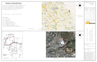
  • 10. PHOTOVOLTAIC AMPACITY & WIRE CALCULATIONS--(3636 MURILLO AVE, SAN JOSE) SHEET PV-10 Solar Module Specifications: Inverter Specifications: Module Model Number: YING-LI YL 230 P-29b Inverter Model Number: SOLECTRIA SGI 500 Module Weight: 43 Pounds Module Length: 65.0'' Width: 39.0'' Depth: 2.0'' Nominal Voltage: 480 Volts (AC) Max Inverter Output Current: 602 Amps Voc (open-circuit Voltage): 37.0 Volts (DC) Vmp (max-power Voltage): 29.5 Volts (DC) Number of Inverters: 5 Isc (short-circuit current): 8.40 Amps Number of Modules per String: 14 Imp (max-power current): 7.80 Amps Total Number of Strings: 936 Mfr Voc Temp Coefficient: -0.37 %/°C Total Number of Modules: 13104 Total System Size: 3013.92 kWstc Maximum PV System Voltage and Current Calculations: Record Low Temp. (°C): 0 ASHRAE Appendix E: SJC Airport Mfr Voc Voltage Correction per Mfr Spec: = x (25°C - Record Low Temp.) + 1 = 1.093 Temp Spec. Maximum PV System Voltage per NEC Voltage Correction Number of Modules in = x Voc x = 566.2 Volts 690.7 per Mfr Spec Series Maximum PV Continuous Current per = 1.25 x Isc x Number of Strings = 9828 Amps NEC 690.8(A)(1) DC Conductor Ampacity Calculation: Number of Strings: 1 Number of Current-Carrying Conductors: 2 Expected Wire Op Temp. (°C): 40 Conduit Fill Correction per NEC 310.15(B)(2)(a): 1.00 Temp. Correction per Table 310.16: 0.91 Circuit Conductor Size: AWG #8 Circuit Conductor Ampacity: 55 Amps Required Circuit Conductor Ampacity = 1.56 x Isc x Number of Strings = 13.2 Amps per 690.8(A)&(B) De-Rated Ampacity of Circuit Temp. Correction per NEC Table Conduit Fill Correction per NEC = x Conductor per NEC Table 310.16 310.16 310.15(B)(2)(a) Length of Conduit Run (ft) 200 x Circuit Conductor Ampacity = 50.1 Amps Voltage Drop 0.62% DC Conductor Ampacity Calculation: Number of Strings: 24 Number of Current-Carrying Conductors: 2 Expected Wire Op Temp. (°C): 40 Conduit Fill Correction per NEC 310.15(B)(2)(a): 1.00 Temp. Correction per Table 310.16: 0.91 Number of Parallel Conductors: 1 Circuit Conductor Size: 500 kcmil Aluminum Circuit Conductor Ampacity: 350 Amps Number of Required Circuit Conductor Ampacity Number of = 1.56 x Isc x / Parallel = 314.5 Amps per 690.8(A)&(B) Strings Conductors De-Rated Ampacity of Circuit Temp. Correction per NEC Table Conduit Fill Correction per NEC = x Conductor per NEC Table 310.16 310.16 310.15(B)(2)(a) Length of Conduit Run (ft) 300 x Circuit Conductor Ampacity = 318.5 Amps Voltage Drop 1.21%
  • 11. AC Conductor Ampacity Calculation (Between Inverter & Transformer): Expected Wire Op Temp. (°C): 40 Number of Current-Carrying Conductors: 3 Temp. Correction per Table 310.16: 0.91 Conduit Fill Correction per NEC 310.15(B)(2)(a): 1.00 Number of Parallel Conductors: 2 Circuit Conductor Size: 500 kcmil Circuit Conductor Ampacity: 430 Amps Required Circuit Conductor Ampacity Maximum Inverter Number of Parallel = 1.25 x / = 376.3 Amps per 690.8(B) Output Current Conductors De-Rated Ampacity of Circuit Temp. Correction per NEC Table Conduit Fill Correction per NEC = x Conductor per NEC Table 310.16 310.16 310.15(B)(2)(a) Length of Conduit Run (ft) 50 x Circuit Conductor Ampacity = 391.3 Amps Voltage Drop 0.34% AC Conductor Ampacity Calculation (Between Transformer & Point of Interconnection): Expected Wire Op Temp. (°C): 30 Number of Current-Carrying Conductors: 3 Temp. Correction per Table 310.16: 1 Conduit Fill Correction per NEC 310.15(B)(2)(a): 1.0 Circuit Conductor Size: AWG #2 MV-105 Circuit Conductor Ampacity: 165 Amps Transformer Required Circuit Conductor Ampacity Maximum Inverter = 1.25 x x 5 Inverters / Voltage of = 144.9 Amps per 690.8(B) Output Power of 500 kW 12.47 kV De-Rated Ampacity of Circuit Temp. Correction per NEC Table Conduit Fill Correction per NEC = x Conductor per NEC Table 310.16 310.16 310.15(B)(2)(a) Length of Wire Run (ft) 2000 x Circuit Conductor Ampacity = 165 Amps Voltage Drop 0.54% Summary for Inverters A, B, C, D: DC Specs: Maximum Short-Circuit Current: 2016.0 Amps Maximum System Voltage: 566.2 Volts Operating Current: 1497.6 Amps Operating Voltage: 413.0 Volts AC Specs: Operating Voltage: 480 Volts Maximum Continuous Current: 602 Amps