An Arduino based smart irrigation control system has been implemented to facilitate the automatic supply of adequate water from a reservoir to domestic crops at all seasons for effective production. The method employed is to continuously monitor the soil moisture level to determine when water is needed in the soil. A pumping mechanism is used to deliver the needed amount of water to the soil through pipes with vent holes. The work was grouped into power supply unit, sensing unit, control unit and pumping unit. A regulated 12 volts power supply unit was built to power the entire system and soil moisture sensor was used to model the electrical resistance of the soil. The control circuit was implemented using Arduino UNO and the pumping unit consists of a submersible low noise micro water pump using a 12 V small dc operated motor. The System was tested and the results obtained showed that this system was able to achieve total removal of human control from irrigation of domestic crops and also optimize the use of water in the process. Yomi Debo-Saiye | Henry. S. Okeke | Peter. O. Mbamaluikem "Implementation of an Arduino-Based Smart Drip Irrigation System" Published in International Journal of Trend in Scientific Research and Development (ijtsrd), ISSN: 2456-6470, Volume-5 | Issue-1 , December 2020, URL: https://www.ijtsrd.com/papers/ijtsrd38157.pdf Paper URL : https://www.ijtsrd.com/engineering/electrical-engineering/38157/implementation-of-an-arduinobased-smart-drip-irrigation-system/yomi-debosaiye
2. International Journal of Trend in Scientific Research and Development (IJTSRD) @ www.ijtsrd.com eISSN: 2456-6470
@ IJTSRD | Unique Paper ID – IJTSRD38157 | Volume – 5 | Issue – 1 | November-December 2020 Page 1131
plants/flowers at ordered interval like office premises,
structures, house gardens, parks, hotels,etc.,isneededusing
the moisture content as a control parameter with Arduino
microcontrollers and C- programming language.
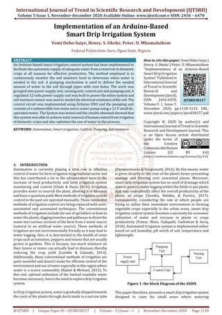
2. DESIGN METHODOLOGY
The Arduino-basedsmartdripirrigationsystem(ASDIS) was
designed to continuously sense the moisture level of the soil
and use its status to determine when to water the soil with
the precise required amount of water and then shuts the
supply of water to the plants when the required level of soil
moisture is achieved. The reference level of soil moisture
content is adjustable for optimal determination of
appropriate soil moisture content requirement for a
particular plant. The block diagram of the system developed
is shown in Figure 1.
3. SYSTEM DESIGN
3.1. Power Supply
Power supply sometimes referred to as an electrical
converter is an electrical device that supplies electrical
power to an electrical circuit and/or load. The powersupply
chosen for this project is 12V. This is because the pump,
relay and Arduino UNO uses 12 V as their input power
supply (Dhakate et al., 2018). The power supply process is
shown below.
Figure 2: Power Supply Process.
3.2. DC Pump
A DC pump uses the current from the power supply to draw
fluid. It has two opening, one opening is used in drawing in
the fluid (water) while the other is used to take out the fluid
(water) draw. The DC pump used for this project is 12 V, 3.6
W (Aslinda &Sheng, 2019).
3.3. Arduino UNO
It is a microcontroller board based on ATmega328P. It has
14 digital input and output pins, 6 Analog pins, a reset
button, a power jack, a USB connection. In this project, the
PIN 8 and PIN 13 were used. PIN 8 was connected to the soil
moisture sensor to extract the state of the soil moisture
information and PIN 13 was connected to the relay for its
operation and control (Parameswaran&Sivaprasath,2016).
3.4. Soil Moisture Sensor
Conventionally, a sensor receives an analog input and
converts it to a digital output. The moisture content is the
physical parameter which is converted into electric signal
and the Soil moisture sensor measures the moisturecontent
of the soil (Sonali, Dinesh & Rojatkar, 2015). The output
terminal of the sensor used are the VCC, GND and the D0
(digital output 0). The D0 takes the digital output from the
sensor and feeds it to the microcontroller.
3.5. Electronic Relay
It is a type of electronic switch that is capable of openingand
closing a circuit without any mechanical movement. The
output of the relay has the NO, NC and COM terminals. The
NO and the COM terminals were used such that if the
operation satisfies the required condition, the NO terminal
closes which allows a flow of current thereby activating the
pump to perform its required operation(Aslinda& Sheng,
2019).
4. Flow Diagram of Proposed System
The operation of ASDIS follows the following flowchart:
Figure 3: the flow Diagram of ASDIS
3. International Journal of Trend in Scientific Research and Development (IJTSRD) @ www.ijtsrd.com eISSN: 2456-6470
@ IJTSRD | Unique Paper ID – IJTSRD38157 | Volume – 5 | Issue – 1 | November-December 2020 Page 1132
4.1. Circuit implementation
The implementation of the electronic circuitry involved physical simulation of the circuit using a breadboardto ensureproper
operation and the implementation of the circuit on a Vero board. The connection of ASDIS is as shown in Figure 4.
Figure 4: The Connection Circuit of ASDIS
From Figure 4, it is seen that the 240 V mains power supply is connected to the 240/12 Vtransformerofthepowersupplyunit.
The channel relay board has three pins on the relay board namely normally open (NO), normally closed (NC) and customary
(C). The most popular pin is linked to NC pin once the relay is off and also to the NO pin once the relay is on.Theinputpin“INP”
receives logic high from Arduino UNO as well as in turn switches around the relay, thus common is linked to NO which turns
the unit on up until the relay is on. The “VCC” and “GND” pins from the relay are linked to 5 V supply and ground
correspondingly. Figure 5 shows the breadboard configuration
RESULTS AND DISCUSSION
The system was tested using a pot of sandy soil as a sample, the result is shown in Figure 5. The ASDIS was also tested in clay
and loamy. Figure 6 and Figure 7 shows the result of ASDIS performance on clay and loamy soil respectively.
Figure 5: Graph of ASDIS performance on sandy soil
Figure 6: Graph of ASDIS performance on clay soil
4. International Journal of Trend in Scientific Research and Development (IJTSRD) @ www.ijtsrd.com eISSN: 2456-6470
@ IJTSRD | Unique Paper ID – IJTSRD38157 | Volume – 5 | Issue – 1 | November-December 2020 Page 1133
Figure 7: Graph of ASDIS performance on loamy soil
In results obtained from the implementation of ASDIS on sandy, clay and loamy soil, it is observed that there is a directly
proportional relationship between the level of soil dryness and the duration in which the water flows during irrigation. The
irrigation water flows for 1.5s, 2.3s and 1.3s in sandy, clay and loamy soil when the soil dryness is 50%. While at 70% soil
dryness the duration of irrigation is 2.5s, 7s and 6s for sand, clay and loamy soil. Then finally when the soil is 100% dry the
duration of irrigation is 4.3s. 13s and 11.5s for sand, clay and loamy soil. The dryer the soil thelongerthedurationof irrigation.
CONCLUSION
Arduino-based smart dripirrigationcontrol systemhasbeen
implemented.Theprototype ofthesystemworkedaccording
to specification and quite satisfactorily. The components for
its implementation are readily available and affordable. The
system helps to eliminate the stress of manual irrigation
control while at the same time preserving the available
water supply. This system improves irrigation efficiency,
hence contributing greatly towards improving the
production of agricultural products. The system was tested
and from the result, the performance of the system can be
adjudged satisfactory. For future work on this project, we
recommend that for a large-scale implementation a more
powerful water pump can be used. Also, IoT technologies
and cameras can be employed to enable remote control and
monitoring of the farm which will help to monitor the soil
moisture and to control the application of water to the
agricultural products thereby saving water and increase
production.
REFERENCES
[1] Aslinda Hassan, Siah Bing Sheng, W. M. S. and N. B.
(2019). Chapter 1. An Automated Irrigation System
Using Arduino Microcontroller, 1908(January), 2–6.
[2] Chate, B. K., & Rana, J. (2016). SMART IRRIGATION
SYSTEM USING RASPBERRY PI. International
Research Journal of Engineering and Technology, 3(5),
247 - 249.
[3] Dhakate, K., Kambe, S., & Meshram, S. (2018). A
Review on Arduino Based Smart Irrigation System.
4(2), 623–630.
[4] Londhe, G., & Galande,S.(2014).AutomatedIrrigation
System ByUsingARMProcessor.InternationalJournal
of Scientific Research Engineering & Technology, 3(2),
254-258
[5] Muñoz-Carpena, R., & Dukes, M. D. (2015). Automatic
irrigation based on soil moisture for vegetable crops.
Nutrient Management of Vegetable and Row Crops
Handbook, 173.
[6] Parameswaran, G., & Sivaprasath, K. (2016). Arduino
Based Smart Drip Irrigation System Using Internet of
Things. International Journal of Engineering Science,
5518(5), 5518–5521.
https://doi.org/10.4010/2016.1348
[7] Pawar, R., Wani, K., Vadapalli, L., Yashshree, P., &
Suraj, P. (2018). An Astute Irrigation System With
Crop Management And Marketing. International
Journal of Computational Intelligence & IoT, 2(3).
[8] Sonali D. Gainwar, DineshV.Rojatkar.Soil Parameters
Monitoring With AutomaticIrrigationSystem.IJSETR,
Volume 4, Issue 11,November 2015
[9] Swetha, R. N., Nikitha, J., & Pavitra, B. (2017). SMART
DRIP IRRIGATION SYSTEM FOR CORPARATE
FARMING-USING INTERNET OF THINGS.
International Journal of Creative Research Thoughts,
5(4), 1846 - 1851.