Ohnmar Win
The design of filter has become the core issues of the signal processing. Generally speaking, filter can be divided into analog filter and digital filter. Today, the development of analog filter has been more mature. However, digital filter has many advantages, such as higher stability, higher precision. With the development of digital technology, using digital technology to realize filter function is widely used. A MATLAB based digital filter design procedure designs the filter and applied to the voice signal. In this project, the recorded speech with simulated noises is processed. The speech signal “I Love Electronics†is taken as the input signal. AWGN is added with the input speech signal. Two types of IIR filters Butterworth and Chebyshev are designed and are applied to the noisy speech signal. The magnitude response, phase response, impulse response and order of the filters are generated. Ohnmar Win "IIR Filter Design for De-Nosing Speech Signal using Matlab" Published in International Journal of Trend in Scientific Research and Development (ijtsrd), ISSN: 2456-6470, Volume-3 | Issue-3 , April 2019, URL: https://www.ijtsrd.com/papers/ijtsrd21576.pdf
2. International Journal of Trend in Scientific Research and Development (IJTSRD) @ www.ijtsrd.com eISSN: 2456-6470
@ IJTSRD | Unique Paper ID - IJTSRD21576 | Volume – 3 | Issue – 3 | Mar-Apr 2019 Page: 5
III. SYSTEM STRUCTURE
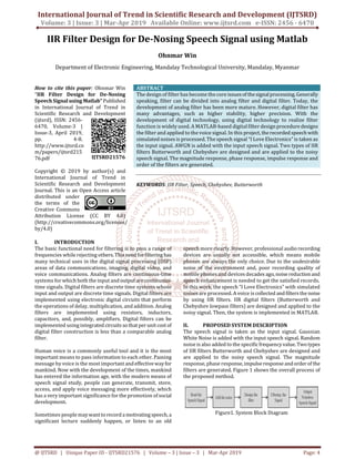
The system structure will be shown in details below. Figure
2 shows the flow diagram of the proposed system.
Figure2. Flow Diagram of the Proposed System
The function of system is to obtain the samples from voice
card. Data analyses parts mainly have functions below:
Collect the speech signal
Display voice signals frequency domain figure and time
domain figure.
Put a random noise signal by using MATLAB into the
original signal
Design IIR filter to filter the noise
Noisy signal through the filters and
Replay the voice
The IIR filters are designed by following procecures:
Step1. Using the prescribed specifications, calculate
minimum order of filter (n) and cutoff frequencies
ωn for an analog filter.
Step2. Form the normalized transfer function for n order.
Step3. Apply the analog-filter transformation.
Step4. Apply the bilinear transformation
This work considers the details of the above design
procedure with the boundary frequency in band pass of this
filter is 300Hz, the cutoff frequency in stop band is 500Hz,
sampling frequency is 8000Hz, the maximum attenuation in
band pass is 1dB, the minimum attenuation in stop band is
50dB.
IV. FILTER DESIGN SIMULATION PARAMETERS
Digital IIR filters have been derived from their analog
counterparts. Classical prototype analog filters are
Butterworth, Chebyshev I, Chebyshev II and Elliptic.
Parameters required designing IIR filters are sampling
frequency, Pass band edge frequency, Stop band edge
frequency, Pass band ripples and Stop band ripples. Using
these parameters, magnitude response, phase response,
impulse response and order of the filter can be generated.
In this work, the IIR Filter is designed that satisfy the
following specifications:
frequency at the start of the pass band in normalized
frequency units - 300Hz (0.075*pi)
frequency at the end of the stop band in normalized
frequency units - 500Hz (0.125*pi)
Passband ripple in decibels - 1
Stopband attenuation in decibels - 50
Sampling Frequency in Hz – 8000 Hz
V. FILTER DESIGN SIMULATION RESULTS
In this work, IIR lowpass filter Butterworth and Chebyshev
are designed by using the design parameters in the above
section.
A. Butterworth Filter
The transfer function for Butterwoth filter is as follow:
z13 - 10.89 z12 + 54.9 z11 - 169.6 z10 + 357.9 z9 - 545.3 z8 +
616.8 z7 - 524.5 z6 + 335.2 z5 - 159 z4 + 54.41 z3 - 12.72 z2 +
1.821z - 0.1205
--------------------------------------------------------------------
8.379×10⁻¹³ z13 + 1.09×10⁻¹¹ z12 + 6.531×10⁻¹¹ z11 +
2.398×10⁻¹⁰ z10 + 5.986×10⁻¹⁰ z9 + 1.079×10-09 z8 +1.436×10-
09 z7 + 1.439×10-09 z6 + 1.078×10-09 z5 + 5.994×10⁻¹⁰ z4 +
2.395×10⁻¹⁰ z3 + 6.539×10⁻¹¹ z2 + 1.089×10⁻¹¹ z + 8.383×10⁻¹³
Figure3. Magnitude Response of Butterworth Lowpass
Filter
Figure4. Pole/Zero Plot of Butterworth Lowpass Filter
Figure 3 is Butterworth lowpass filter; it can be seenthatthe
cutoff frequency is 300 Hz (0.075*pi), which means the
performance of low pass filter is good. It has a perfect cutoff
frequency that can filter all high components.
3. International Journal of Trend in Scientific Research and Development (IJTSRD) @ www.ijtsrd.com eISSN: 2456-6470
@ IJTSRD | Unique Paper ID - IJTSRD21576 | Volume – 3 | Issue – 3 | Mar-Apr 2019 Page: 6
Figure 4 shows the pole/zero plot of the proposed designed
Butterworth lowpass filter. Allpoles areintheunitcircleand
all zeros are on the unit circle. Therefore the filter is stable.
The simulation shows that the designed filter is stable.
B. Chebyshev Filter
The transfer function for Chebyshev filter is as follow:
z7 - 6.688 z6 + 19.26 z5 - 30.98 z4 + 30.03 z3 - 17.55 z2 +
5.727z - 0.8045
-----------------------------------------------------------------------
8.746×10-09z7 + 6.122×10-08z6 + 1.837×10-07z5 + 3.061×10-
07z4 + 3.061×10-07z3 + 1.837×10-07z2 + 6.122×10-08z +
8.746×10-09
Figure5. Magnitude Response of Chebyshev Lowpass Filter
Figure 5 is Chebyshev lowpass filter; it can be seen that the
cutoff frequency is 300 Hz (0.075*pi). It has aperfect cutoff
frequency that can filter allhigh components. Figure6 shows
the pole/zero plot of the proposed designed Butterworth
lowpass filter. All poles are in the unit circle and all zeros are
on the unit circle. Therefore the filter is stable.
Figure6. Pole/Zero Plot of Chebyshev Lowpass Filter
VI. STEP BY STEP TESTING RESULTS
The simulation results of the proposed methods are shown
in the below figures.
A. Collection of Voice Signal
Collect the digital signals by using the sound card on pc and
WINDOWS operating system. Microphone is already built in
in laptop. So it isn’t needed to add the microphone for
recording the voice. For recording the voice the
“recording.m” program is run and said “I love electronics”
and then stop recording. The length of the recording voice is
3 sec in this work. After recording the voice, the speech we
have made is replayed.
Figure7. Original Speech in Time Domain
The Figure 7 shows the original signal representation of
speech signal which was spoken by a woman. The voice is
recorded and it is stored as a wave file for further usage in
MATLAB.
Figure8. Original Speech in Frequency Domain
B. Noising Signal
There are some common kinds of noise, such as periodic
noise, pulse noise, wideband noise, lombard effect and etc.
Due to the complexity of possible noise, the comparably
simple one, white noise, is selected to simulate the noise in
speech. The Figure 9 shows the noisy input signal
representation which is treated as the original signal. Noisy
speech signal is the AWGN added speech signal.
Figure9. Noisy speech in Time Domain, SNR=5 dB
4. International Journal of Trend in Scientific Research and Development (IJTSRD) @ www.ijtsrd.com eISSN: 2456-6470
@ IJTSRD | Unique Paper ID - IJTSRD21576 | Volume – 3 | Issue – 3 | Mar-Apr 2019 Page: 7
Figure10. Noisy speech in Frequency Domain, SNR=5 Db
C. Filtering Speech Signal
In this work, the two filter design Butterworth and
Chebyshev are implemented. Figure 11 and 12 shows the
filtering results with Butterworth filter.
Figure11. Filtering Speech in Time Domain (Butterworth)
Figure12. Filtering Speech in Frequency Domain
(Butterworth)
Figure 13 and 14 are described the filtering results with
Chebyshev filter. We applied this filter tothenoised signal;it
can be seen that the high component has been removed.
Figure13. Filtering Speech in Time Domain (Chebyshev)
Figure14. Filtering Speech in Frequency Domain
(Chebyshev)
And the waveforms width isreduced becauseoftheremoved
noise. Then when playback the sound it is heard the noise
sound is lowering than before.
VII. CONCLUSION
In this work, two types of IIR filter are applied for noise
removal from speech signal. Noisy signal with Gaussian
white noise and random noise was prepared by addingnoise
with clean signal using MATLAB software at 5dB SNR levels.
The proposed digital IIR filter for speech signals has been
designed. In this project, DSP tools from class like time
domain analysis and Fast Fourier Transform are used in
speech analysis. “Fdatool” are used to analyze the filter
design. Two different filters are applied to originalspeech to
reduce noise.
In this work, voice card and microphone that built in laptop
are used for voice signal recording. The voice signal analysis
and process can be done well using the strong data
processing function in MATLAB.
5. International Journal of Trend in Scientific Research and Development (IJTSRD) @ www.ijtsrd.com eISSN: 2456-6470
@ IJTSRD | Unique Paper ID - IJTSRD21576 | Volume – 3 | Issue – 3 | Mar-Apr 2019 Page: 8
REFERENCES
[1] Y. LI and M. GUO, “Audio Data Acquisition System Based
on MATLAB”, Journal of Audio Engineering,vol31, no.1,
pp: 38-48, May 2007.
[2] H. Wang, G. Wang, X Jin and N Bai “Application of data
acquisition system based on sound card and MATLAB in
Young modulus measurement”, Journal of Physics
Experimentation, vol 4, no.1, pp: 205-246, April 2005.
[3] M. D. Lutovac, D.V. Tošić and B. L. Evans. “Filter Design
for Signal Processing Using MATLAB andMathematica”,
4sted. Beijing: House of Electronics Industry, 2004.
[4] B.A.Shenoi, “Introduction to Digital Signal Processing
and Filter Design”, 1st ed. Canada: John Wiley & Sons,
2006.