Analysis of Spoiler Using Wind Tunnel Experiment
•
0 likes•204 views

As in today's world the use of petroleum products is increasing, it leads to more pollution and degradation of our environment. This work will investigate the result of an experimental study carried out to determine the performance of a car spoiler (inverted aerofoil) and study the pressure difference produced by it and also prove the transit theory of pressure difference over an aerofoil. It is used widely in formula racing cars. The various angles of attack and there effects on pressure differences will be measured. The performance parameters are to be investigated and observed. Index Terms: W

Recommended
Recommended
More Related Content
What's hot
What's hot (20)
Viewers also liked
Viewers also liked (20)
Similar to Analysis of Spoiler Using Wind Tunnel Experiment
Similar to Analysis of Spoiler Using Wind Tunnel Experiment (20)
Recently uploaded
Recently uploaded (20)
Analysis of Spoiler Using Wind Tunnel Experiment
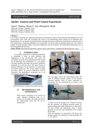
- 1. Jesal J. Thakkar et al. Int. Journal of Engineering Research and Applications www.ijera.com ISSN: 2248-9622, Vol. 5, Issue 9, (Part - 2) September 2015, pp.39-42 www.ijera.com 39 | P a g e Spoiler Analysis and Wind Tunnel Experiment Jesal J. Thakkar, Harsh V. Jani, Dhrupad R. Sheth BITS Edu. Campus, Vadodara, India BITS Edu. Campus, Vadodara, India BITS Edu. Campus, Vadodara, India Abstract As in today's world the use of petroleum products is increasing, it leads to more pollution and degradation of our environment. This work will investigate the result of an experimental study carried out to determine the performance of a car spoiler (inverted aerofoil) and study the pressure difference produced by it and also prove the transit theory of pressure difference over an aerofoil. It is used widely in formula racing cars. The various angles of attack and there effects on pressure differences will be measured. The performance parameters are to be investigated and observed. Index Terms: Wind tunnel experiment, spoiler, airfoil, transit theory, computational fluid dynamics, ansys I. INTRODUCTION: As in today's world the use of petroleum products is increasing, it leads to more pollution and degradation of our environment. This work will investigate the result of an experimental study carried out to determine the performance of a car spoiler (inverted aerofoil) and study the pressure difference produced by it and also prove the transit theory of pressure difference over an aerofoil. It is used widely in formula racing cars. The various angles of attack and there effects on pressure differences will be measured. The performance parameters are to be investigated and observed. CROSS SECTION OF A SPOILER (INVERTED AIR FOIL) II. METHODOLOGY AND EXPERIMENT: Wind tunnel experiment was carried out under subsonic conditions with an air velocity of 16 kmph. The following shows the experimental setup and the use of anemometer. The next figure shows the experimental setup. We used 11 different pressure points on the aerofoil (inverted spoiler). Each of them connected to piezometer for the measurement of positive and negative pressure. To start, we set the aerofoil at 0°. Further, we found out the pressures at different pressure points by acknowledging the height differences in manometer. We also carried out experiment using a smoke generator to see the exact streamlines of air around the aerofoil. From the pressure we could derive the forces and pressure graph. We repeated the same procedure for 5°, 10° and 15°. RESEARCH ARTICLE OPEN ACCESS
- 2. Jesal J. Thakkar et al. Int. Journal of Engineering Research and Applications www.ijera.com ISSN: 2248-9622, Vol. 5, Issue 9, (Part - 2) September 2015, pp.39-42 www.ijera.com 40 | P a g e III. CALCULATIONS: Gauge Pressure Calculation = ρ*g*Δh N/m² Absolute pressure Calculation = Atmospheric pressure + gauge pressure = 101325 N/m² + ρ*g*Δh N/m² Force (F₁,₂,₃…) = Absolute pressure N/m² * Area(A₁,₂,₃…) N Net Force Fɴ = Resultant of forces F₁,₂,₃…….N. (Resultant force –direction) • Drag force (Fh) = F₁cosθ₁ - F₂cosθ₂ - F₃cosθ₃ + F₄cosθ₄ + F₅ cosθ ₅ + F₆ cosθ ₆ + F₇ cosθ ₇ + F₈ cosθ ₈ - F₉ cosθ ₉ - F₁₀ cosθ ₁₀ + F₁₁ cosθ₁₁ • Lift force (Fv) = -F₁sinθ₁ + F₂sinθ₂ + F₃sinθ₃ + F₄sinθ₄ + F₅ sinθ ₅ + F₆ sinθ ₆+F₇ sinθ ₇ + F₈ sinθ ₈ + F₉ sinθ ₉ + F₁₀ sinθ ₁₀ + F₁₁ sinθ₁₁ Resultant force (Fʀ)(N) = sqrt( Fh² + Fv² ) Tanθ = Fv / Fh Pressure points wrt. Center of gravity IV. ANALYTICAL RESULTS: 98 100 102 104 0 5 10 15 height(mm) Pressure points Manometric height 0° 5° 10° 15° Pressure points 1 2 3 4 5 6 7 8 9 10 11 Angles(point forces)◦ 0 60 84 90 83 66 90 90 83 78 86
- 3. Jesal J. Thakkar et al. Int. Journal of Engineering Research and Applications www.ijera.com ISSN: 2248-9622, Vol. 5, Issue 9, (Part - 2) September 2015, pp.39-42 www.ijera.com 41 | P a g e 900 1000 1100 0 5 10 15 gaugepressure(N/m²) pressure points Gauge Pressure 0◦ 5◦ 10◦ 15◦ 100000 105000 0 5 10 15 absolutepressure(N/m²) pressure points Absolute pressure 0◦ 5◦ 10◦ 15◦ V. FINAL FORCE RESULT TABLE: VI. COMPUTATIONAL RESULTS: As the airfoil we used was of unknown dimensions, we had to reproduce the airfoil in solid works to carry out the computational fluid analysis. For achieving this, we had to plot the X-Y points on the graph by extrapolating the coordinate points and using these same points for producing the exact profile on Solidworks. Following are the basic condition for our aerofoil analysis: The conditions at boundary of the designed airfoil is NO-SLIP. Reference pressure is taken as 0 bar Conditions for sidewalls for airfoil is FREE- SLIP. Meshing is compiled using mesh sweep method. The mesh type is hexahedral and total no. of nodes per element is 8. The inlet velocity acting in the positive x direction is 18 kmph Total number of nodes = 1097693 Total number of elements = 1053400 Profile generation in solid works
- 4. Jesal J. Thakkar et al. Int. Journal of Engineering Research and Applications www.ijera.com ISSN: 2248-9622, Vol. 5, Issue 9, (Part - 2) September 2015, pp.39-42 www.ijera.com 42 | P a g e The above shown is the hexahedral meshing of the computational domain around the airfoil using sweep method Pressure graph around the aerofoil Streamline around the aerofoil Velocity graph around the aerofoil References (Book style with paper title and editor) [1.] R.S Khurmi, J.K Gupta “Thermal Engineering” A textbook for the students of B.Sc. Engg., UPSC (Engg. Services), Section 'B' of AMIE (I) and Diploma Courses. [2.] J.P Hadiya, “Fluid Power Mechanics,” books India publications fourth edition. [3.] J.P Hadiya, H.J Kataria “Engineering Thermodynamics,” books India publications fourth edition. [4.] Dr. R.K Bansal “Fluid Mechanics” ISBN :978-81-318-0814-6 Edition : Sixth, 2015 [5.] R.K Rajput “ Heat and Mass Transfer” Edition : Fifth Edition 2013 [6.] Research paper Ishan M Shah, K.H Thakkar, S.A Thakkar, Bhavesh Patel International journal of Engineering Research and Applications (IJERA) ISSN: 2248-9622 Vol. 3, Issue 4, Jul-Aug 2013, pp.2094-2103 [7.] www.airfoiltools.com [8.] www.wikipedia.com [9.] www.xfoils.com [10.] www.sciencedirect.com [11.] www.exp-aircraft.com [12.] www.autoevolution.com [13.] www.design-real.com