Dynamic Analysis of Rotating Shaft Subjects to Slant Crack with Experimentation and ANSYS Validation
•
1 like•414 views

The paper contents the dynamic study of rotating shaft with slant crack on surface of shaft. Slant cracks are prepared artificially on surface of shaft with material EN8. In this study, crack location taken on shaft 150 mm from motor side and also for effective study healthy shaft of EN8 material is taken. Experimental results are taken with the help of FFT analyzer. Analysis is carried out from these results and finally these results are validated in FEA software i. e. ANSYS14 software. These validated results with graphs are explained in this paper. The experimentation is also done on healthy shaft of EN8 material for analysis. This paper mainly focused on validation of experimental results with ANSYS software.

Recommended
Recommended
More Related Content
What's hot
What's hot (13)
Viewers also liked
Viewers also liked (20)
Similar to Dynamic Analysis of Rotating Shaft Subjects to Slant Crack with Experimentation and ANSYS Validation
Similar to Dynamic Analysis of Rotating Shaft Subjects to Slant Crack with Experimentation and ANSYS Validation (20)
Recently uploaded
Recently uploaded (20)
Dynamic Analysis of Rotating Shaft Subjects to Slant Crack with Experimentation and ANSYS Validation
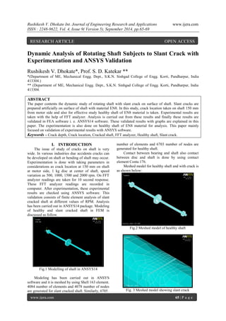
- 1. Rushikesh V. Dhokate Int. Journal of Engineering Research and Applications www.ijera.com ISSN : 2248-9622, Vol. 4, Issue 9( Version 5), September 2014, pp.65-69 www.ijera.com 65 | P a g e Dynamic Analysis of Rotating Shaft Subjects to Slant Crack with Experimentation and ANSYS Validation Rushikesh V. Dhokate*, Prof. S. D. Katekar ** *(Department of ME, Mechanical Engg. Dept., S.K.N. Sinhgad College of Engg. Korti, Pandharpur, India 413304.) ** (Department of ME, Mechanical Engg. Dept., S.K.N. Sinhgad College of Engg. Korti, Pandharpur, India 413304. ABSTRACT The paper contents the dynamic study of rotating shaft with slant crack on surface of shaft. Slant cracks are prepared artificially on surface of shaft with material EN8. In this study, crack location taken on shaft 150 mm from motor side and also for effective study healthy shaft of EN8 material is taken. Experimental results are taken with the help of FFT analyzer. Analysis is carried out from these results and finally these results are validated in FEA software i. e. ANSYS14 software. These validated results with graphs are explained in this paper. The experimentation is also done on healthy shaft of EN8 material for analysis. This paper mainly focused on validation of experimental results with ANSYS software. Keywords – Crack depth, Crack location, Cracked shaft, FFT analyzer, Healthy shaft, Slant crack. I. INTRODUCTION The issue of study of cracks on shaft is very wide. In various industries due accidents cracks can be developed on shaft or bending of shaft may occur. Experimentation is done with taking parameters in considerations as crack location at 150 mm on shaft at motor side, 1 kg disc at center of shaft, speed variation as 500, 1000, 1500 and 2000 rpm. On FFT analyzer readings are taken for 10 second response. These FFT analyzer readings are recorded in computer. After experimentation, these experimental results are checked using ANSYS software. This validation consists of finite element analysis of slant cracked shaft at different values of RPM. Analysis has been carried out in ANSYS14 package. Modeling of healthy and slant cracked shaft in FEM is discussed as follow. Fig.1 Modelling of shaft in ANSYS14 Modeling has been carried out in ANSYS software and it is meshed by using Shell 163 element. 4084 number of elements and 4078 number of nodes are generated for slant cracked shaft. Similarly, 6705 number of elements and 6703 number of nodes are generated for healthy shaft. Contact between bearing and shaft also contact between disc and shaft is done by using contact element Conta 176. Meshed model for healthy shaft and with crack is as shown below: Fig.2 Meshed model of healthy shaft Fig. 3 Meshed model showing slant crack RESEARCH ARTICLE OPEN ACCESS
- 2. Rushikesh V. Dhokate Int. Journal of Engineering Research and Applications www.ijera.com ISSN : 2248-9622, Vol. 4, Issue 9( Version 5), September 2014, pp.65-69 www.ijera.com 66 | P a g e Meshing density was increased at slant crack portion by refining elements. In boundary conditioning, movement of shaft in X direction is made zero. So that, to and fro motion of shaft is restricted. Assembly of four components in ANSYS software is done. Two bearings, one disc and shaft are defined as components made up of nodes. Nodal rotation along X axis is applied at 500rpm, 1000rpm, 1500rpm and 2000rpm. While applying rpm it was converted to rad/sec. Explicit dynamic analysis has been carried out. Response of the assembly was obtained in 0.01 sec. Analysis was carried out in 500 number of sub-steps. Response at each node was taken into consideration. Node at the top of bearing surface was selected for getting accurate response. Results were obtained in frequency domain. Because during experimentation results were obtained by mounting probe of FFT analyzer at the same location. Node 362 lies at center of top of surface of bearing. Results validation is done for EN8 material at different values of RPM. The set up representation of experimentation is as shown in below fig.4. This fig.4 shows top view representation of arrangement made for experimentation. Fig.4 Top view arrangement for Experimental setup II. RESULTS AND DISCUSSION The below figures shows the results plotted with graphical representation for experimentation of analysis of rotating shaft and also graphs plotted for validation of these results with ANSYS14 software. For slant crack location on shaft surface at 150 mm from motor side. With speed variations as 500, 1000, 1500 and 2000 rpm with 1kg disc is mounted at center of shaft for loading condition. Response received for these conditions are acceleration vs. frequency. Results are plotted for healthy shaft of EN8 material and also for slant cracked shaft at location at 150 mm on shaft of EN8 material. These plotted results are discussed later with tabulation. Fig.5 Response of healthy shaft at 500 rpm for FFT analyzer. Fig.6 Response of healthy shaft at 500 rpm for ANSYS14 Fig.7 Response of healthy shaft at 1000 rpm for FFT analyzer. Fig.8 Response of healthy shaft at 1000 rpm for ANSYS14
- 3. Rushikesh V. Dhokate Int. Journal of Engineering Research and Applications www.ijera.com ISSN : 2248-9622, Vol. 4, Issue 9( Version 5), September 2014, pp.65-69 www.ijera.com 67 | P a g e Fig.9 Response of healthy shaft at 1500 rpm for FFT analyzer. Fig.10 Response of healthy shaft at 1500 rpm for ANSYS14 Fig.11 Response of healthy shaft at 2000 rpm for FFT analyzer. Fig.12 Response of healthy shaft at 2000 rpm for ANSYS14 Table No.1 Tabulated results for EN8 healthy shaft Speed rpm Experimental results(m/s2) ANSYS results(m/s2) Percentage error(%) 500 0.1715 0.1702 0.758017 1000 1.3967 1.3903 0.458223 1500 4.8139 4.9320 -2.45331 2000 1.1869 1.1901 -0.26961 All the above figures shows the response diagrams for various speeds and its validation with ANSYS software. It is observed that there is 0.7580 maximum percentage deviations in results of experimentation and results of simulation for healthy shaft. Also, with experimentation it was observed that highest amplitude is achieved at speed of 1500 rpm. At 500 rpm response was low it increases with increase in speed. After 1500 rpm speed for 2000 rpm amplitude reduces. Now, below figures shows the responses for slant cracked shaft at location of 150 mm on EN8 material. Fig.13 Response of slant cracked EN8 shaft at 150mm at 500 rpm for FFT analyzer. Fig.14 Response of slant cracked EN8 shaft at 150mm at 500 rpm for ANSYS14 Fig.15 Response of slant cracked EN8 shaft at 150mm at 1000 rpm for FFT analyzer.
- 4. Rushikesh V. Dhokate Int. Journal of Engineering Research and Applications www.ijera.com ISSN : 2248-9622, Vol. 4, Issue 9( Version 5), September 2014, pp.65-69 www.ijera.com 68 | P a g e Fig.16 Response of slant cracked EN8 shaft at 150mm at 1000 rpm for ANSYS14 Fig.17 Response of slant cracked EN8 shaft at 150mm at 1500 rpm for FFT analyzer. Fig.18 Response of slant cracked EN8 shaft at 150mm at 1500 rpm for ANSYS14 Fig.19 Response of slant cracked EN8 shaft at 150mm at 2000 rpm for FFT analyzer. Fig.20 Response of slant cracked EN8 shaft at 150mm at 2000 rpm for ANSYS14 Table No.2 Tabulated results for EN8 slant cracked shaft at location 150mm Speed rpm Experimental results(m/s2) ANSYS results(m/s2) Percentage error(%) 500 0.2132 0.2205 -3.42402 1000 1.0201 1.0421 -2.15665 1500 3.5087 3.4991 0.273606 2000 1.3010 1.3223 -1.6372 It is observed that there is 0.2736 maximum percentage deviations in results of experimentation and results of simulation for Cracked shaft at location 150mm of EN8. With comparison to results to healthy shaft of EN8 material we can say that amplitude is increased for the speed of 500 rpm and amplitude is decreased for the speed of 1500 rpm. We can say with these two comparisons that there is variation in amplitude for healthy and slant cracked shaft. Amplitude in increases for small speed and it is decreases for increased speed. III. CONCLUSION In the present study, dynamic analysis of healthy and slant cracked shaft having EN8 material is done. The scope of this work is limited to measurement of amplitudes of vibrations of rotating shaft with slant crack on surface at various speeds and different locations. Focus is not on the defects on the bearing. Study is done with variation of speed and 1 kg load experimentally and validated with ANSYS14 FEA software. The validated result also shows good percentage of deviations. The response of both healthy and slant cracked shaft at 150mm for higher amplitude is at 1500rpm. Up to 1500rpm amplitude increases and it comes low after 1500 rpm. The rate of increase of amplitude is lower for the speed 500 and 1000 rpm and it is increased at 1500rpm. In present cases in this paper, at 500 and 2000 rpm amplitude in slant cracked shaft than healthy shaft is increased little and that is decreased little for 1000rpm and 1500rpm.
- 5. Rushikesh V. Dhokate Int. Journal of Engineering Research and Applications www.ijera.com ISSN : 2248-9622, Vol. 4, Issue 9( Version 5), September 2014, pp.65-69 www.ijera.com 69 | P a g e IV. ACKNOWLEDGEMENTS The authors would like to acknowledge the Excel Engineers Ltd, Sangali (India) for providing the test shaft samples required for the experimentation. The gratitude is also extended to SKN Sinhgad COE, Pandharpur for providing facilities during experimentation. Authors would also thankful to Prof. P.P. Kulkarni S.K.N Sinhgad COE, Pandharpur for guidance to handling ANSYS14 FEA software. REFERENCES Journal Papers: [1] Qinkai Han, Jingshan Zhao, Fulei Chu, “Dynamic analysis of a geared rotor system considering a slant crack on the shaft”, (Journal of Sound and Vibration, vol.331 (2012), pp. 5803–5823) [2] R. Ramezanpour, M. Ghayour, S. Ziaei-Rad, “Dynamic behavior of Jeffcott rotors with an arbitrary slant crack orientation on the shaft”, (Applied and Computational Mechanics, vol.6 (2012), pp.35–52) [3] Yanli Lin, Fulei Chu, “The dynamic behavior of a rotor system with a slant crack on the shaft”, (Mechanical Systems and Signal Processing, vol.24 (2010), pp.522– 545) [4] A.S. Sekhar, “Multiple cracks effects and identification”, (Mechanical Systems and Signal Processing vol.22 (2008) pp.845– 878) [5] Ashish K. Darpe, “Coupled vibrations of a rotor with slant crack”, (Journal of Sound and Vibration vol.305 (2007) pp.172–193) [6] J.J. Sinou, A.W. Lees, “The influence of cracks in rotating shafts”, (Journal of Sound and Vibration vol.285 (2005) pp.1015-1037) [7] A. S. Sekhar, A. R. Mohanty, S. Prabhakar, “Vibrations of cracked rotor system: transverse crack versus slant crack”, (Journal of Sound and Vibration vol.279 (2005), pp 1203–1217) [8] D. P. Patil, S.K. Maiti, “Detection of multiple cracks using frequency measurements”, (Engineering Fracture Mechanics vol.70 (2003) pp.1553–1572) [9] A. S. Sekhar, P. Balaji Prasad, “Dynamic analysis of a rotor system considering a slant crack in the shaft”, (Journal of Sound and Vibration, vol.208 (3) (1997), pp. 457- 474) Books: [10] S. S. Rao, “mechanical vibrations”, Pearson Higher Education, 5th Revised Edition, (2011). [11] V.P. Singh, “mechanical vibrations”, Dhanpat Rai Publication, 3rd Edition, (2011). Theses: [12] Rajdeep Singh, Vibration Based Analysis of Defects in Rotating Shafts, masters degree diss., Department of Mechanical Engg., Thaper University, Patiala, July 2011.