Design of a Multispeed Multistage Gearbox
•
0 likes•118 views

This document describes the design of a 4-speed 2-stage gearbox using spur gears. The gearbox is designed to transmit 0.34 kW of power with speed steps of 1100 rpm, 1603 rpm, 2335 rpm, and 3400 rpm. The gearbox uses a sliding mesh design with splined shafts to allow gears to slide and mesh. Calculations are shown for determining the number of teeth on each gear, gear dimensions, shaft dimensions, key and spline dimensions, and bearing selection. A kinetic diagram is developed and gear dimensions are verified using stress-strain analysis. The designed gearbox is intended for low to medium power applications in light machinery.

Recommended
More Related Content
What's hot
What's hot (19)
Viewers also liked
Viewers also liked (20)
Similar to Design of a Multispeed Multistage Gearbox
Similar to Design of a Multispeed Multistage Gearbox (20)
Recently uploaded
Recently uploaded (20)
Design of a Multispeed Multistage Gearbox
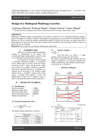
- 1. Aishwarya Dhawad.et. al. Int. Journal of Engineering Research and Applications www.ijera.com ISSN: 2248-9622, Vol. 6, Issue 5, (Part - 4) May 2016, pp.54-57 www.ijera.com 54 | P a g e Design of a Multispeed Multistage Gearbox Aishwarya Dhawad1 , Dushyant Moghe2 , Gautam Susheel3 , Gaurav Bhagat4 1,2,3,4 Student, Mechanical Engineering, Maharashtra Institute Of Technology, Maharashtra, India ABSTRACT Whenever a frequent change in speed/torque at the output is required, we use multispeed multistage gearbox. Aim of the paper is to design a 4 speed 2 stage gearbox using spur gears so as to make the transmission highly efficient as well as to keep the gearbox economically feasible. Cad plot for the same was plotted and stress- strain analysis for each was done. The paper includes all the calculations and verification of those at places to justify the success of design. Keywords- kinetic diagram, ray diagram, sliding mesh, spline shaft. I. INTRODUCTION Whenever we require sudden and frequent changes to speed/torque at the output ,then conventional single speed gearbox cannot be used as it would make the gearbox bulky and heavy. In this paper an attempt is made to design a multistage multispeed gearbox A mechanical device which helps to provide speed and torque conversions from a input rotating power source (e.g. a motor) to an output is termed as a gearbox. The utmost important function of a gearbox is to transmit power according to the required output element from a constantly varying input power source. A sliding mesh gearbox is used. The splined shaft is used so as to enable the gears to slide on the shaft and mesh on with the gear pairs. II. DESIGN OF GEARBOX:- 1.1 Specifications :- Power transmitted : - .340Kw Minimum output speed : - 1100rpm Maximum output speed : - 3400rpm Motor speed (input speed) : - 3000rpm Number of speed steps : - 4 1.2 Geometric progression ratio :- ∅ = 𝒏𝒎𝒂𝒙 𝒏𝒎𝒊𝒏 𝟏 𝒛−𝟏 = 1.457 The spindle speeds obtained are as follows:- Speed step Spindle speed Expression Value 1 n1=nmin 1100rpm 2 n2=n1* ∅ 1603rpm 3 n3=n2* ∅ 2335rpm 4 n4=n3* ∅ 3400rpm 1.3 Number of stages :- N= 𝑙𝑜𝑔𝑧 𝑙𝑜𝑔 𝑝 = 2 From the above we obtain a 2 stage gearbox with each stage of 2 speed steps. We obtain 2 structural formulas and their structure diagram is plotted so as to select the optimum one which is obtained by mode method of optimization Z=2(1).2(2) & Z=2(2).2(1) (a) Z=2(2).2(1) (b) Z=2(1).2(2) Structu re Diagra m Nodes on Shaft ∑Node Numbe rs Remar ks 1S T 2N D 3R D A 2. 5 3. 5 4 10 Not optimu m B 2. 5 3 4 9.5 Optimu m Structure diagram RESEARCH ARTICLE OPEN ACCESS
- 2. Aishwarya Dhawad.et. al. Int. Journal of Engineering Research and Applications www.ijera.com ISSN: 2248-9622, Vol. 6, Issue 5, (Part - 4) May 2016, pp.54-57 www.ijera.com 55 | P a g e 2.4 Kinematic arrangement and calculation of number of teeth:- Now for actual number of teeth of gear, Assume d Z1i Z1o=1.207 Z1i Z2i=1.207Z 2i Z20=.82 8Z2i Z1i+ Z1o 18 21.73 21.73 18 39.7 3 19 22.93~23 22.93~23 19 41.9 3 Similarly after performing similar calculations for 2nd and 3rd shaft, we get number of teeth as Z1i=19; Z10=23; Z2i=23; Z2o=18; Z3i=20; Z3o=29 ; Z4i=29 ; Z4o=20 . 2.5 Design of gears:- Material selected is alloy steel 40Ni2CrMo28. Sut=1550 𝑁 𝑚𝑚 2 Standard tooth system of 20° full depth involute is selected. B.H.N=600. Lewis Buckingham method of gear design is used. Individually each gear pair is initially designed and later analyzed to ensure that the gears fulfill the design criterion. 2.5.1 Gear for stage 1:- As the material for both gear and pinion is same, from Lewis equation 𝑦 = .484 − 2.87 𝑧 , we have that pinion will fail prior to gear.(as Zpinion<Zgear ) Now beam strength is given by, Sb= σb*b*m*y = 1720.5m2 (b=10m) Wear strength is given by , Sw=dp*b*Q*k =1198.37m2 Where Q= 2∗𝑧𝑔 𝑧𝑝+𝑧𝑔 & k =0.16( 𝐵.𝐻.𝑁. 100 )2 Sw <Sb hence wear failure is used for gear designing. For shaft 1, velocity= 𝜋∗np∗dp 60 = 1.925𝑚 Ftmax=ka*km*Ft = 295.41 𝑚 (taking ka=1.25, km=1.3 ) Velocity factor Kv= ( 6 6+𝑣 ) = 6 6+1.925∗𝑚 Effective force is given by,Feff = 𝐹𝑡𝑚𝑎𝑥 𝑘 𝑣 , for gear to withstand wear Fw=Nf* Feff Solving we get m=0.49m=1m Dynamic load is given by Buckingham equation Fd=( 21∗v∗(bC+ Ftmax 21∗𝑣+( 𝑏𝐶+Ftmax 2 ) )) whereas, C=11860*e=88.59( 𝑁 𝑚𝑚 )2 Now for precise estimation and applying tolerance ISO GRADE 4 e=3.2+0.25(1+0.25* 𝑧 2 ) Finally we have Fd=638.47N Now the available factor of safety Nf = ( Sw Feff ) =1.28< 2.5 (as the available factor of safety is less than the assumed value hence the design is unsafe) Now selecting the next standard module i.e. m=2mm, and checking for dynamic load again by the same above procedure we have Nf= >2.5 (hence the design is safe.) 2.5.2 Design of gear for stage 2:- Following the above same procedures we get module „m‟=2mm Stress, strain and deflection analysis of each gear was done and they were found to be within safe permissible limits. STRESS ANALYSIS 𝑙𝑜𝑔10 𝑛𝑖𝑛 = 𝑙𝑜𝑔10 𝑛2 + 𝑙𝑜𝑔10 (∅ 2) From the optimum speed diagram, we get the input speed, nin=1935 rpm. Hence form this we have, 𝑛𝑖𝑛 𝑛𝑒𝑚 = 1.55. For stage 1 we have, 𝑧1𝑖 𝑧10 = .828 ; 𝑧2𝑖 𝑧20 = 1.207. As centre distance and modulus for two gear pairs are same, Z1i+Z10=Z2i+Z20. From the above we again have now 2.207Z1i=1.828Z2i
- 3. Aishwarya Dhawad.et. al. Int. Journal of Engineering Research and Applications www.ijera.com ISSN: 2248-9622, Vol. 6, Issue 5, (Part - 4) May 2016, pp.54-57 www.ijera.com 56 | P a g e 2.5.3 Design of shaft The following assumptions were made for shaft length:- 1) Distance between two stationary gears should be greater than 2b 2) Distance between two stationary components must be 15mm or more. From the above considerations we have length of shaft=225 mm Diameter of shaft is decided for the maximum torque condition 2.5.3.1 Shaft 1 Maximum equivalent shaft torque Te=4103.35 𝑁 𝑚𝑚 2 According to A.S.M.E. code for shaft design we have 𝜏 = ( 16∗𝑇𝑒 𝜋∗𝑑3 ) So diameter =6.93mm~10mm (nearest standard diameter) 2.5.3.2 Shaft 2 Following the above procedure we have shaft diameter =9.51~ 10mm 2.5.3.3 Shaft 3 Following the procedures adopted in 2.5.3.1 we have shaft diameter = 9.37mm~ 10 mm 2.5.4 Selection of key Key material =30C4 For shaft diameter d=10mm cross section of key is 3x3. Taking length =20mm. As 𝜏𝑡ℎ𝑒𝑜𝑟𝑒𝑡𝑖𝑐𝑎𝑙 < 𝜏 𝑝𝑒𝑟 hence key is safe. 2.5.5 Design of splines 2.5.5.1 for shaft 1 For D=10mm, spline selected is 6*11*14 Checking for failure, Pper=6.5 𝑁 𝑚𝑚 2; length of hub= 45 mm; T1=1727 Nmm Torque transmitting capacity is given by T1= 1 8 ∗ 𝑃𝑚 ∗ 𝐿 ∗ 𝑛 ∗ (𝐷2 − 𝑑2 )= 0.683 𝑁 𝑚𝑚 2 < Pper=6.5 𝑁 𝑚𝑚 2 hence the design is safe 2.5.5.2 for shaft 3 For d=10mm, spline selected is 6*11*4. Following the above procedure we found the selection to be safe 2.5.5.6 Selection of bearings:- 2.5.5.6.1 For shaft 1 FR = 84.86 N Shaft OD = 10 mm Assuming that the machine works for 8 hrs a day P = XVFR + YFA =84.86N (as Fa=0 & X=1, Y=0, V=1) =84.86N Assuming machine will be used for 8 hours per day bearing life is assumed to be 12000 hrs. Consider L10 life as life of 12000 hrs. C = P*( L10)1/3 C =943.31N Bearing selected is from SKF Catalogue bearing number is No. 6000 2.5.5.6.2 for shaft 2 Following the above steps be again get bearing no.6000 2.5.5.6.3 for shaft 3 Following the procedure in 2.5.5.6.1 we get bearing no. 6000 III. SCOPE FOR IMPROVEMENT:- The system can be made more compact and lighter in weight. Furthermore it can be made more efficient.
- 4. Aishwarya Dhawad.et. al. Int. Journal of Engineering Research and Applications www.ijera.com ISSN: 2248-9622, Vol. 6, Issue 5, (Part - 4) May 2016, pp.54-57 www.ijera.com 57 | P a g e IV. CONCLUSION The gearbox can be used efficiently for very low to medium power applications. The gearbox seems to be suitable for light load carrying machineries or low rpm machineries. A successful attempt to design this gearbox was made. Thus we designed a gearbox which is satisfactory and meets the various requirements which were specified REFERENCES [1] Shigley “Mechanical Engineering Design” Tata McGraw Hill, 2004. [2] Design Data, PSG College of Technology, 2007. [3] “Mechanical System Design”, Techmax publications, 2015. [4] Design of Machine Elements, 3rd Edition, V.B. Bhandari, McGraw Hill Publications