A study on the Noise Radiation of a Power Pack for Construction Equipment
•
0 likes•29 views

The Power Pack of these machines is composed of an engine, fuel tank and oil tank. Energy is transferred to the Casing Rotor through the engine inside the Power Pack. In this study, the generated noise of a Power Pack was predicted, to provide suggestions on how to improve the noise level. First, we constructed a 3D model of the Power Pack. A finite element analysis was performed using ANSYS. We then analysed the Power Pack through the generated acoustic analysis. Finally, we suggest a way to reduce the noise during the design stage using the analysis results.

Recommended
Recommended
More Related Content
Viewers also liked
Viewers also liked (19)
Similar to A study on the Noise Radiation of a Power Pack for Construction Equipment
Similar to A study on the Noise Radiation of a Power Pack for Construction Equipment (20)
Recently uploaded
Recently uploaded (20)
A study on the Noise Radiation of a Power Pack for Construction Equipment
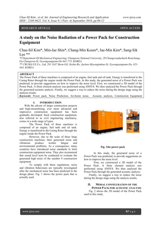
- 1. Chae-Sil Kim . et al. Int. Journal of Engineering Research and Application www.ijera.com ISSN : 2248-9622, Vol. 6, Issue 9, ( Part -4) September 2016, pp.08-12 www.ijera.com 8|P a g e A study on the Noise Radiation of a Power Pack for Construction Equipment Chae-Sil Kim*, Min-Jae Shin*, Chang-Min Keum*, Jae-Min Kim*, Sang-Sik Lee ** *(1 Department Of Mechanical Engineering, Changwon National University, 20 Changwondaehark-Rouichang- Gu Changwon-Si, Gyeongsangnam-Do 641-773, KOREA ** (2 BUMA CE Co., Ltd, 291 1637 Beon-Gil, Seobu-Ro, Juchon-Myeongimhae-Si, Gyeongsangnam-Do, 621- 843, KOREA ABSTRACT The Power Pack of these machines is composed of an engine, fuel tank and oil tank. Energy is transferred to the Casing Rotor through the engine inside the Power Pack. In this study, the generated noise of a Power Pack was predicted, to provide suggestions on how to improve the noise level. First, we constructed a 3D model of the Power Pack. A finite element analysis was performed using ANSYS. We then analysed the Power Pack through the generated acoustic analysis. Finally, we suggest a way to reduce the noise during the design stage using the analysis results. Keywords: Power pack, Noise Prediction, Air-borne noise, Acoustic analysis, Construction Equipment I. INTRODUCTION With the advent of larger construction projects and high-streamlining, ever more advanced and impressive construction equipment has been gradually developed. Such construction equipment, also referred to as civil engineering machinery, comes in a wide range of types. The Power Pack of these machines is composed of an engine, fuel tank and oil tank. Energy is transferred to the Casing Rotor through the engine inside the Power Pack. However, due to the scale of these large construction machines, their generated noise and vibrations produce worker fatigue and environmental problems. As a consequence, many countries have introduced noise standards to limit construction equipment noise. They also recommend that sound level tests be conducted to evaluate the generated high noise of the number 9 construction equipment. To comply with these regulations, noise and vibration behaviours are typically investigated after the mechanical noise has been predicted in the design phase. Fig. 1 shows the power pack that is actually used. Fig. 1the power pack In this study, the generated noise of a Power Pack was predicted, to provide suggestions on how to improve the noise level. First, we constructed a 3D model of the Power Pack. A finite element analysis was performed using ANSYS. We then analysed the Power Pack through the generated acoustic analysis. Finally, we suggest a way to reduce the noise during the design stage using the analysis results. II. MODAL CONFIGURATION OF THE POWER PACK FOR ACOUSTIC ANALYSIS Fig. 2 shows the 3D model of the Power Pack used in this study. RESEARCH ARTICLE OPEN ACCESS
- 2. Chae-Sil Kim . et al. Int. Journal of Engineering Research and Application www.ijera.com ISSN : 2248-9622, Vol. 6, Issue 9, ( Part -4) September 2016, pp.08-12 www.ijera.com 9|P a g e Fig. 2 the 3D model of the power pack As mentioned before, the Power Pack is composed of an engine, fuel tank and oil tank. The noise of the Power Pack can be divided into two types. When the engine is running inside the Power Pack, it produces mechanical noise. It also produces vibrations which affect the structure and generate mechanical noise. This secondary, radiated, noise is transferred to the air outside of the Power Pack during engine operation. In the first case, we considered the natural frequency and the detailed operating principles of the system. Then, we confirmed the presence of noise. In this study, analysis was performed by considering the second case, the noise induced by vibration, rather than an acoustic analysis of the engine mechanical noise. The following analysis conditions were set. First, we selected the acoustic analysis criteria based on the regulation of noise in KOREA. Second, we assumed that the main noise source was the engine noise of the Power Pack. Finally, we checked the effect on noise reduction by installing sound-absorbing materials in the Power Pack, using different sound-absorbing material thicknesses. 1.1. Slection of Power Pack criteria for Acoustic Analysis 1.1.1. Acoustic Analysis criteria depending of noise regulation KOREA has introduced noise regulations concerning construction equipment noise. Also, it recommends conducting sound level tests to evaluate the high generated noise of the number 9 construction equipment. To meet these restrictions, a noise level of a certain intensity or less is required. In this case, the Power Pack must comply with a limitation of no more than 110dB(A). Also, a sound level testing method was announced based on the Noise and Vibration law. In the case of a Power Pack, as seen in Fig. 3, microphones to measures the noise are installed at six receiving points. The microphone's positions in this study are the same as those shown in Table 1. Fig. 3 microphones to measure the noise at six points. Table 1The microphone positions Microphone no. X (m) Y (m) Z (m) 1 11.2 11.2 1.5 2 -11.2 11.2 1.5 3 -11.2 -11.2 1.5 4 11.2 -11.2 1.5 5 -4.32 10.4 11.36 6 4.32 -10.4 11.36 In order to conduct the acoustic analysis, it was first necessary to conduct a Power Pack Model and microphone position analysis, following the required noise test methods. The microphone position was analysed by the same methods. 1.1.2. Estimate of engine noise sources in Power Pack interior The main noise in the Power Pack interior is generated by the engine. As mentioned earlier, in this study we consider the noise transferred by air, excluding the machine noise of the engine. For this analysis, we have assumed that the engine is located at one point. In order to conduct an analysis of the radiated noise generated in the engine of the Power Pack interior, a noise source was adapted using a monopole source function of the acoustic analysis program. Fig. 4 is adapted to indicate the radiated noise of the engine. We calculated the radiated noise force as follows.
- 3. Chae-Sil Kim . et al. Int. Journal of Engineering Research and Application www.ijera.com ISSN : 2248-9622, Vol. 6, Issue 9, ( Part -4) September 2016, pp.08-12 www.ijera.com 10|P a g e Fig. 4 adapted to indicate the radiated (1) (2) (3) 1.1.3. Absorbing material selected for noise reduction of the Power Pack. In order to reduce engine noise, sound- absorbing material was attached to the sides of the Power Pack. The selected sound-absorbing material was NB Polyurethane Foam. Table 2 lists the properties of the sound absorbing material. Table 2 The properties of the sound absorbing material Density (kg/m3) Thickness (mm) Sound Absorption Coefficient (Hz) 125 250 500 70 25 0.09 0.20 0.41 50 0.17 0.45 0.81 Sound Absorption Coefficient (Hz) NRC 1000 2000 4000 5000 0.72 0.72 0.67 0.71 0.52 0.90 0.89 0.91 0.88 0.76 In this study, the acoustic analysis that was employed is unable to use separate sound frequency band coefficients. Therefore, to be used in the acoustic analysis, the sound absorbing properties of the material were changed to acoustic impedance. The following is the acoustic impedance equation. (4) (5) Then, Z1 and Z2 are the characteristic impedance equations. Table 3 shows acoustic impedance using the density and sound velocity of the medium. Table 3Acoustic impedance Air Polyurethane unit Density of medium p0 1.225 70 kg/m3 Sound velocity of sound in the medium c0 330 1900 m/s Impedance Z 404.25 133000 kg/m2·s As mentioned earlier, we selected the noise measurement, noise source and absorbing material in accordance with the regulations required for the noise acoustic analysis, then conducted the acoustic analysis of the Power Pack. 1.2. Building the FE Model and Acoustic Model of the Power Pack Fig. 5 presents the finite element method used in the 3D modelling, which was used to conduct the acoustic analysis of the Power Pack. We constructed three kinds of finite element models for noise reduction based on the type of installation of sound- absorbing materials. The basic model was constructed without a sound-absorbing material, and two models were prepared that applied sound absorbing materials, one with a thickness of 25mm and the other with a thickness of 50mm. The element type used was TETRA 4 of 4 node. The noise measurement range of the Power Pack refers to the noise measurement data inside the engine. We conducted the analysis using a noise component in the 20 Hz ~ 1,500 Hz range. The analysis used the FEM AML (Automatically Matched Layer) technique. It is also called FEMAO. When performing an acoustic analysis, it is not necessary to write directly to the PML layers. And also, if we create a PML layer, it reduces inconvenience, and the analysis time is shortened.
- 4. Chae-Sil Kim . et al. Int. Journal of Engineering Research and Application www.ijera.com ISSN : 2248-9622, Vol. 6, Issue 9, ( Part -4) September 2016, pp.08-12 www.ijera.com 11|P a g e Fig. 5 the finite element method used in the 3D modelling Fig. 6 shows the six microphone positions according to the Power Pack noise regulation. Also, the area outside of the Power Pack is designated as an AML area. After the Power Pack was assumed to be in the correct position on the ground, we conducted the acoustic analysis using the Symmetry Plane of Reflective ground conditions. Fig. 6 the six microphone positions III. RESULTS OF THE ACOUSTIC ANALYSIS OF THE POWER PACK As mentioned before, Fig. 7 ~ Fig. 8 provide the graphed results obtained using the acoustic analysis model of the Power Pack. Table 4 shows the analysis results of all six points. Table 4 is the average acoustic analysis at 20 Hz ~ 1,500 Hz and the results are for three conditions of sound- absorbing material installed at selected locations. In the acoustic analysis results, we investigated the occurrence of noise in the Power Pack depending on whether or not sound-absorbing material was used, and also checked whether there were small changes in noise depending on the thicknesses of the installed sound absorbing material. The derived analysis results found the Power Pack generated noise below the 110dB(A) limit of the Noise Regulations with or without the sound-absorbing material. Finally, we determined that the Power Pack met the requirements of the noise regulations without the use of sound-absorbing material. Fig. 7 the analysis results of Microphone- 1 Fig. 8 the analysis results of Microphone – 2 Table 4 The analysis results of all six points Base Base with Porous 25t Base with Porous 50t 1 80.51 71.73 69.57 2 81.05 72.57 72.29 3 85.17 79.43 79.55 4 84.7 76.39 77.12 5 82.85 75.22 74.15 6 81.82 73.40 72.02 Avg. 82.68 74.79 74.12 Unit :dB(A) IV. CONCLUSION In this study, in order to determine the level of noise generated by a large construction machine, and to investigate ways to improve the noise level, we performed an acoustic analysis of a model Power Pack. We selected six points outside the Power Pack for microphones to measure noise intensity, according to the standard noise and vibration regulation, then used this data to conduct the acoustic analysis using the FEM AML method. The Power Pack noise analysis results were as follows below. i. Using six points of noise measurement, the acoustic analysis of the Power Pack model without the absorbing material obtained an average noise level of 82.68 dB(A). The acoustic analysis of the model with 25mm thick with Polyurethane material sound-absorbing material attached to the Power Pack obtained an average noise level of 74.79 dB(A). The
- 5. Chae-Sil Kim . et al. Int. Journal of Engineering Research and Application www.ijera.com ISSN : 2248-9622, Vol. 6, Issue 9, ( Part -4) September 2016, pp.08-12 www.ijera.com 12|P a g e acoustic analysis of the model with the sound- absorbing material with a thickness of 50mm obtained an average level of 73.12 dB(A). Also, the three kinds of noise analysis models found that the noise and vibration that was generated was below the stated regulatory limit of 110 dB(A). Therefore, we believe this is a suitable model. ii. The result of the acoustic analysis using the three models for different sound-absorbing material found that the sound-absorbing material was better for noise reduction than the model with no sound-absorbing material attached, but, the changes in noise level due to the thickness of the sound-absorbing material were determined to be small. iii. In the results of the acoustic analysis graphs of the Power Pack, amplitudes in the high frequency range of 500Hz or more produced a high noise component. It was determined that this source was consistent with the emission characteristics of noise generated by the engine. In order to enhance the sound absorbing effect, high frequency absorption of low-frequency sound than is deemed necessary. iv. With reference to the selection of the six noise measurement points for the acoustic analysis, a physical model of the Power Pack should be built according to the noise and vibration regulation. At the same time, location as the noise measurement point must be carried out noise measurement test. By comparing the acoustic analysis results derived as a result of interpretation. This is deemed necessary to ensure the reliability of verification. v. In this study, the acoustic analysis techniques utilized the positioning and measurement of selected absorbing materials in the Power Pack. ACKNOWLEDGEMENTS This research was financially supported by the “Next-generation construction machinery component specialization complex development program” through the Ministry of Trade, Industry & Energy (MOTIE) and Korea Institute for Advancement of Technology (KIAT) and partly supported by the Vibration Durability Research Center (VIDEC) at Changwon National University. REFERENCES [1]. LMS Virtual. Lab REV13 Acoustic analysis [2]. C. S. Kim, C. M. Keum, J. M. Kim, D. I. Kim, S. S. Lee, Study on the effect of Noise for Internal Structure of Power Pack in Construction equipment, 2015 spring KSNVE Conf., 2015, 9-10 [3]. H. S. Lee, J. M. Oh, S. Y. Cho, S. J. Kim, I. D. Kim, Noise Radiation Prediction of Engine Using Multi-Body Dynamic Simulation, 2013 autumn KSNVE Conf., 2013, 623-624 [4]. J. H. Lee, J. H. Kang, K. K. Kang, H. T. Kwak, Exterior noise analysis of excavator using SEA, 2013 spring KSNVE Conf., 2013, 514-515 [5]. K. S. Oh, S. K. Lee, S. J. Kim, Prediction of the noise radiated by the structural vibration of a powertrain. 2007 spring KSNVE Conf., 2007, 861-866 [6]. T. Y. Kim, S. K. Lee, S. J. Kim, D. Y. Lee, Prediction of the radiated noise generated by fuel tank of LPG vehicle, 2016 autumn KSNVE Conf., 2006, 832-