IMPACT ANALYSIS ON ALUMINIUM AND MAGNESIUM 5 SPOKE ALLOY WHEEL USING FEA
F041036040
1. ISSN (e): 2250 – 3005 || Vol, 04 || Issue, 10 || October – 2014 ||
International Journal of Computational Engineering Research (IJCER)
www.ijceronline.com Open Access Journal Page 36
Design & Optimization of a Rim Using Finite Element Analysis 1,Turaka.venkateswara Rao , 2,Kandula. Deepthi , 3,K.N.D.Malleswara Rao 1 PG student, Department of Mechanical Engineering, Vikas College of Engineering & Technology, Nunna 2 Guide (Assit.Prof), Department of Mechanical Engineering, Vikas College of Engineering & Technology, Nunna 3Asst.prof, Department of Mechanical Engineering, P.C.C, Vijayawada, AP, INDIA
I. INTRODUCTION
The alloy used in the finest road wheels today is a blend of aluminum and other elements. The term "magnesium wheel" is sometimes incorrectly used to describe alloy wheels. Magnesium is generally considered to be an unsuitable alloy for road usage due to its brittle nature and susceptibility to corrosion. In market, mostly aluminum alloy wheel is used. Pure aluminum is soft, ductile, and corrosion resistant and has a high electrical conductivity. In consequence it is widely used for foil and conductor cables, but alloying with other elements is necessary to provide the higher strengths needed for other applications. Aluminum alloy wheels are cast into a mold in a hot liquid state and cooled, which makes them more accurate in both the heavier and lighter areas. The end result is a balance that has less weight on the wheel and less stress on the tire. Aluminum alloy wheels also provide a lighter weight for the racing enthusiast, and can be machined for a brilliant appearance. Steel wheels are a great way to provide basic transportation for a basic car, but for those who want to extend the life of their tires and have a smoother ride, alloy wheels are the way to go. Alloy metals provide superior strength and dramatic weight reductions over ferrous metals such as steel, and as such they represent the ideal material from which to create a high performance wheel. In fact, today it is hard to imagine a world class racing car or high performance road vehicle that doesn't utilize the benefits of alloy wheels.
II. MODELING BY USING PRO-E
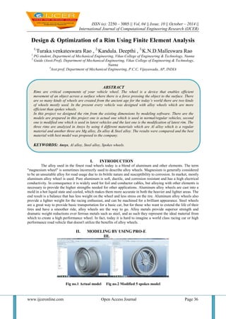
III. Fig no.1 Actual model Fig no.2 Modified 5 spokes model
ABSTRACT
Rims are critical components of your vehicle wheel. The wheel is a device that enables efficient movement of an object across a surface where there is a force pressing the object to the surface. There are so many kinds of wheels are created from the ancient age for the today’s world there are two kinds of wheels mostly used. In the present every vehicle was designed with alloy wheels which are more efficient than spokes wheels.
In this project we designed the rim from the existing dimensions by modeling software. There are the models are prepared in this project one is actual one which is used in normal/regular vehicles, second one is modified one which is used in latest vehicles and the last one is the modification of latest rim. The three rims are analyzed in Ansys by using 4 different materials which are Al alloy which is a regular material and another three are Mg alloy, Zn alloy & Steel alloy. The results were compared and the best material with best model was proposed to the company.
KEYWORDS: Ansys, Al alloy, Steel alloy, Spokes wheels.
2. Design & Optimization Of A Rim Using…
www.ijceronline.com Open Access Journal Page 37
Fig no.3 Optimized 4 spokes model III. RESULTS & DISCUSSION Actual rim model results: Al alloy: Fig no.4 Stress Fig no.5 Displacement 3.1.2 Steel alloy: Fig no.6 Stress Fig no.7 Displacement 3.1.3 Mg alloy: Fig no.8 Stress Fig no.9 Displacement 3.1.4 Zn alloy: Fig no.10 Stress Fig no.11 Displacement
3. Design & Optimization Of A Rim Using…
www.ijceronline.com Open Access Journal Page 38
3.2 Modified 5 spokes model results: 3.2.1 Al alloy: Fig no.12 Stress Fig no.13 Displacement
3.2.2 Steel alloy:
Fig no.14 Stress Fig no.15 Displacement 3.2.3 Mg alloy: Fig no.16 Stress Fig no.17 Displacement 3.2.4 Zn alloy:
Fig no.18 Stress Fig no.19 Displacement 3.3 Optimized 4 spokes model results: 3.3.1 Al alloy:
4. Design & Optimization Of A Rim Using…
www.ijceronline.com Open Access Journal Page 39
Fig no.20 Stress Fig no.21 Displacement 3.3.2 Steel alloy: Fig no.22 Stress Fig no.23 Displacement 3.3.3Mg alloy: Fig no.24 Stress Fig no.25 Displacement 3.3.4 Zn alloy: Fig no.26 Stress Fig no.27 Displacement
IV. RESULTS SUMMARY
Model
Material used
Al alloy
Steel alloy
Mg Alloy
Zn alloy
Actual model
Stress
46.5326
139.7056
31.929
56.931
Displacement
0.208
0.1363
0.2613
0.1932
Modified 5 spokes model
Stress
45.386
133.267
29.374
59.654
Displacement
0.231
0.1269
0.2938
0.1892
optimized 4 spokes model
Stress
39.486
126.254
34.894
54.326
Displacement
0.197
0.2012
0.2943
0.1802
Table no.1 results
5. Design & Optimization Of A Rim Using…
www.ijceronline.com Open Access Journal Page 40
V. CONCLUSION
The modeling is done in pro-e and the model was saved in the IGES format and imported into Ansys. In the ansys software the analysis of 3 models done by changing the materials. The results were tabulated and compared in the investigation we came to know that For actual rim the stress values are low for Mg alloy compared to all other alloys which are used in this project. The al Alloy and Zn alloy values are nearer to the Mg alloy so these alloys may use in the shortage of Mg alloy. For the modified 5 spokes model stress values are low for Mg alloy compared to other alloys and the results are nearly same for Al & Zn alloy and the situation is continues as actual rim model. In the optimized 4 spokes model also Mg alloy performs very good compared to all other alloy here also the situation is same. Form this we conclude that steel alloy not to recommend for any type of rims manufacturing and the Mg alloy is good for all types of rims manufacturing in the second place Al alloy may be used. In the consideration of models the new optimized 4 spokes can be used by changing the ribs thickness form this rims weight also reduces.
[1] Future scope: Further we can do optimization of material thickness to reduce the material consumption.
[2] Further we can improve life of component by using advanced fatigue strain life approach.
REFERENCES:
[1] google.com
[2] youtube.com
[3] ntpl
[4] machine design by RS KURMI
[5] SAE J175 Reaffirmed SEP2003
[6] www.nafems.com
[7] HyperWorks help, topology optimization
[8] K.J. Bathe, “Finite Element Procedures in Engineering Analysis”, Prentice-Hall, Inc.
[9] Design Guide and Procedures, Hyundai Motor Corporation.
[10] Nitin S. Gokhale, “Practical Finite Element Analysis”, Finite To Infinite
[11] K. Mahadevan and Balaveera Reddy, “Design Data Hand Book”.
[12] “Finite Element Analysis”, Chandra Pautla.
[13] “Strength Of Materials”, Ramambrutham.
[14] “Ansys User Manual”,
[15] “Metal Fatigue” , Ralfh Stefunson, Ali Fatemi & A.O. Cuph.
[16] “MSC Fatigue User Manual”,
[17] Metal_fatigue_in_engineering by Stefan.
[18] Fatigue Life Analysis of Aluminum Wheels by Simulation of Rotary Fatigue Test Liangmo Wang* - Yufa Chen - Chenzhi Wang - Qingzheng Wang School of Mechanical Engineering, Nanjing University of Science & Technology, China
[19] Fatigue properties of a cast aluminium alloy for rims of car wheels. .Bosi,G.L.Garagnani
[20] Modeling and Fatigue Analysis of Automotive Wheel Rim by subbarao