
Recommended
Recommended
More Related Content
What's hot
What's hot (19)
Similar to Ceramic Encased Wire Wound Power Resistors 10-40W
Similar to Ceramic Encased Wire Wound Power Resistors 10-40W (20)
Recently uploaded
Recently uploaded (20)
Ceramic Encased Wire Wound Power Resistors 10-40W
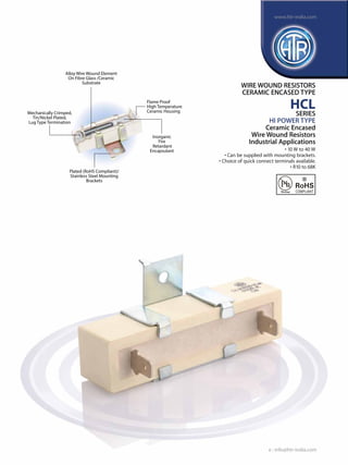
- 1. Alloy Wire Wound Element On Fibre Glass /Ceramic Substrate Flame Proof High Temperature Ceramic Housing Inorganic Fire Retardant Encapsulant Plated (RoHS Compliant)/ Stainless Steel Mounting Brackets Mechanically Crimped, Tin/Nickel Plated, Lug Type Termination WIRE WOUND RESISTORS CERAMIC ENCASED TYPE HCL SERIES HI POWER TYPE Ceramic Encased Wire Wound Resistors Industrial Applications • 10 W to 40 W • Can be supplied with mounting brackets. • Choice of quick connect terminals available. • R10 to 68K e : info@htr-india.com www.htr-india.com Rev Date : 22/11/2016 Asper AEC-Q200
- 2. HTR TYPE POWER RATING at 70°C L ±1.5 W ±1 P ±1.5 DIMENSIONS (mm) RESISTANCE RANGE TYPICAL WEIGHT PER PCFITTED WITH BRCT. (gms) CL-10 10W 48.0 9.5 9.5 35.0 (No Mounting Bracket) R10 47K 11.0 - CL-15 15W 48.0 12.5 12.5 35.0 14.0 12.0 3.0 R10 47K 18.5 24.5 CL-20 20W 63.5 12.5 12.5 48.0 14.0 12.0 3.0 R10 56K 22.0 28.0 CL-30 30W 76.0 (±2.0) 19.0 19.0 56.0 16.5 18.0 3.0 R20 64K 65.0 79.0 CL-40 40W 90.0 (±2.0) 19.0 19.0 71.0 16.5 18.0 3.0 1R0 68K 72.0 86.0 TYPICAL WEIGHT PER PC (gms) min max H ±1 S1 ±1 S2 ±0.5 S3 ±0.5 PHYSICAL CONFIGURATION WIRE WOUND RESISTORS CERAMIC ENCASED TYPE HCL ELECTRICAL CHARACTERISTICS / DATA PARAMETER/PERFORMANCE TEST & TEST METHOD PERFORMANCE REQUIREMENTS Power Rating (Rated Ambient Temperature) Full Power dissipation at 70°C and linearly derated to zero at 350°C (Refer Derating curve above) Operating Temperature Range (Ambient) -55°C to +350°C with suitable derating as per derating curve shown Voltage Rating / Limiting Voltage / V = PxR Max Working Voltage Maximum Overload Voltage Varies depending on resistance value, duration of overload and type of pulse waveform. (contact factory for details) Resistance Tolerances Available (JIS- C - 5202 para 5.1) ±10% (K); ±5% (J) e : info@htr-india.com www.htr-india.com Rev Date : 22/11/2016
- 3. ELECTRICAL AND ENVIRONMENTAL CHARACTERISTICS / DATA WIRE WOUND RESISTORS CERAMIC ENCASED TYPE HCL PARAMETER/ PERFORMANCE TEST TEST METHOD- DETAILS PERFORMANCE REQUIREMENTS Short Time Overload JIS-C-5202 Para 5.5 Condition B (voltage ∆R ± [2% + R05] corresponding to 10times power for 5 secs) Dielectric Withstanding JIS - C - 5202 Para 5.7 ∆R ± [1% + R05] Voltage / Voltage Proof Condition F (Limiting Voltage x 2 or 500V) Temperature Co-efficient of JIS - C - 5202 Para 5.2 ± 90 ppm/°C [>10R] Resistance ± 80 ppm/°C [<10R] ± 200 ppm/°C [<R10] Insulation Resistance JIS - C - 5202 Para 5.6 (condition F) >1000MΩ (min) Pulse Overload / JIS - C - 5202 Para 5.8 ∆R ± [2% + R05] Intermittent Overload (Limiting Voltage x 4) 1 sec on / 25 secs off 10,000 cycles ± 200 cycles Endurance - under load with JIS - C - 5202 Para 7.9 ∆R ± [5% + R05] - Typical humidity 1000 hours at 40°C ±2°C, 95% R.H with limiting voltage(1.5hours on / 0.5 hours off) Load Life JIS - C - 5202 Para 7.10 ∆R ± [3.5%+R05] - Average 1000 hours at 70°C with limiting voltage (1.5 hours on/0.5 hours off) Temperature Cycling JIS - C - 5202 Para 7.4 ∆R ± [2% + R05] - Typical [Room Temperature -55°C Room Temperature 155°C Room Temperature for 5 cycles] Damp Heat (Steady State) JIS - C - 5202 Para 7.5 ∆R ± [3% + R05] - Average Solvent Resistance JIS - C - 5202 Para 6.9 No effect on case filling or Solvent A - IPA for 60 secs ±10 secs marking Series HTR type Choice of Mounting LUG RoHS Compliance Resistance Value Tolerance HCL CL-20 B 6.2 * 15R J ORDERING INFORMATION 1. For RoHS version - CL-20 * 2. For Choice of Mounting i) If no bracket is required, to be left blank. ii) If M.S. bracket required - CL-20 B iii) If S.S. bracket is required - CL-20 BS 3. The Mounting Bracket‘B’will be zinc plated mild steel with trivalent passivaton to meet RoHS norms. The Mounting Bracket‘BS’will be stainless steel. 4. i) If lug required is compatible with Amp F187 - CL20 4.7 ii) If lug required is compatible with Amp 250 - CL20 6.2 5. CL20 type with Bracket‘B’, compatible with Amp 250 and RoHS compliant would be - CL20B 6.2 * MECHANICAL SPECIFICATIONS Pull Test / Robustness of Direct Load for 15 secs 2 to 4.5 kgs No effect Terminations depending on size Solderability JIS - C - 5202 Para 6.5 (Applicable to tin ∆R ± [1% + R05] plated terminations only) Dwell time in Continuous and satisfactory solder 2 secs ± 0.5 sec (95% Min coverage) TYPICAL APPLICATIONS HCL Series has been developed in the Far East as a direct replacement for old style radial wire wound resistors. As they can be provided with fitted mounting brackets, they are suitable for use in situations where shock and high frequency vibration forces are to be encountered. HCL Series also offers the following advantages - a) High degree of insulation b) Low surface temperature as the bracket itself acts to some extent as a heat sink. These resistors can also be supplied with a choice of receptacle type quick connect terminals which are compatible with AMP connector F187 and 250. Please refer ordering information. Note :The ceramic cases used may be steatite ceramic, corderite ceramic or high alumina ceramic.Thus, the ceramic cases may be off-white or variations of brown / grey, colours which are inherent to these ceramic material. PARAMETER/ PERFORMANCE TEST TEST METHOD- DETAILS PERFORMANCE REQUIREMENTS e : info@htr-india.com www.htr-india.com Rev Date : 22/11/2016