
Recommended
Recommended
More Related Content
What's hot
What's hot (20)
Similar to RL - CURRENT SENSE / LOW OHM CERAMIC ENCASED TYPE
Similar to RL - CURRENT SENSE / LOW OHM CERAMIC ENCASED TYPE (20)
Recently uploaded
Recently uploaded (20)
RL - CURRENT SENSE / LOW OHM CERAMIC ENCASED TYPE
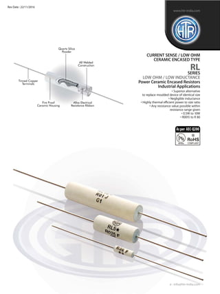
- 1. Quartz Silica Powder Fire Proof Ceramic Housing Alloy Electrical Resistance Ribbon All Welded Construction Tinned Copper Terminals CURRENT SENSE / LOW OHM CERAMIC ENCASED TYPE RL SERIES LOW OHM / LOW INDUCTANCE Power Ceramic Encased Resistors Industrial Applications • Superior alternative to replace moulded device of identical size • Negligible inductance • Highly thermal efficient power to size ratio • Any resistance value possible within resistance range given • 0.5W to 10W • R0015 to R 80 e : info@htr-india.com www.htr-india.com Rev Date : 22/11/2016 Asper AEC-Q200
- 2. HTR TYPE POWER RATING at 40°C (Ambient) L ±1 DIMENSIONS (mm) RESISTANCE RANGE RL0.5 0.5W 8 30 3 0.6/0.8 R004 R055 0.5 RL1 1W 10 30 3 0.6/0.8 R004 R10 0.6 RL2 2W 10 30 4 0.8/1.0 R002 R10 0.8 RL3 3W 14 40 5 0.8/1.0 R003 R22 1.1 RL4 4W 18 40 5 0.8/1.0 R003 R30 1.4 RL5 5W 22 45 8 1 R0015 R39 3.2 RL10 10W 42 60 9 1 R003 R80 6.5 TYPICAL WEIGHT PER PC (gms)min max LM ±1 d ±0.05 D ±1.0 • Resistance values must be checked using 4½ digit micro-ohm meter with four wire system and insulated clips. The resistance value must be checked at dimension LM as given in the table above. HTR TYPE TEMPERATURE AT FULL POWER DISSIPATION / LIMITING VOLTAGE Actual Temperature on Resistor Body RL0.5 700 C 500 C RL1 850 C 600 C RL2 1250 C 750 C RL3 1300 C 750 C RL4 1300 C 750 C RL5 1420 C 780 C RL10 2200 C 950 C Actual Temperature on Resistor Termination (10 mm from resistor body) • As temperature rise varies between different resistance values, if this parameter is required in detail, please provide details to the factory whereupon a suitable graph for that particular resistance value shall be provided. (Ambient Temperature 32°C) 4mm reduced solderability in this area CURRENT SENSE / LOW OHM CERAMIC ENCASED TYPE RL PHYSICAL CONFIGURATION TEMPERATURE RISE TABLE e : info@htr-india.com www.htr-india.com Rev Date : 22/11/2016
- 3. PARAMETER/PERFORMANCE TEST & TEST METHOD PERFORMANCE REQUIREMENTS ELECTRICAL & ENVIRONMENTAL CHARACTERISTICS / DATA CURRENT SENSE / LOW OHM CERAMIC ENCASED TYPE RL Power Rating (Rated Ambient Temperature) Full Power dissipation at 40°C and linearly derated to zero at 275°C (Refer Derating Curve above) Resistance Tolerances Available ±10% (K); ±5% (J); ±3% (H); ±2% (G); ±1% (F); ±0.5% (D) Temperature Range -55°C to +275°C with suitable derating as per derating curve Voltage Rating / Limiting Voltage / Max. Working Voltage V= PxR Voltage Proof / Dielectric Withstanding Voltage ∆R ± [0.2% + R05] - No flashover or mechanical (based on 1000V rms for 60 secs) damage Insulation Resistance (MIL STD 202F - Test Method 302) >1000M (Min) Short Time Overload ∆R ± [0.5% + R0005] - Average (5 x Rated Power upto 3 watts and ∆R ± [1% + R0005] - For resistance values near maximum range 10 x Rated Power 5 watts and above for 5 secs) Temperature Co-efficient of Resistance ± 60 to 400ppm/°C (Measured from -55°C to +125°C referenced to +25°C ) (Depending on resistance value) Thermal Shock (-65°C to +125°C, 5 cycles, ∆R ± [0.2% + R0005] - Average 15 mins at each extreme temperature) Mechanical Shock (Specified Pulse) ∆R ± [0.1% + R0005] - Typical (MIL STD 202F - Test Method 213B condition 'C') Moisture Resistance ∆R ± [0.2% + R0005] (MIL STD 202F - Test Method 106E with step 7b eliminated) Damp Heat (Steady State) / Humidity (40°C at 95% R.H for 250 hours) ∆R ± [0.5% + R0005] Endurance - Load Life ∆R ± [1.5% +R0005] Average-2000 hours duration (70°C with limiting voltage - 1.5 hours on / 0.5 hours off) ∆R ± [0.5% + R0005] Typical-1000 hours duration Solvent Resistance (IPA for 60 secs ± 10 secs) No effect on case filling / Marking MECHANICAL SPECIFICATIONS Pull Test / Robustness of Terminations No effect (Direct load 2 to 4.5 kgs depending on size for 15 secs) Resistance to Soldering Heat (260°C - 270°C for 4 secs) ∆R ± [0.1% + R0005] – Typical Solderability Must meet the requirements laid down (95% (MIL STD 202F – Test Method 208F) satisfactory coverage) Marking As per IEC Pub. 60062 PARAMETER/PERFORMANCE TEST & TEST METHOD PERFORMANCE REQUIREMENTS TYPICAL APPLICATIONS • RL series is an innovative method of providing low inductance resistors in a cylindrical ceramic body and is increasingly replacing the moulded version due to its performance superiority and lighter weight. • The resistive element consists of a flat metal band which is spot welded to the copper terminals before encapsulation. • Theresistors are findingincreasingusein industrialapplicationswhere pulseratingandability to absorbhighinrush currentis required. • Another important application is Current Sensing in applications which include switching and linear power supplies, instruments and power amplifiers. • For the effective utilization of these resistors, please refer to“Application/design notes for current sense resistors”. Note : Type RL 0.5 and RL - 1 can be supplied with lead diameter of 0.6mm instead of 0.8mm and RL2 / 3 & 4 can be supplied with lead φ of 1 mm instead of 0.8 mm. Please specify at the time of placing the order. Taping : Types RL 0.5, 1, 2, 3, 4, 5 and 10 can be supplied in taped form. Please refer to tape / ammo pack specifications. Note : The ceramic cases used may be steatite ceramic, corderite ceramic or high alumina ceramic. Thus, the ceramic cases may be off- white or variations of brown / grey, colours which are inherent to these ceramic material. 1. For RoHS version – RL2 * 2. For Tape / Reel packing – RL2 TR 3. For Tape / Ammo packing – RL2 T 4. If the current required during normal operation exceeds 31 amps on a continuous basis, it is advisable to opt for 2mm terminations. For this – RL4 (2), RL5 (2), RL10 (2) 5. Specify lead diameter at the time of ordering. RL1 (6) OR RL3 (1) ORDERING INFORMATION Series Type Packing Resistance Value Tolerance Bulk RL5 / RL5* RL RL5 / RL5* Tape Ammo RL5T/RL5*T R005 J Tape Reel RL5TR/RL5*TR e : info@htr-india.com www.htr-india.com Rev Date : 22/11/2016