
Recommended
More Related Content
What's hot
What's hot (20)
Similar to Hammond d v dt load filter
Similar to Hammond d v dt load filter (20)
Recently uploaded
Recently uploaded (20)
Hammond d v dt load filter
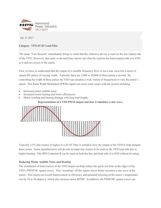
- 1. Jul. 31 2017 Category: VFD dV/dT Load Filter The name “Line Reactor” immediately brings to mind that this inductive device is used on the line (input) side of the VFD. However, that same or de-rated line reactor can often be used on the load (output) side of a VFD as it delivers power to the motor. First, we have to understand that the output of a variable frequency drive is not a sine wave but a series of square DC pulses of varying width. Typically there are 2,000 to 20,000 of these pulses a second. By controlling the width of these pulses the VFD can simulate a wide variety of frequencies to vary the motor’s speed. This Pulse Width Modulated (PWM) signal can cause some issues with the system including: Increased motor audible noise Increased motor heating and lower efficiencies Motor winding and bearing damage with long lead lengths Representation of a VFD PWM output and how it simulates a sine wave. Typically a 5% line reactor or higher or a dV/dT filter is installed close the output of the VFD to help mitigate these issues. Some manufacturers will de-rate an input line reactor to be used on the VFD load side due to higher heating. The HPS Centurion R can be used on both the line and load side of a VFD without de-rating. Reducing Motor Audible Noise and Heating The installation of load reactors at the VFD output can help reduce the quick rise time at the edges of the VFD’s PWM DC square waves. This “rounding” off the square waves better recreates a sine wave at the motor. This causes an overall improvement in efficiency and potential lowering of the motor’s temperature rise by 10 to 20 degree C which also increase motor MTBF. In addition, the PWM DC square waves can
- 2. cause a higher pitched audible whine in a motor. Adding an output line reactor can reduce the audible motor noise by 3 dB or more. Motor Winding and Bearing Damage with long lead lengths. Drive manufactures will typically designate a wire length between the VFD and motor that if exceeded, a reflected wave phenomenon may occur. In this instance, the output voltage of the drive can be multiplied by either two or four times the base voltage. This typically occurs somewhere in the motor windings or cable run. If this occurs it typically manifests itself as: Over-Voltage Cable Failures Motor Winding Insulation Failure Bearing failure: o The high voltage charge escapes the winding’s insulation but does not cause immediate insulation failure. One of the most likely paths to ground for the charge is through the windings, across the bearings and through the motor shaft to the grounded machinery. The arcing through the lubricant on the motor bearings causes tiny pits to form. If enough pits form, bearing failure will occur. While a line reactor may also help mitigate the issue, a dV/dT filter will better lower the top voltage of the reflected wave, especially at longer lead lengths. If using a line reactor, a minimum of 5% is recommended, higher impedances can be achieved by wiring 2 reactors in series. Typically adding a dV/dT filter to the output of a VFD will increase the rise time of the edge of the DC pulses and mitigate issues with reflected waves. A dV/dT filter combines a line reactor with an RC filter board that acts as a snubber circuit. If the VFD to motor distances exceeds 1000’, other technologies such as sine wave filters may need to be considered.