More Related Content Similar to 860651 Dok En (20) 2. Integration Instructions Laser Sources with NLS
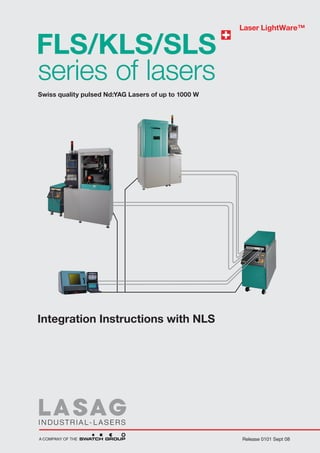
Integration Instructions Laser Sources with NLS
The Installation Instructions presented here serve the authorized personnel as a instruction- and working
tool for the electrical integration of the laser sources into a processing installation with NLS and for the
setting up of such an installation to suit the laser.
The Integration Instructions are part of the three volume user documentation.
DANGER
! For your own safety
Before you carry out any work on or - with the LASAG laser sources, you must
absolutely read the chapter of the Safety Information in the Operater Instructions as
well as the chapters corresponding to the respective activities.
Product Identification
These Integration Instructions are applicable to the following laser sources:
KLS 246 all types
SLS 200 all types
FLS all types
SLAB N
NA N all types
These integration instructions are updated for the laser control NLS V80.
Switzerland
LASAG AG • C.F.L. Lohnerstrasse 24 • CH-3602 Thun • Switzerland
Phone +41-33-227 4545 • Fax +41-33-227 4573 • lasers@lasag.ch • www.lasag.com
USA
LASAG Industrial-Lasers • A Division of the SWATCH Group (US) Inc.
1615 Barclay Boulevard • Buffalo Grove, IL 60089 • U.S.A.
Phone +1-847-483 6300 • Fax +1-847-483 6333 • lasers@lasag.com
Germany
LASAG Industrial-Lasers • A Division of the SWATCH Group (Deutschland) GmbH
Hohenzollernstrasse 16 • D-75177 Pforzheim • Germany
Phone +49-7231-3872 670 • Fax +49-7231-3872 679 • lasag-d@swatchgroup.com
Italy
LASAG Industrial-Lasers • A Division of LASCOR S.p.A.
Via Piave 98 • IT-21018 Sesto Calende • Italy
Phone +39-0331-924 881 • Fax +39-0331-919 384 • lascor@swatchgroup.com
Japan
LASAG Industrial-Lasers • A Division of the SWATCH Group (Japan) KK
Nippon Express BILT-1, 5F • Baraki, 2526-23, Ichikawa-shi, Chiba, 272-0004 • Japan
Phone +81-47-329 7099 • Fax +81-47-328 3590 • lasag@jp.swatchgroup.com
INDUSTRIAL - LASERS
Lasag AG, Thun, 10.01.08 CM 86 . 0651 - 00 - 01
A COMPANY OF THE
3. Integration Instructions Laser Sources with NLS
Table of contents
Chapter 1 Introduction and additional Safety Notices 86.0651-01
Chapter 2 Laser Materials Processing 86.0651-02
Chapter 3 Start-up and further Life cycles 86.0651-03
Chapter 4 Setting-up a Processing Installation 86.0651-04
Chapter 5 System Interfaces 86.0651-05
Chapter 6 USER Interfaces X51 and X52 86.0651-06
Chapter 7 Setting-up and Settings of the Laser Control System 86.0651-07
Chapter 8 Terminals and Modem Operation 86.0651-08
Chapter 9 Schematic Diagrams Mains Connection and User Interfaces 86.0651-09
Chapter 10 Schematic Diagrams Accessories and Terminals 86.0651-10
INDUSTRIAL - LASERS
Lasag AG, Thun, 10.01.08 CM 86 . 0651 - 00 - 02
A COMPANY OF THE
4. Integration instructions
Laser sources with NLS
1 Introduction and additional
safety notices
1 Introduction and additional safety notices
Table of contents
1.1 Foreword 2
1.1.1 Documentation overview 2
1.1.2 Exemption from liability 2
1.1.3 Copyright 2
1.2 Authorised persons 3
1.2.1 Personnel qualification for setting up a processing unit 3
1.2.2 Personnel qualification for the integration procedure 3
1.2.3 Personnel qualification for making the connection to the mains 3
1.2.4 Personnel qualification for individual chapters 3
1.2.5 Training 3
1.3 Additional safety notices 3
1.4 Danger signs and labels for processing systems and processing dangers 4
1.5 Statutory regulations governing integration work 4
1.6 Brief instruction on the integration of LASAG lasers 5
1.6.1 Overview 5
1.6.2 Space requirement 6
1.6.3 Heat dissipation 7
1.6.4 Mains power connection 9
1.6.5 Process gases and extraction 10
1.6.6 Personal safety 10
1.6.7 Drive 12
1.6.8 Operation 15
1.6.9 Customer services 16
INDUSTRIAL- LASERS © Lasag AG, Thun, 10.01.08 CM 86 . 0651 - 01 - 0
A COMPANY OF THE
5. Integration instructions
Laser sources with NLS
1 Introduction and additional
safety notices
1.1 Foreword
1.1.1 Documentation overview
The user documentation consists of the following three volumes:
Operator instructions
The operator instructions are to be used by the user staff as a training and working aid for the safe and
appropriate operation and maintenance of LASAG laser sources.
Integration instructions
The integration instructions are to be used by the integration staff as a training and working aid for
- creating the customer-based installations for commissioning the laser source
- the electrical integration of the laser sources with NLS into a processing unit
- the laser-based installation of a processing unit
- the safe handling of the laser source in the other life-cycle phases
Service instructions
The service instructions describe to the service personnel the safe implementation of the commissioning
procedure and maintenance plan, the safe repair if faults should occur, and gives details of spare parts.
Customer-specific documents and updates relating to all instructions are contained in chapter 9 of the
Operator instructions.
1.1.2 Exemption from liability
LASAG AG is not liable for any faults in this documentation. Liability for direct and indirect damage arising
from the delivery or use of this documentation is excluded provided this is legally permissible.
1.1.3 Copyright
Reprinting this document, including extracts of it, is prohibited. No part of this document may be re-
produced in any form, or processed, duplicated or distributed by any means - electronic, mechanical,
photocopying, recording or otherwise - without the written permission of LASAG AG. All rights reserved,
especially the right of duplication and translation, and the patent or registration rights.
INDUSTRIAL- LASERS © Lasag AG, Thun, 10.01.08 CM 86 . 0651 - 01 - 0
A COMPANY OF THE
6. Integration instructions
Laser sources with NLS
1 Introduction and additional
safety notices
1.2 Authorised persons
1.2.1 Personnel qualification for setting up a processing unit
In terms of instructions and assessment, the setting up of a laser unit requires a person with experience
in this work who must have successfully completed a course for laser safety advisers recognised by the
authorities.
1.2.2 Personnel qualification for the integration procedure
These activities may be carried out only by professional technical staff of this discipline or by staff pos-
sessing the equivalent mechanical and electrical knowledge. The acceptance testing of the work relating
to safety functions and to compliance with the relevant standards must be done by a member of the
technical staff trained for this.
1.2.3 Personnel qualification for making the connection to the mains
Personnel who make the mains connection require an authorization in accordance with state
regulations.
1.2.4 Personnel qualification for individual chapters
Additional personnel qualifications are also required for individual chapters.
1.2.5 Training
The manufacturer's customer service shall be pleased to provide information on training courses.
1.3 Additional safety notices
DANGER
Electric shock
During all work on parts of electrical systems, the mains supply is to be disconnected
from all terminals on the customer side and to be locked with a padlock. Parts of electrical
systems are to short-circuited with the grounding connector before they are touched.
DANGER
Reduced safety if cables are damaged
Lay cables for safety circuits and warning lamps in such a way as to protect them against
all types of damage. Warning lamps must be redundant (several of them) or fail-safe.
CAUTION
Risk of tripping with badly laid cables.
Lay cables away from walking and rest areas.
INDUSTRIAL- LASERS © Lasag AG, Thun, 10.01.08 CM 86 . 0651 - 01 - 0
A COMPANY OF THE
7. Integration instructions
Laser sources with NLS
1 Introduction and additional
safety notices
1.4 Danger signs and labels for processing systems and
processing dangers
Danger signs and labels for the processing systems will be installed by the integrator.
Danger signs and labels for the processing systems will be installed by the operator.
1.5 Statutory regulations governing integration work
Laser standard EN 60825-1:1994 applies in general, and it also contains important sections for the ope-
rators of laser equipment.
Installers and operators of laser processing systems are covered by ISO standards of class 11553: 1996
and EN 12626: 1997.
In addition, the state regulations must be complied with. For instance, in the USA the directive U.S. 21
CFR 1040.10 and 1040.11 (FDA) applies to laser equipment. ANSI Z 136.1: 1993 “For the safe use of la-
sers” applies in addition to operators.
INDUSTRIAL- LASERS © Lasag AG, Thun, 10.01.08 CM 86 . 0651 - 01 - 0
A COMPANY OF THE
8. Integration instructions
Laser sources with NLS
1 Introduction and additional
safety notices
1.6 Brief instruction on the integration of LASAG lasers
1.6.1 Overview
Introduction
Sales discussion Integration / Installation
of LASAG lasers
• Operator training (1 day)
• Service and maintenance (2 days)
Order
• Integration / Installation (1 day)
• Application training (1-2 days)
• Integration instructions
Order confirmation • Commissioning checklist
returned to LASAG completed
Installation On receipt of the completed checklist
über 1000 mm
Commissioning checklist
bis 2000 mm
± 0,5 mm
Abweichungen für Masse ohne Toleranzangaben
See chapter 3.1.8
• The IBN checklist ensures that the conditions for commissioning the laser
have been met by the desired time (power, water connections, etc.)
über 315 mm
bis 1000 mm
• 1 completed copy per commissioning location is returned to LASAG
± 0,3 mm
• The distribution is adapted to the circumstances on a case by case basis
1
über 120 mm
Checklist
bis 315 mm
± 0,2 mm
Endkunde
LASAG Final
Customer
über 30 mm
bis 120 mm
± 0,15 mm
2 Checklist
Example: the distribution if LASAG sells directly to the end customer
bis 30 mm
± 0,1 mm
ung dürfen sie nicht kopiert, vervielfältigt, auch niemals dritten Personen
errecht an diesen Zeichnungen und allen Beilagen, die dem Empfänger
anvertraut sind, verbleibt jederzeit unserer Firma. Ohne schriftliche
der zugänglich gemacht werden.
INDUSTRIAL- LASERS © Lasag AG, Thun, 10.01.08 CM 86 . 0651 - 01 - 0
A COMPANY OF THE
AG, Thun
9. Integration instructions
Laser sources with NLS
1 Introduction and additional
1 Aufbau und Dimensionen
1 Setup and Dimensions safety notices
Overall documentation Laserquelle FLS N/C/CL
Laser source FLS N/C/CL
Operator instructions
• Safety notices, 2410
layout and function, menus, operation, error messages, maintenance,
150 100 780
customer-specific documents
460 1950
Integration instructions
• Safety notices, laser material processing, commissioning, setup,
interfaces, laser control, terminals, schematic diagrams
2015*
1
Service instructions
1410*
• Safety notices, technical data, WRD, error messages, accessories, adjustments, repair,
1206*
2
maintenance, schematic diagrams
1 Aufbau und und Dimensionen
1 Aufbau Dimensionen
100*
3
1 Setup and and Dimensions
1 Setup Dimensions
1.6.2 Space requirement
*) mobile Option +25mm
Laserquelle FLS N/C/CL
Laserquelle FLS N/C/CL
FLS Laser
FLS 542N, 552N, 642N, 652N, 1042N/C/CL Laser source FLS N/C/CL
Laser source FLS N/C/CL
1760 150 100 780 2410 2410 150 150 100 100 780 780
Anschlüsse
460 1300 460 460 1950 1950
Netz
Steckerplatte
Kühlwasser
Connections
2015*
2015*
2015*
1
1 Mains 1 1
2 Connector plate
1410*
1410*
1410*
1206*
1206*
1206*
3 Cooling water
2 2
2
100*
100*
3 3
3
100*
*) mobile Option +25mm *) mobile*) mobile Option +25mm
Option +25mm
FLS 342N, 352N542CL
FLS FLS 542N, 552N, 642N, 652N, 1042N/C/CL
FLS 542N, 552N,FLS 1042CL1042N/C/CL
642N, 652N, Min. wall clearance:
FLS 342N 1760 1760 FLS 642N 150100
150 100 780 780 100 mm
Anschlüsse
Anschlüsse
FLS 352N 460 460 1300
FLS 652N
1300
Netz Netz
FLS 542N FLS 1042N Steckerplatte
Steckerplatte
FLS 552N Kühlwasser
Kühlwasser
INDUSTRIAL - LASERS
DS: 47-20-05, 90-10-20 Lasag AG, Thun, 18.09.06 CM 86 . 0392 - 01 - 01 Connections
Connections
2015*
2015*
1 1
1 Mains Mains
1
A COMPANY OF THE
2 Connector plate plate
2 Connector
1410*
1410*
1206*
1206*
3 Cooling water water
3 Cooling
2 2
3 3
100*
100*
*) mobile*) mobile Option +25mm
Option +25mm
FLS 342N, 352N352N
FLS 342N,
INDUSTRIAL- LASERS I N D U S T N DA L - R AA L - S A S E R S
I RI UST L I SERL © Lasag AG, Thun, 10.01.08 Thun, 18.09.06 86 . 0651 0392 .-039201 - 01
DS: 47-20-05, 90-10-20
DS: 47-20-05, 90-10-20 Lasag AG, Thun, 18.09.06 CM86 . - 86 010 01
Lasag AG,
CM CM 01 - - -
A COMPANY OF THE OF THE
A COMPANY
A COMPANY OF THE
10. 1 1Setup and Dimensions
Setup and Dimensions
Laserquelle KLS 246
Laserquelle KLS 246
Laser source KLS 246
Laser source KLS 246
Integration instructions
Laser sources with NLS
1 Introduction and additional
1 Setup and Dimensions
safety notices
1 Setup and Dimensions
Laserquelle SLS 200 CL/CL8
Laserquelle SLS 200 CL/CL8
Laser source SLS 200 CL/CL8
KLS and SLS lasers Laser source SLS 200 CL/CL8
KLS 246 SLS 200
KLS 246CL SLS 200 CL
I N D U S TS T A LA-L L-AL A S E R S
INDU RIRI SERS
DS: 47-20-07, 90-10-20
DS: 47-20-07, 90-10-20 Lasag AG, Thun, 13.03.98 FPFP
Lasag AG, Thun, 13.03.98 86860392 - 01010303
. . 0392 - - -
A COMPANY OFOF THE
A COMPANY THE
Provide access to service hatches:
• keep 0.8 m clear on both sides or
• unit can be moved
• SLS 200 CL16: Free circulation of air must be provided both from the side (inlet) and from below - 02 - 10
86 . 0444
INDUSTRIAL- LASERS DS: 47-20-11, 90-10-20 © Lasag AG, Thun, 29.09.06 CM
(outlet). 86 . 0444 - 02 - 10
INDUSTRIAL- LASERS
A COMPANY OF THE
DS: 47-20-11, 90-10-20 © Lasag AG, Thun, 29.09.06 CM
A COMPANY OF THE
1.6.3 Heat dissipation
See also chapter 3.1.5
• All laser power supplies are water-cooled, except those for the SLS 200 CL16 and the DLS.
They are air-cooled.
• An industrial or drinking water supply is required for the water cooling.
• The air-cooled devices give off their heat into the surroundings.
• The water-cooled devices also give off a little of their heat into the room.
• At temperatures below 3°C the lasers cannot be switched because of the risk of
frozen cooling water.
The following applies to all devices:
• Ambient temperature (operation) 10...35°C (average over 24 h) max. 40°C
• Ambient temperature (storage) 5...40°C
• Max. rel. humidity 80%
• Max. noise level 65 dBA, at a distance of 1 m (SLS 200 CL16: 70 dBA)
INDUSTRIAL- LASERS © Lasag AG, Thun, 10.01.08 CM 86 . 0651 - 01 - 0
A COMPANY OF THE
11. Integration instructions
Laser sources with NLS
1 Introduction and additional
safety notices
Heat dissipation into the room
Laser type Max. heat dissipation Max. air intake temperature
SLS 200 CL16 2.5 kW 40°C
Other lasers ≤ 0.4 kW + laser power 40°C
Water connection
The following applies to all water-cooled laser types:
Min. water pressure 4 bar
Max. water pressure 8 bar
Max. water temperature (inlet) 20°C
Min. water temperature (inlet) 10°C
Drinking or industrial water
Water quality
Non-corrosive for non-ferrous metals
Recommended hose size Nominal diameter (ND) 16 mm
Recommendation:
• Connect the supplied electrically operated water valve directly to the wall-mounted water connec-
tion in order to make a non-pressurised hose connection to the laser.
• If the drain line is also pressurised, then it too must be made into a non-pressurised connection by
means of a water valve.
The water consumption and heat discharge into the water can be found in the technical data in chapter 2
of the service instructions.
INDUSTRIAL- LASERS © Lasag AG, Thun, 10.01.08 CM 86 . 0651 - 01 - 0
A COMPANY OF THE
12. Integration instructions
Laser sources with NLS
1 Introduction and additional
safety notices
1.6.4 Mains power connection
See also chapter 3.1.6
• The fuse protection on the customer's premises must be in accordance with the table below.
• In order to comply, a safety cut-out switch with characteristic D curve (10..14xIn for max.
0.5..1.5 sec., in accordance with EN 60898) is recommended.
• In the event of failure of the safety cut-out all 3 phases must be disconnected from the mains simul-
taneously (all-phase switch-off)
• For optimum personal safety, the installation of a residual current circuit breaker with a sensitivity
of 300 mA is recommended on the customer's premises.
• The laser power supplies for the FLS series and the SLS 200 CL16 are suitable for connection to
50 Hz and 60 Hz mains power supplies.
• The laser power supplies of the KLS 246, SLS 200 and SLS 200CL series (except CL16) can be sup-
plied either for 50 Hz or 60 Hz mains power supplies.
Rated power, power consumption and fuse protection can be found in the technical data in Chapter 2 of
the service instructions.
INDUSTRIAL- LASERS © Lasag AG, Thun, 10.01.08 CM 86 . 0651 - 01 - 0
A COMPANY OF THE
13. Integration instructions
Laser sources with NLS
1 Introduction and additional
safety notices
1.6.5 Process gases and extraction
See also chapter 2
Process gases
Process gases are frequently used to achieve optimum processing.
Process Gases Pressure Consumption
Drilling O2, N2, Air 6-15 bar 50-100 l/min
Cutting O2, N2, Air 2-20 bar 20-150 l/min
Welding Ar, H2, He 1-4 bar 10-30 l/min
Extraction
• Some toxic by-products are produced by the working process
(vapours, smoke, ash, gases).
• It is recommended that a suitable extraction unit with appropriate filters (fine dust, active carbon) is
installed.
• In all cases the local regulations (maximum allowable concentrations, MAC list) must be complied
with.
1.6.6 Personal safety
über 1000 mm
bis 2000 mm
See also chapters 4 and 5
± 0,5 mm
Abweichungen für Masse ohne Toleranzangaben
Basic diagram showing the Emergency-off link between laser and processing machine.
über 315 mm
bis 1000 mm
± 0,3 mm
Maschine Laser
Machine
über 120 mm
bis 315 mm
± 0,2 mm
Not-Aus/E-Stop Not-Aus/E-Stop
über 30 mm
bis 120 mm
± 0,15 mm
Safety- Safety-
Relay Relay
bis 30 mm
± 0,1 mm
X50
sie nicht kopiert, vervielfältigt, auch niemals dritten Personen
diesen Zeichnungen und allen Beilagen, die dem Empfänger
sind, verbleibt jederzeit unserer Firma. Ohne schriftliche
INDUSTRIAL- LASERS © Lasag AG, Thun, 10.01.08 CM 86 . 0651 - 01 - 10
glich gemacht werden.
A COMPANY OF THE
14. Integration instructions
Laser sources with NLS
1 Introduction and additional
safety notices
Class 1 laser (default “normal case”):
Processing room enclosed
Operating hatch secured with interlock switch
Operators not exposed to any laser radiation
über 1000 mm
bis 2000 mm
± 0,5 mm
Abweichungen für Masse ohne Toleranzangaben
Bedienungsöffnung mit Interlaockschalter
Operation door with Interlock-switch
über 315 mm
bis 1000 mm
± 0,3 mm
über 120 mm
über 1000 mm
bis 315 mm
bis 2000 mm
± 0,2 mm
± 0,5 mm
Abweichungen für Masse ohne Toleranzangaben
Bedienungsöffnung mit Interlaockschalter
Operation door with Interlock-switch
über 315 mm
bis 1000 mm
über 30 mm
bis 120 mm
± 0,15 mm
± 0,3 mm
Y
X
über 120 mm
bis 30 mm
bis 315 mm
± 0,1 mm
± 0,2 mm
Bearbeitungsraum laserdicht
Working room laserproof
über 30 mm
bis 120 mm
± 0,15 mm
Y
Genehmigung dürfen sie nicht kopiert, vervielfältigt, auch niemals dritten Personen
Das Urheberrecht an diesen Zeichnungen und allen Beilagen, die dem Empfänger
X
Class 4 laser (allowed only as an exception):
persönlich anvertraut sind, verbleibt jederzeit unserer Firma. Ohne schriftliche
Zugangstür mit Interlockschalter
bis 30 mm
± 0,1 mm
Entrance door with Interlock-switch
work room secured against unauthorized access with interlock switch
Bearbeitungsraum laserdicht
Operators can be exposed to direct laser radiation or unwanted radiation and must wear protective
Working room laserproof
clothing.
Genehmigung dürfen sie nicht kopiert, vervielfältigt, auch niemals dritten Personen
Das Urheberrecht an diesen Zeichnungen und allen Beilagen, die dem Empfänger
mitgeteilt oder zugänglich gemacht werden.
persönlich anvertraut sind, verbleibt jederzeit unserer Firma. Ohne schriftliche
Zugangstür mit Interlockschalter
Entrance door with Interlock-switch
© LASAG AG, Thun
Y
X
mitgeteilt oder zugänglich gemacht werden.
Raum laserdicht, Bedienpersonal mit Schutzkleidung
wird verwendet für Room laserproof, operating personnel with protection clothes
to the recipient personally, remain vested in our company at all times. The same may not be
The Copyright for all of the drawings and related appendages, wich have been handed over
© LASAG AG, Thun
86.0650 01 11.indd
Y
Furthermore, they may not be made available or otherwise disclosed to any third party.
copied or replicated in any way in whole or in part without our prior consent in writing.
X
Datei Typ: ai
Werkstoff Therm. Behandlung Oberfläche Bearbeitung
Raum laserdicht, Bedienpersonal mit Schutzkleidung
wird verwendet für Room laserproof, operating personnel with protection clothes
to the recipient personally, remain vested in our company at all times. The same may not be
The Copyright for all of the drawings and related appendages, wich have been handed over
Änderungen Ersetzt durch Kanten ohne Angaben
86.0650a01 11.indd
00.00.07 CM b c d 0,2-0,3 mm brechen
Furthermore, they may not be made available or otherwise disclosed to any third party.
copied or replicated in any way in whole or in part without our prior consent in writing.
Ersatz für
e f g h Gewinde 6H/6g
Masstab Gezeichnet
01.10.07 CM
Datei Typ: ai
Integrationsanleitung Kapitel 1 Pictures Geprüft
Therm. Behandlung
1:1
Werkstoff Oberfläche BearbeitungFreigegeben
© LASAG LTD, Thun
DS 00-00-00
Änderungen Ersetzt durch Kanten ohne Angaben Dok
Artikelnummer Blatt
b c
86.0650 01 03
a 00.00.07 CM d 0,2-0,3 mm brechen
INDUSTRIAL- LASERS Ersatz für
e f g h Gewinde 6H/6g
Masstab Gezeichnet
01.10.07 CM
Integrationsanleitung Kapitel 1 Pictures Geprüft
1:1
Freigegeben
© LASAG LTD, Thun
DS 00-00-00
Artikelnummer Dok Blatt
INDUSTRIAL- LASERS © Lasag AG, Thun, 10.01.08 CM 86 . 0651 - 01 - 11
INDUSTRIAL- LASERS 86.0650 01 03
A COMPANY OF THE
15. Integration instructions
Laser sources with NLS
1 Introduction and additional
safety notices
1.6.7 Drive
See chapter 6
Parallel interfaces USER1...8
• The laser can be remote-controlled via the USER interfaces using standard 24V interfaces.
• Ideal for controlling SPS control systems.
• The USER1 interface on plug X51 is fitted as standard to every laser.
• Other interfaces are optional.
• Some options require a 2-board NLS.
USER1, standard, 1-board NLS adequate
Signal description Designation
1 Action group request and acknowledge signal. RC, RCA
The action groups must not be occupied by a terminal
if the USER interfaces are to be used to control the system.
2 Laser clock signals RF, TP
switch over to external laser clock and input for external trigger pulse.
Stop signal to block laser pulses. HL
Stop signal to block laser pulses. FP, WP
3 Driving the beam shutter, SOC, SO
opens and closes the beam shutter with acknowledge signal.
4 Triggering a series of pulses PB
corresponds to the number of pulses contained in the WPS.
5 Ramping PR
triggers a continuous transition to the ramping pulse width
or goes back to the normal pulse width.
6 Gas valve GVALV
opens and closes the gas valve in the processing head.
7 Choosing recipes 1 – 3 LP0, LP1
choice of other recipes with USER 3B.
8 Selection of fiber optic cable statuses 0 - 3 LL0, LL1, FINP1
provided a corresponding time sharing configuration was selected for the
fiber-optic cables. Choice of other fiber-optic cable statuses with USER 3B.
Acknowledge signal that the status has been achieved.
9 Output to indicate laser status. OK
The signal can be configured with an integrator parameter in accordance with
requirements.
USER 2A, optional, 2-board NLS required
• USER2 is the parallel interface for CNC or SPS for transmitting laser parameters to the laser
control system and also for the WPS and all recipes.
• The ST and TSS protocols are supported.
INDUSTRIAL- LASERS © Lasag AG, Thun, 10.01.08 CM 86 . 0651 - 01 - 12
A COMPANY OF THE
16. Integration instructions
Laser sources with NLS
1 Introduction and additional
safety notices
USER 3B, optional, 2-board NLS required
Signal description Designation
1 Choice of recipes 4 - 15, in addition to recipes 1 - 3 LP2, LP3
that can even be selected with signals on USER1.
2 Selection of the fiber-optic cable statuses 5 - 8 in addition to LL2
fiber-optic cable statuses 1 – 4,
that can even be selected with signals on USER1.
3 Input for switching off the laser. LOFF
In the event of external error conditions, e.g. in the CNC, the laser can be
switched off.
4 Output to indicate laser status. LSTAT0
This output is in addition to the OK output and can also be configured to be
the same.
USER 4A, optional, no 2-board NLS required, combination with USER 3B required.
• The two interfaces USER 3B and USER 4A give improved integration of the laser into a higher-order
machine.
• They allow the laser to be powered up or down via the SPS, without having to execute manual func-
tions or checks on the laser.
• The interlock key switch has a third position to allow it to switch over to local function if maintenance
work is required.
• In addition, there is also a message contact at the mushroom-shaped emergency-off button.
USER 5A, optional, 2-board NLS required
• This option provides a second opener contact at the mushroom-shaped emergency-off button.
(For those users who do not need the other functions of USER 4A).
USER 6A, multiple workstations, optional, 2-board NLS not required
• This interface provides the interlock and fiber-shutter signals that are needed when work is to be
done independently of one another with several fibers at several workstations.
• In this case, a workstation manager is required to ensure synchronisation of the individual worksta-
tions with the laser.
• This workstation manager is not part of the accessories supplied by LASAG lasers and must be cre-
ated by the integrator himself
USER 7A/8A, fast shutter, optional, 2-board NLS not required
• To drive the fast shutter, the two options of USER 7A (fast shutter only in the area of the interface plug)
and USER 8A (fast shutter and signals of USER 4A in the area A of the interface plug) are available.
• Attention: the drive of the fast shutter is not controlled by the laser control system, which is why
the integrator himself has to take care of the synchronisation between laser beam and fast shutter
movement.
• Key words: do not shoot onto the moving shutter, do not exceed the maximum closing time.
INDUSTRIAL- LASERS © Lasag AG, Thun, 10.01.08 CM 86 . 0651 - 01 - 13
A COMPANY OF THE
17. Integration instructions
Laser sources with NLS
1 Introduction and additional
safety notices
Pin assignment of options X52 and X53, max. number of plugs
• The USER1 interface on plug X51 is fitted as standard to every laser.
• The other optional interfaces are routed to the reserve plugs X52 and X53.
• Every plug has space for a signal group A and a signal group B.
• The signal groups can be combined as required.
• The number of plugs is limited.
• KLS 246 and SLS 200 have only one spare space, whereas the FLS N have two spare spaces.
• It should be noted that the option of an external operating panel (X54 OEM) requires a plug of this
type.
• The maximal possible number of plugs has to be checked all the time.
X 50 SYSTEM, standard interface for safety requirements
Signal description Designation
1 Connection for the processing room's interlock switch. Opener and
closer
2 Connection of emergency-off contacts, Opener and
in order to be able, for example, to switch off the laser with the handling Emer- closer
gency-off push-button.
3 Connection to two free contacts of the laser Emergency-off button Opener and
in order to be able, for example, to switch off the laser with the handling Emer- closer
gency-off push-button.
4 Potential-free contact for switching the cooling system.
It can be used to switch the external cooling water and an external cooler.
5 Outputs for additional displays.
Laser warning lamp, beam blocking lamp, laser-on lamp.
X54 OEM, optional external operating panel
• With this option, the operating panel on the laser is dropped and is installed externally via this inter-
face, e.g. on the machine operating panel.
• The main switch remains on the laser, the mushroom-shaped Emergency-off button must be installed
at a suitable spot by the customer.
• It is recommended that the USER 4 interface (optional) is used to remotely switch on the laser.
COM1/2/3/4 serial interfaces
• The laser is operated and remotely controlled via the serial interfaces.
• Extensive access facilities to the internal system variables (for diagnostic purposes) are possible.
• For this reason, the serial interfaces are suitable primarily for connection of the LASAG operating
terminals and also for the remote diagnostics via modems.
• Two interfaces, COM1 and COM2, are available as standard, with COM2 normally being occupied by
an operating terminal.
• Two more interfaces, COM3 and COM4, are available as an option.
• A 24V power supply for the terminals is available on plug X61.
• The interfaces are PC compatible.
INDUSTRIAL- LASERS © Lasag AG, Thun, 10.01.08 CM 86 . 0651 - 01 - 14
A COMPANY OF THE
18. Integration instructions
Laser sources with NLS
1 Introduction and additional
safety notices
1.6.8 Operation
Operating devices
The following devices are available for operating
LASAG lasers:
• Hand-held operating device HT2
Enables access to all parameters and infor-
mation.
It is not possible to change the shape of a
laser pulse.
But its length and intensity can be changed.
• Built-in terminal ET1
Suitable only for VCPS power supplies (no
RTPS power supplies).
Enables access to all parameters and infor-
mation of a VCPS power supply.
• Built-in terminal ET2 (under development)
Enables access to all parameters and infor-
mation of all laser types. It is also possible to
change without restriction the pulse shape in
RTPS power supplies.
Operating program PCT1
Runs on a PC using Windows 95 and higher.
(at least 1 serial I/F). Same range of functions
and operating interface as ET1.
Operating program PCT2
Runs on a PC using Windows 95 and higher.
(at least Pentium 200 MHz, 1 serial I/F). Same
range of functions and operating interface as
ET2. In addition, a link to the LASAG applica-
tion database is possible.
User groups / Passwords
• It is possible with every operating device to define proprietary passwords for different user groups
(e.g. operator, expert, service engineer, etc.) and to specifically direct their competencies in this
way.
• This means that an operator without sufficient knowledge can be prevented from making illegal
changes to the manufacturing process.
INDUSTRIAL- LASERS © Lasag AG, Thun, 10.01.08 CM 86 . 0651 - 01 - 15
A COMPANY OF THE
19. Integration instructions
Laser sources with NLS
1 Introduction and additional
safety notices
1.6.9 Customer services
Parts subject to wear and service parts
Flash lamps
Parts subject to wear (wear parts) Protective goggles
Deionised water
Spare Parts and Accessories
Spare parts
chapter 7 of the service instructions
Tool set
The special tools required for maintenance
(supplied with every laser)
Recommendation: keep a suitable quantity of spare parts in stock.
Stipulated maintenance work
1 shift per day several shifts per day
Maintenance plan for operators
Daily At shift change
By customer personnel
Monthly, Weekly
(in accordance with chapter 7 of the opera-
Every 6 months Monthly,
tor instructions)
Maintenance plan for service personnel
By Lasag personnel or trained customer
personnel Annually Every 6 months
(in accordance with chapter 8 of the service
instructions)
Additional services on the part of the customer service department
Maintenance contracts Recommendation:
1 service/maintenance per shift and year
Can be adapted to customer wishes
Extended warranty Example:
“Europa Integral”
24 months, excluding wear parts and optical com-
ponents
(laser rod, mirrors, lenses, beam expanders)
INDUSTRIAL- LASERS © Lasag AG, Thun, 10.01.08 CM 86 . 0651 - 01 - 16
A COMPANY OF THE
20. Integration instructions
Laser sources with NLS
2 Laser material processing
2 Laser material processing
This chapter contains a short introduction to laser fine processing with LASAG lasers and typical settings
for some examples.
Table of contents
2.1 Safety notices 2
2.2 Lasers in material processing 2
2.3 Rules for laser beam parameters and beam quality 2
2.4 Fiber technology and robotics 3
2.5 Laser material processing: typical parameters 4
2.6 Laser drilling: typical parameters 4
2.6.1 Drilling parameters and suitable material 5
2.6.2 Drilling: function of LASAG lasers (including percussion) 5
2.7 Laser material processing: cutting with Nd:YAG pulses 6
2.7.1 Laser cutting: typical parameters 7
2.7.2 Laser material processing: cutting - laser parameter relationship 7
2.7.3 Cutting: influence of gas and gas quality 8
2.7.4 Cutting steel with KLS / FLS models 9
2.8 Laser material processing: Welding 10
2.8.1 Laser welding: typical parameters 11
2.8.2 Laser welding: influence of the gas 11
2.8.3 Welding: joint geometries 12
2.8.4 Welding: wire geometries 13
2.8.4 Welding: weldability of similar materials 14
2.8.6 Welding: weldability of dissimilar materials 15
INDUSTRIAL- LASERS © Lasag AG, Thun, 10.01.08 CM 86 . 0651 - 02 - 0
A COMPANY OF THE
21. Integration instructions
Laser sources with NLS
2 Laser material processing
2.1 Safety notices
DANGER
Take note of the composition of the material!
Certain reaction products are hazardous to health. Comply with the maximum allow-
able concentrations (MAC) and take precautionary measures, e.g. extraction, breathing
masks, etc. Certain materials explode or burn in the presence of oxygen.
2.2 Lasers in material processing
Laser source Typical applications
Cutting, welding, abrading, marking, scribing
CO2
of: metals. glass, ceramics, plastics
Micro-abrading, cutting, drilling
Excimer
of: ceramics, semi-conductors, organic materials
Diode laser Hardening, soldering, welding of metals, plastics
(Micro-) cutting, drilling, welding, marking, abrading
Pulsed Nd:YAG
of: metals, ceramics, semi-conductors, crystals
cw-Nd:YAG Cutting, welding of metals
über 1000 mm
bis 2000 mm
± 0,5 mm
Abweichungen für Masse ohne Toleranzangaben
In combination with beam guide/forming, CNC, robots
über 315 mm
bis 1000 mm
± 0,3 mm
2.3 Rules for laser beam parameters and beam quality
f f ∠
über 120 mm
bis 315 mm
± 0,2 mm
Qf
2W(Zo) 2Wo 2Wf
über 30 mm
bis 120 mm
± 0,15 mm
Zo Zi ZRF
bis 30 mm
± 0,1 mm
nicht kopiert, vervielfältigt, auch niemals dritten Personen
en Zeichnungen und allen Beilagen, die dem Empfänger
, verbleibt jederzeit unserer Firma. Ohne schriftliche
INDUSTRIAL- LASERS © Lasag AG, Thun, 10.01.08 CM 86 . 0651 - 02 - 0
gemacht werden.
A COMPANY OF THE