John deere 27 d compact excavator service repair technical manual (tm2356)
1. TM2356 - 27D Excavator Repair
Engine Remove and Install
Engine Remove and Install
1.
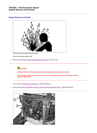
TS281-UN: Avoid High-Pressure Fluids
Disconnect negative battery cable.
2. Remove counterweight. See Counterweight Remove and Install . (Group 1749.)
3.
CAUTION:
Explosive release of fluids from pressurized cooling system can cause serious burns.
Shut off engine. Remove filler cap when cool to touch. Slowly loosen filler cap to first stop to relieve
pressure, then remove.
Drain coolant. See Draining Cooling System . (Operator's Manual.)
4. Drain hydraulic fluid. See Changing Hydraulic Tank Oil and Cleaning Suction Screen . (Operator's Manual.)
5.
1/5
2019/11/18file:///C:/ProgramData/Service%20ADVISOR/Temp/TM2356_09001faa80ca...
2. T207062A-UN: Engine Frame
T207063A-UN: Coolant hoses
LEGEND:
1 - Cap Screw (2 used)
2 - Left-Side Frame Bracket
3 - Left-Rear Frame Bracket
4 - Right-Rear Frame Bracket
5 - Frame Cover
6 - Frame Cover
7 - Right-Side Frame Bracket
8 - Fan Guard
9 - Coolant Hoses
10 - Inlet Fuel Line
11 - Return Fuel Line
12 - Speed Control Cable
13 - Ground Strap
Remove two cap screws (1) holding air cleaner housing.
6. NOTE:
Note any shims that may accompany frame brackets for installation.
Remove frame brackets (2-4) and frame cover (5).
7. Remove right-side frame bracket (7).
8. Remove air cleaner assembly.
9. Remove coolant fan guard (8) and coolant hoses (9).
10. Remove radiator. See Radiator Remove and Install (S.N. —254999) or see Radiator Remove and Install (S.N. 255000— ) . (Group
0510.)
11. Remove fan belt and fan.
12. Disconnect the inlet (10) and return (11) fuel lines.
13. Disconnect speed control cable (12) from engine.
14. Disconnect ground strap (13).
2/5
2019/11/18file:///C:/ProgramData/Service%20ADVISOR/Temp/TM2356_09001faa80ca...
4. 22 - Engine Mount Cap Screw and Washer (4 used)
Disconnect hydraulic pump hose (14) and inlet flange (15).
16. Remove two cap screws (16) and pull hydraulic pump (17) away from engine until drive coupler is disengaged from flywheel and
housing.
17. Disconnect wire harnesses from alternator (18) and starter motor (19).
18. Remove starter motor.
19. Remove two cap screws (20) and fasteners under starter motor securing wiring harness to engine block.
20. Disconnect wiring harnesses from fuel shut-off solenoid, switches, and sensors. Attach identification tags to wiring to aid installation.
See Engine Harness (W10) Component Location . (Group 9015.)
21.
CAUTION:
Prevent possible injury from crushing. Heavy component, use appropriate lifting device.
IMPORTANT:
The recommended method for lifting the engine is using the JDG23 Lifting Sling. The lifting force must be at 90° to the
lifting points.
Attach engine to a hoist using the JDG23 Lifting Sling (21).
22. Remove engine mount cap screws and washers (22).
23. Repair or replace parts as necessary.
24. Install engine using JDG23 Lifting Sling (21).
25. Install four engine mounts and cap screws (22). Tighten to specifications.
26. Align hydraulic pump splines to engine coupler. Tighten to specifications.
27. Connect inlet flange and hydraulic hose to pump. Tighten to specifications.
28. Fill hydraulic system.
29. Bleed hydraulic system. See Bleed Hydraulic System . (Operator's Manual.)
30. NOTE:
Item Measurement Specification
Engine Weight 199 kg
440 lb
Item Measurement Specification
Engine Mount-to-Isolator Cap
Screw
Torque 88 N˙m
65 lb-ft
Item Measurement Specification
Hydraulic Pump-to-Flywheel
Housing Cover Cap Screws
Torque 88 N m
65 lb-ft
Item Measurement Specification
Inlet Flange-to-Hydraulic Pump Torque 48 N˙m
36 lb-ft
4/5
2019/11/18file:///C:/ProgramData/Service%20ADVISOR/Temp/TM2356_09001faa80ca...
5. Before installing starter motor, install two cap screws and fasteners under starter, securing wiring harness to
engine block.
Install starter motor.
31. Connect engine wire harness. See Engine Harness (W10) Component Location . (Group 9015.)
32. Connect speed control cable to engine.
33. Install ground strap to frame.
34. Install fan and fan belt.
35. Adjust fan belt tension. See Inspect Fan Belt, Check and Adjust Tension . (Operator's Manual.)
36. Install radiator. See Radiator Remove and Install (S.N. —254999) or see Radiator Remove and Install (S.N. 255000— ) . (Group
0510.)
37. Fill radiator and reservoir with coolant. See Cooling System Fill and Deaeration . (Operator's Manual.)
38. Install air cleaner assembly.
39. NOTE:
Make note of any shims that were removed in the disassembly process, and place in same location of removal.
Attach frame brackets to frame.
40. Attach two cap screws from the upper frame bracket-to-air cleaner.
41. Bleed fuel system. See Bleed Fuel System . (Group 0560.)
42. Install counterweight. See Counterweight Remove and Install . (Group 1749.)
43. Connect the negative battery cable.
TW73308,000043C-19-20090219
5/5
2019/11/18file:///C:/ProgramData/Service%20ADVISOR/Temp/TM2356_09001faa80ca...
9. 4. Remove exhaust pipe clamp (2).
5. Remove heat shields to muffler (3) and exhaust manifold (4).
6. Remove four muffler-to-exhaust manifold nuts (5) and washers.
7. Remove muffler bracket cap screw (6) and remove muffler.
8. Install muffler gasket and muffler.
9. Install muffler bracket cap screw (6).
10. Install muffler-to-exhaust manifold nuts (5) and tighten.
11. Install heat shields to exhaust manifold (4) and muffler (3).
12. Install exhaust pipe clamp (2).
13. Install counterweight and left-side panels. See Counterweight Remove and Install . (Group 1749.)
MM61211,0000A43-19-20060103
2/2
2019/11/18file:///C:/ProgramData/Service%20ADVISOR/Temp/TM2356_09001faa802c...
10. TM2356 - 27D Excavator Repair
Thermostat Remove and Install
Thermostat Remove and Install
M82315A-UN: Thermostat
LEGEND:
A - Cap Screw
B - Cover
C - Cover Gasket
D - Thermostat
E - Gasket
1. Drain engine coolant. See Draining Cooling System . (Operator's Manual.)
2. Remove cap screws (A).
3. Remove cover (B), cover gasket (C), thermostat (D), and gasket (E).
4. Test thermostat. See Engine Thermostat Test . (Group 9010-25.)
5. At installation, replace gaskets.
Item Measurement Specification
Thermostat Cover Cap Screw Torque 20 N˙m
15 lb-ft
OUO1030,00000BC-19-20060105
1/1
2019/11/18file:///C:/ProgramData/Service%20ADVISOR/Temp/TM2356_09001faa802a...
11. TM2356 - 27D Excavator Repair
Water Pump Remove and Install
Water Pump Remove and Install
RG8583A-UN: Water Pump
LEGEND:
A - Water Pump
B - Fan-to-Water Pump Cap Screw (4 used)
C - Fan
D - Spacer
E - Pulley
F - Fan Belt
G - Water Pump-to-Cylinder Head Cap Screw (4 used)
H - Gasket
I - O-Ring
J - Gasket
K - Ball Joint
L - Cap Screw (3 used)
1. Remove radiator. See Radiator Remove and Install . (Group 0510.)
2. Remove thermostat and cover. See Thermostat Remove and Install . (Group 0400.)
3. Disconnect coolant temperature sensor leads.
4. Disconnect upper and lower radiator hoses.
5. Remove fan belt (F).
6. Remove cap screws (B), fan (C), spacer (D), and pulley (E).
7. Remove mounting cap screws (G), water pump (A), and gasket (H).
8. Remove cap screws (L), ball joint (K), gasket (J), and O-ring (I).
9. Installation is done in the reverse order of removal.
1/2
2019/11/18file:///C:/ProgramData/Service%20ADVISOR/Temp/TM2356_09001faa802c...
12. Thank you very much for
your reading. Please Click
Here. Then Get COMPLETE
MANUAL. NO WAITING
NOTE:
If there is no response to
click on the link above,
please download the PDF
document first and then
click on it.
13. IMPORTANT:
At installation, replace all O-rings and copper washers.
10. Adjust fan belt tension. See Inspect Fan Belt, Check and Adjust Tension . (Operator's Manual.)
11. IMPORTANT:
Air must be expelled from cooling system when system is filled. Loosen coolant temperature sender or plug in thermostat housing
to allow air to escape when filling system. Tighten sender or plug when all the air has been expelled.
Close drain valve and remove coolant temperature sender from engine. Fill radiator with proper coolant until coolant is present at temperature
sender hole. Install temperature sender and continue to fill radiator to top of filler neck.
Item Measurement Specification
Water Pump Mounting Cap Screws Torque 26 N˙m
230 lb-in.
Water Pump-to-Fan Mounting Cap
Screws
Torque 11 N˙m
97 lb-in.
Water Pump Plug Torque 15 N˙m
132 lb-in.
MM61211,0000A44-19-20060103
2/2
2019/11/18file:///C:/ProgramData/Service%20ADVISOR/Temp/TM2356_09001faa802c...
14. TM2356 - 27D Excavator Repair
Intake Manifold Remove and Install
Intake Manifold Remove and Install
T217247A-UN: Intake Manifold
LEGEND:
1 - Breather Tube
2 - Fuel Injection Lines
3 - Intake Manifold Cap Screw (4 used)
4 - Fuel Filter Bracket
5 - Final Fuel Filter Housing
6 - Terminal Connection
1. Remove counterweight. See Counterweight Remove and Install . (Group 1749.)
2. Disconnect crankcase breather tube (1).
3. IMPORTANT:
Never steam clean or pour cold water on injection pump while the pump is running or warm. Doing so
can damage the pump.
Clean the injection pump lines and area around the nozzles using a parts cleaning solvent or steam cleaner.
4. Loosen fuel injection line (2) connectors-to-nozzles slightly to release pressure in the fuel system.
5. Remove fuel injection lines.
6. Disconnect fuel filter bracket (4) from intake manifold.
7. Disconnect final fuel filter housing (5) from intake manifold.
8. Disconnect air intake heater terminal (6).
1/2
2019/11/18file:///C:/ProgramData/Service%20ADVISOR/Temp/TM2356_09001faa802c...
15. 9. Remove intake manifold cap screws (3).
10. Remove intake manifold.
11. Clean cylinder head and intake manifold mounting surfaces.
12. Install intake manifold using new gasket.
13. Tighten cap screws to specification.
14. Connect air intake heater terminal.
15. Connect both fuel filters to intake manifold.
16. Install fuel injection lines.
17. Connect crankcase breather tube.
Item Measurement Specification
Intake Manifold Cap Screws Torque 11 N˙m
97 lb-in.
MM61211,0000A45-19-20060103
2/2
2019/11/18file:///C:/ProgramData/Service%20ADVISOR/Temp/TM2356_09001faa802c...