
Recommended
Recommended
More Related Content
Similar to Caterpillar Cat 215B EXCAVATOR (Prefix 2XC) Service Repair Manual Instant Download.pdf
Similar to Caterpillar Cat 215B EXCAVATOR (Prefix 2XC) Service Repair Manual Instant Download.pdf (14)
More from fujskekkdm8ik
More from fujskekkdm8ik (17)
Recently uploaded
Recently uploaded (20)
Caterpillar Cat 215B EXCAVATOR (Prefix 2XC) Service Repair Manual Instant Download.pdf
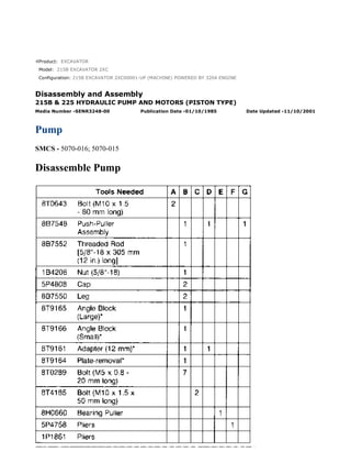
- 1. Product: EXCAVATOR Model: 215B EXCAVATOR 2XC Configuration: 215B EXCAVATOR 2XC00001-UP (MACHINE) POWERED BY 3204 ENGINE Disassembly and Assembly 215B & 225 HYDRAULIC PUMP AND MOTORS (PISTON TYPE) Media Number -SENR3248-00 Publication Date -01/10/1985 Date Updated -11/10/2001 Pump SMCS - 5070-016; 5070-015 Disassemble Pump 1/20 215B EXCAVATOR 2XC00001-UP (MACHINE) POWERED BY 3204 ENGINE(SE... 2020/12/28 https://127.0.0.1/sisweb/sisweb/techdoc/techdoc_print_page.jsp?returnurl=/sis...
- 2. START BY: a. remove pump 1. Cover all pump openings, and clean the outside of the pump thoroughly. NOTICE There are four external adjustment screws on this pump. All four adjustment screws have protective covers to prevent tampering or accidental adjustment. The covers will be destroyed and will need to be replaced if they are removed. The covers should be removed only when necessary for proper pump disassembly. Changes should be made to the adjustment screws only by trained personnel or poor vehicle performance will result. 2. Remove the plastic covers from power adjustment screw (2) and torque adjustment screw (1). 2/20 215B EXCAVATOR 2XC00001-UP (MACHINE) POWERED BY 3204 ENGINE(SE... 2020/12/28 https://127.0.0.1/sisweb/sisweb/techdoc/techdoc_print_page.jsp?returnurl=/sis...
- 3. 3. Measure the height (dimension X) of torque adjustment screw (1) from the machined surface under the locking nut to the top of the screw. Record the dimension. 4. Measure the height of power adjustment screw (2) from the pump housing surface to the top of the screw. Record the dimension. NOTICE Do not loosen power adjustment screw (2) or the jam nut. Remove only the threaded sleeve that the power adjustment screw threads into, and the adjustment will not be lost. 5. Remove the threaded sleeve on power adjustment screw (2). Use a magnet, and remove the spring and spring seat from the pump housing. When the threaded sleeve is removed, the entire power adjustment screw assembly can be removed from the pump housing without changing the adjustment. 6. Loosen the jam nut for torque adjustment screw (1) 1/2 of a revolution. Remove the torque adjustment screw from the pump housing. The adjustment screw can be replaced into its original position at assembly by using the measurement that was determined in Step 4. 7. Put alignment marks on control housing (3) and pump housing (5) for correct assembly. 8. Remove 12 bolts (4) that hold the control housing to the pump housing. 9. Remove control housing (3) from pump housing (5). It may be necessary to carefully pry the control housing off of the two alignment dowels that are between the two housings. 10. Clean the gasket from control housing (3) and pump housing (5). 3/20 215B EXCAVATOR 2XC00001-UP (MACHINE) POWERED BY 3204 ENGINE(SE... 2020/12/28 https://127.0.0.1/sisweb/sisweb/techdoc/techdoc_print_page.jsp?returnurl=/sis...
- 4. 11. Put identification marks on control housing (3) and two control plates (6) and (7). Also put marks on the control plates to indicate the correct position of the dampening slots. 12. Remove control plates (6) and (7) from the control housing. 13. Remove bolt (10), spacer (11), and spring (12) that hold control lever assembly (8) to the control housing. Also, remove the spring under the other end of the control lever assembly. Bolt (10) was installed with thread lock, so it may be difficult to remove. 14. Remove spring seat (9) from control lever assembly (8). 15. Remove control spool and roller assembly (13). 16. Put alignment marks on maximum angle stop housing (14) and the control housing for assembly purposes. 17. Remove four bolts (15) and maximum angle stop housing (14) from the control housing. Remove the two O-ring seals from maximum angle stop housing (14). 18. Remove retaining ring (16) from control spool and roller assembly (13). Remove shaft (17) and roller bearing (18). 4/20 215B EXCAVATOR 2XC00001-UP (MACHINE) POWERED BY 3204 ENGINE(SE... 2020/12/28 https://127.0.0.1/sisweb/sisweb/techdoc/techdoc_print_page.jsp?returnurl=/sis...
- 5. 19. Remove plugs (19) and (21). Remove the inner and outer pressure averaging valve spools behind plug (19). 20. Remove two plugs (20). Remove the relief valve and spring behind each plug. Remove the O- ring seals on plugs (20). 21. Put alignment marks on pressure averaging valve housing (23) and the control housing for assembly purposes. There is spring pressure behind pressure averaging valve housing (23) which may cause the assembly to fly apart when the two bolts are removed. To prevent possible personal injury, longer bolts should be used to release the spring pressure. 22. Remove one bolt (22), and install one bolt from tooling (A). Remove bolt (24), and install the other bolt from tooling (A). Loosen the two bolts from tooling (A) evenly, and release the spring pressure behind pressure averaging valve housing (23). 23. Remove tooling (A), and remove pressure averaging valve housing (23). Remove the three O- ring seals from the housing. 24. Remove control spool bushing (25). 25. Remove spring (26) from the control cover. 5/20 215B EXCAVATOR 2XC00001-UP (MACHINE) POWERED BY 3204 ENGINE(SE... 2020/12/28 https://127.0.0.1/sisweb/sisweb/techdoc/techdoc_print_page.jsp?returnurl=/sis...
- 6. 26. Note the location of pilot oil bore hole (27) in the end of the control piston. Put identification marks on the control piston for assembly purposes. 27. Hold swivel fork (29) in position, and remove control piston (28). Remove swivel fork (29). Piston rings (30) and (31) may break apart during removal from the pistons. If the rings are to be removed, wear eye protection to prevent possible personal injury from flying parts. 28. Remove piston rings (30) and (31) from control piston (28). 6/20 215B EXCAVATOR 2XC00001-UP (MACHINE) POWERED BY 3204 ENGINE(SE... 2020/12/28 https://127.0.0.1/sisweb/sisweb/techdoc/techdoc_print_page.jsp?returnurl=/sis...
- 7. 29. Remove two cylinder blocks (32) by pulling straight up. When each cylinder block is removed, the spring collar and the Bellville washers will most likely fall out of the center pin hole. Make sure that one spring collar (33) and four Bellville washers (34) are retrieved from the housing when each cylinder block is removed. Check the center pin hole in the cylinder block if all the parts did not fall out. 30. Remove 28 screws (35) that hold both retainer plates to the drive gears. The screws were installed with thread lock so they will be difficult to remove. Impact the screw heads first to break the seal, and remove by using additional leverage on the screwdriver as shown. 31. Remove the two retainer plates, 14 pistons (36) and the two center pins from the drive gear and bearing assembly. Piston rings (37) may break apart during removal from the pistons. If the rings are to be removed, wear eye protection to prevent possible personal injury from flying parts. 32. Use a screwdriver, and remove piston rings (37) from pistons (36). 7/20 215B EXCAVATOR 2XC00001-UP (MACHINE) POWERED BY 3204 ENGINE(SE... 2020/12/28 https://127.0.0.1/sisweb/sisweb/techdoc/techdoc_print_page.jsp?returnurl=/sis...
- 8. 33. Use tooling (B), and remove the drive gear and bearing assembly. Use the same tooling to remove the other drive gear and bearing assembly. Remove tooling (B). 34. Remove four bolts (38). 35. Use tooling (C), and remove cover (39) from the pump housing. Remove the O-ring seal from cover (39). 36. Install tooling (D). Remove the auxiliary drive gear and bearings as an assembly. Remove tooling (D). 37. Use tooling (E) and a press to remove two bearings (41) from gear (40). 8/20 215B EXCAVATOR 2XC00001-UP (MACHINE) POWERED BY 3204 ENGINE(SE... 2020/12/28 https://127.0.0.1/sisweb/sisweb/techdoc/techdoc_print_page.jsp?returnurl=/sis...
- 9. 38. Use tool (F), and remove retaining ring (42). Remove the spacer ring and the O-ring seal behind retaining ring (42). 39. Put a small pry bar in the slot around the top, and remove cover (43) from the pump housing. 40. Remove the lip-type seal from cover (43). 41. Use tool (G), and remove retaining ring (44). Remove the spacer ring and the O-ring seal behind retaining ring (44). 42. Use a small pry bar in the slot around the top, and remove cover (45). 43. Install tooling (H) on the idler gear shaft. Use a torch, and heat the idler gear evenly to a temperature of 80°C (176°F). Remove the idler gear shaft from the gear, the inner bearing, and from the pump housing. 44. Remove the idler gear from the pump housing. 45. Remove the key from the idler gear shaft. 46. Remove the outer bearing from the idler gear shaft. 47. Remove the inner bearing from the pump housing. Assemble Pump 9/20 215B EXCAVATOR 2XC00001-UP (MACHINE) POWERED BY 3204 ENGINE(SE... 2020/12/28 https://127.0.0.1/sisweb/sisweb/techdoc/techdoc_print_page.jsp?returnurl=/sis...
- 10. 1. Measure the center pins, spring collar, cylinder block, and control plate to determine the proper size spring collar that should be used for assembly. Refer to the Testing And Adjusting Manual for the adjustment procedure. The Testing And Adjusting Manual, Form Nos. are SENR3109 for the 215B Excavator and SENR3110 for the 225 Excavator. NOTICE To prevent damage to the idler gear shaft inner bearing force should be applied only to the outer race when it is installed. 2. Lower the temperature of the lower idler gear shaft ball bearing. Use a hammer and a soft punch, and install the lower idler gear shaft ball bearing into the pump housing. 3. Raise the temperature of the upper idler gear shaft bearing to 80°C (176°F), and install it onto the idler gear shaft. Make sure the bearing is seated on the shaft and does not bounce back when it is installed. Allow the bearing and shaft to cool. 4. Install the key onto the idler gear shaft. 5. Raise the temperature of the idler gear to 100°C (212°F). Put it into position in the pump housing with the shoulder toward the lower bearing. 10/20 215B EXCAVATOR 2XC00001-UP (MACHINE) POWERED BY 3204 ENGINE(... 2020/12/28 https://127.0.0.1/sisweb/sisweb/techdoc/techdoc_print_page.jsp?returnurl=/sis...
- 11. 6. Align the slot in the idler gear with the key on idler gear shaft (1). Use a hammer and soft punch, and install idler gear shaft (1) and upper bearing (2) into the idler gear and the lower bearing that are in position in the pump housing. 7. Install cover (4) into the pump housing. Put O-ring seal (3) on top of the cover, and put spacer (5) in position on top of the O-ring seal. 8. Use tool (A), and install retaining ring (6). NOTICE All piston rings must be installed with the marks toward the flat end of the piston, or the motor will not operate. 9. The piston rings are spherical and must be installed with the marks toward the flat end of pistons (8). Use tooling (B), and install two piston rings (7) on each piston (8). Rotate the piston ring end gaps to be 180° apart. Repeat this procedure for the 14 pistons. 11/20 215B EXCAVATOR 2XC00001-UP (MACHINE) POWERED BY 3204 ENGINE(... 2020/12/28 https://127.0.0.1/sisweb/sisweb/techdoc/techdoc_print_page.jsp?returnurl=/sis...
- 12. 10. Put seven pistons (8), center pin (9) and the retaining plate in position on the drive gear and bearing assembly. Use 6V1541 Quick Cure Primer on 14 screws (10) and allow them to dry. Put 9S3263 Thread Lock on 14 screws (10). Install the screws, and tighten them to a torque of 6 N·m (53.4 lb.in.). Repeat the step for the other drive gear and bearing assembly. 11. The spring collar that was selected in Step 1 should be used at this time. Put spring collar (12) and four Bellville washers (13) in the order and direction shown. Use 5P960 Multipurpose Grease to hold them in position. Use a screwdriver, and put spring collar (12) and Bellville washers (13) into the center pin bore of cylinder block (11). Repeat the step for the other cylinder block. 12. Put SAE 10W oil on seven pistons (8) and the center pin. Also, put SAE 10W oil on the piston bores of the cylinder block. Make sure the Bellville washers stay in the proper position in the cylinder block. Repeat the step for the other cylinder block. 13. Align seven pistons (8) and the center pin with their respective bores in the cylinder block, and assemble the unit. The assembled unit is called a rotary group. Repeat this step to assemble the other rotary group. NOTICE The outer diameters of rotary group bearings (14) and the pump housing bores must be clean and dry when the rotary groups are installed. 12/20 215B EXCAVATOR 2XC00001-UP (MACHINE) POWERED BY 3204 ENGINE(... 2020/12/28 https://127.0.0.1/sisweb/sisweb/techdoc/techdoc_print_page.jsp?returnurl=/sis...
- 13. 14. Raise the temperature of pump housing (15) to 80°C (176°F). Put the pump housing on wood blocks so the drive shaft will have clearance when it is installed. Align rotoray group gear (16) with the idler gear, and install the rotary group into the pump housing. NOTICE There are timing marks (18) on two rotary group gears (16) and (17). The timing marks must be aligned as the rotary groups are installed into the pump housing. 15. Align the timing mark on rotary group gear (17) with the timing mark on rotary group gear (16). Install the rotary group into the pump housing. Two timing marks (18) should be aligned as shown. NOTE: Complete Step 16 and Step 17 while the pump housing is still warm to make assembly easier. 13/20 215B EXCAVATOR 2XC00001-UP (MACHINE) POWERED BY 3204 ENGINE(... 2020/12/28 https://127.0.0.1/sisweb/sisweb/techdoc/techdoc_print_page.jsp?returnurl=/sis...
- 14. NOTICE To prevent damage to inner bearing (20), force should be applied only to the inner race when it is installed onto the gear. 16. Use a hammer and soft punch, and install inner bearing (20) onto auxiliary drive gear (19). 17. While pump housing (15) is still warm, install auxiliary drive gear (19) and the inner bearing into the pump housing. 18. Raise the temperature of outer bearing (21) to 80°C (176°F). Use a hammer and soft punch, and install the bearing onto auxiliary drive gear (19). 19. Install the O-ring seal on flange (22), and put it into position on the pump housing. Install four bolts (23) into the flange and pump housing. Tighten the bolts to a torque of 86 N·m (65 lb.ft.). Piston rings (24) and (26) may break apart during installation onto control piston (25). Use care when expanding the piston rings. Wear eye protection to prevent possible personal injury from flying parts. 14/20 215B EXCAVATOR 2XC00001-UP (MACHINE) POWERED BY 3204 ENGINE(... 2020/12/28 https://127.0.0.1/sisweb/sisweb/techdoc/techdoc_print_page.jsp?returnurl=/sis...
- 15. 20. Install piston rings (24) and (26) onto control piston (25). 21. Put swivel fork (28) into position in control cover (27) with the machined shoulder toward the small diameter of the control piston. Put SAE 10W oil on control piston (25). Install it into the control cover and the swivel fork. Make sure the control piston is installed correctly with the pilot oil hole toward the pump housing mounting surface. 22. Install control spool bushing (29) into the control piston. Install spring (30). Make sure the spring goes against the machined shoulder of swivel fork (28). NOTE: Plugs (31) and (34) have an integral seal. If the seals on plugs (31) and (34) need to be replaced, the entire plug (31) or (34) must be replaced. 23. Install inner pressure averaging valve spool (38) into outer pressure averaging valve spool (33). Install both valve spools into pressure averaging valve housing (32). Install two plugs (31) and (34) into the pressure averaging valve housing. 24. Install the O-ring seals onto plugs (35). Put two relief valves (37) and springs (36) into plugs (35). Install them into the pressure averaging valve housing. 15/20 215B EXCAVATOR 2XC00001-UP (MACHINE) POWERED BY 3204 ENGINE(... 2020/12/28 https://127.0.0.1/sisweb/sisweb/techdoc/techdoc_print_page.jsp?returnurl=/sis...
- 16. 25. Use 5P960 Multipurpose Grease, and put two O-ring seals (39) into position on pressure averaging valve housing (32). 26. Install O-ring seal (40) onto the pressure averaging valve housing. Put 5P960 Multipurpose Grease on O-ring seal (40) and the pressure averaging valve housing tube. Use tooling (C) to compress the spring behind pressure averaging valve housing (32). Remove the long bolts, and install the standard bolts one at a time to maintain the pressure on the spring. To prevent possible personal injury, do not remove two bolts (41) at the same time and allow the assembly to fly apart. 27. Put pressure averaging valve housing (32) into position on the control cover (27). Use tooling (C), and compress the spring behind the housing. Install standard bolts (41) one at a time to maintain the spring compression. Tighten bolts (41) to a torque of 69 N·m (50 lb.ft.). 28. Put bearing (45) into position in control spool (42). Install pin (43), and secure it with retaining ring (44). 16/20 215B EXCAVATOR 2XC00001-UP (MACHINE) POWERED BY 3204 ENGINE(... 2020/12/28 https://127.0.0.1/sisweb/sisweb/techdoc/techdoc_print_page.jsp?returnurl=/sis...
- 17. 29. Use 5P960 Multipurpose Grease, and put two O-ring seals (47) in position on maximum angle stop housing (46). 30. Put maximum angle stop housing (46) in position on the control cover, and install four bolts (49). Tighten four bolts (49) to a torque of 86 N·m (65 lb.ft.). 31. Install control spool and roller assembly (48) into control spool bushing (29). 32. Put 9S3263 Thread Lock on spring seat (51), and install it onto control lever assembly (50). 33. Put 9S3263 Thread Lock on bolt (52), and put it into position with spacer (53), and spring (54) on control lever assembly (50). 17/20 215B EXCAVATOR 2XC00001-UP (MACHINE) POWERED BY 3204 ENGINE(... 2020/12/28 https://127.0.0.1/sisweb/sisweb/techdoc/techdoc_print_page.jsp?returnurl=/sis...
- 18. 34. Put spring (55) in position under the control lever assembly. Put control lever assembly (50) in position on the control cover. Make sure spring (55) stays in position and the holes in the control lever are aligned with two dowels (56). Install bolt (52) into the control cover, and tighten it to a torque of 10 N·m (90 lb.in.). NOTICE Control plates (58) must be installed correctly or the pump will not operate. 35. Use 5P960 Multipurpose Grease, and put two control plates (58) in position on the swivel fork in the control cover. Make sure the inlet ports are toward the center and dampening slots (57) are positioned as shown. NOTICE The cylinder blocks must be aligned with the control plates or the pump will be damaged when bolts (60) are tightened. 18/20 215B EXCAVATOR 2XC00001-UP (MACHINE) POWERED BY 3204 ENGINE(... 2020/12/28 https://127.0.0.1/sisweb/sisweb/techdoc/techdoc_print_page.jsp?returnurl=/sis...
- 19. 36. Put gasket (59) in position on the pump housing. 37. Tilt both cylinder blocks to the maximum angle, and put control cover (27) in position onto the pump housing. Make sure the cylinder blocks are aligned with the control plates. Check the cylinder block and control plate alignment if the control cover does not go over the alignment pins easily. 38. Install 12 bolts (60) into the pump housing. Tighten them to a torque of 86 N·m (65 lb.ft.). 39. Install the O-ring seal on power adjustment screw (62). Put spring (63) and spring seat (61) in position on power adjustment screw (62). 40. Install power adjustment screw (62) with the spring and spring seat into the pump housing. Measure the height of the adjustment screw, and compare it with the dimension that was measured in Step 4 of Disassemble Pump. The dimension should be the same. 41. Install torque adjustment screw (64) into the pump housing, and tighten the locking nut so the height of the adjustment screw is the same dimension that was measured in Step 3 of Disassemble Pump. NOTE: If the drive shaft is grooved at the seal contact area, shim material up to 1.00 mm (.040 in.) maximum thickness may be used between lip-type seal (66) and cover (65). 42. Use tooling (D), and install lip-type seal (66) in drive shaft cover (65). Put SAE 10W oil on the lip of the seal. 19/20 215B EXCAVATOR 2XC00001-UP (MACHINE) POWERED BY 3204 ENGINE(... 2020/12/28 https://127.0.0.1/sisweb/sisweb/techdoc/techdoc_print_page.jsp?returnurl=/sis...
- 20. 43. Use 5P960 Multipurpose Grease, and put O-ring seal (67) in position. 44. Install tool (E) over the drive shaft to protect the lip-type seal. 45. Install cover (68) into the housing. It may be necessary to tap the cover into position. 46. Use tool (F), and install retaining ring (69). 47. Install the plastic covers on the power adjustment screw and the torque adjustment screw after the pump has been installed and adjusted on the vehicle. END BY: a. install pump 20/20 215B EXCAVATOR 2XC00001-UP (MACHINE) POWERED BY 3204 ENGINE(... 2020/12/28 https://127.0.0.1/sisweb/sisweb/techdoc/techdoc_print_page.jsp?returnurl=/sis...
- 21. Product: EXCAVATOR Model: 215B EXCAVATOR 2XC Configuration: 215B EXCAVATOR 2XC00001-UP (MACHINE) POWERED BY 3204 ENGINE Disassembly and Assembly 215B & 225 HYDRAULIC PUMP AND MOTORS (PISTON TYPE) Media Number -SENR3248-00 Publication Date -01/10/1985 Date Updated -11/10/2001 Motors (Swing And Track) SMCS - 5058-015; 5058-016 Disassemble Motors (Swing And Track) NOTE: There are several sizes of the bent axis type motors. Only one size of motor is shown here, however, the disassembly and assembly remains the same for all sizes. Special tools that are needed for a particular size of motor are identified in the tool chart by motor type. It is necessary to see two tool charts for a complete listing. Special tools are common for all motors are listed in the first tool chart. Special tools for a particular size of motor are identified in the other tool charts by motor type. 1/14 215B EXCAVATOR 2XC00001-UP (MACHINE) POWERED BY 3204 ENGINE(SE... 2020/12/28 https://127.0.0.1/sisweb/sisweb/techdoc/techdoc_print_page.jsp?returnurl=/sis...
- 22. START BY: a. remove track motor b. remove swing motor 1. Put plugs in the open oil passages. Clean the outside of the motor thoroughly. 2/14 215B EXCAVATOR 2XC00001-UP (MACHINE) POWERED BY 3204 ENGINE(SE... 2020/12/28 https://127.0.0.1/sisweb/sisweb/techdoc/techdoc_print_page.jsp?returnurl=/sis...
- 23. 2. Remove the plugs from two case drain holes (1). Drain any oil from the motor that remains. 3. Put tape around splined drive shaft (2) to prevent damage to the drive shaft or seals during disassembly of the motor. 4. Tap the cover with a plastic hammer to release some of the pressure against retaining ring (3). Use tool (A), and remove retaining ring (3). 5. Use two screw drivers, and remove front cover (4). Remove the O-ring seal and the shims that are behind front cover (4). NOTE: Pump drive shaft seal (5) will be destroyed if it is removed from front cover (4). 6. Remove lip-type seal (5) from the front cover. 3/14 215B EXCAVATOR 2XC00001-UP (MACHINE) POWERED BY 3204 ENGINE(SE... 2020/12/28 https://127.0.0.1/sisweb/sisweb/techdoc/techdoc_print_page.jsp?returnurl=/sis...
- 24. 7. Turn the motor around, and put alignment marks on the rear cover plate and the motor housing for assembly purposes. 8. Remove six bolts (6) and lockwashers that hold the rear cover plate to the motor housing. 9. Rotate rear cover plate (7) on the locating pin, and remove it from the motor housing. 10. Note the position of locating pin hole (9) on the control plate that the locating pin in rear cover plate (7) was removed from. 11. Remove O-ring seal (8) from the motor housing. 12. Remove control plate (11) from motor housing (12). Note the condition of the bronze surface on cylinder block (10) and the mating surface of control plate (11). 4/14 215B EXCAVATOR 2XC00001-UP (MACHINE) POWERED BY 3204 ENGINE(SE... 2020/12/28 https://127.0.0.1/sisweb/sisweb/techdoc/techdoc_print_page.jsp?returnurl=/sis...
- 25. NOTICE Use only a puller such as tooling (B) to remove the rotary group. Do not use a slidehammer type puller or damage to the motor may result. 13. Use tooling (B), and remove the rotary group from motor housing (12). Make sure cylinder block (10) does not bind as it is pulled through the motor housing. 14. Remove tooling (B) from rotating group (13). 15. Pull cylinder block (10) from the drive shaft and piston assembly (14). 16. Remove four Bellville washers (16) and spring collar (15) from the center pin bore of cylinder block (10). 5/14 215B EXCAVATOR 2XC00001-UP (MACHINE) POWERED BY 3204 ENGINE(SE... 2020/12/28 https://127.0.0.1/sisweb/sisweb/techdoc/techdoc_print_page.jsp?returnurl=/sis...
- 26. 17. Use a section of pipe or wood blocks, and put the drive shaft and piston assembly in position as shown. 18. Position each piston (18) perpendicular to retaining plate (17), and remove them by pulling straight out. Do this for the seven pistons. The center pin cannot be removed at this time. 19. Check seven pistons (18) at area (X) for scratches and pitting. Make replacements if necessary. Piston rings (19) may break apart during removal from the pistons. If the rings are to be removed, wear eye protection to prevent possible personal injury from flying parts. 20. Use a screwdriver, and remove piston rings (19) from the piston. 21. Remove seven screws (21) that hold retainer plate (17) to the drive shaft assembly. The screws were installed with Thread Lock so they will be difficult to remove. Impact the screw heads first to break the seal, and remove by using additional leverage on the screwdriver as shown. 22. Remove retainer plate (17), center pin (20) and the ring that holds the center pin in place. 6/14 215B EXCAVATOR 2XC00001-UP (MACHINE) POWERED BY 3204 ENGINE(SE... 2020/12/28 https://127.0.0.1/sisweb/sisweb/techdoc/techdoc_print_page.jsp?returnurl=/sis...
- 27. Suggest: If the above button click is invalid. Please download this document first, and then click the above link to download the complete manual. Thank you so much for reading
- 28. 23. Check center pin (20) for scratches or pitting at areas (Y). Replace the center pin if necessary. Assemble Motors (Swing And Track) NOTE: There are several sizes of the bent axis type motors. Only one size of motor is shown here, however, the disassembly and assembly remains the same for all sizes. It is necessary to see two tool charts for a complete listing. Special tools for a particular size of motor are identified in the first four tool charts by motor type. Special tools that are common for all motors are listed in the last tool chart. 7/14 215B EXCAVATOR 2XC00001-UP (MACHINE) POWERED BY 3204 ENGINE(SE... 2020/12/28 https://127.0.0.1/sisweb/sisweb/techdoc/techdoc_print_page.jsp?returnurl=/sis...