2. 16-2
16-2
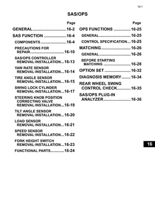
GENERAL
SAS (System of Active Stability) /OPS (Operator Presence Sensing) system configuration
Sensors are installed at each point of the vehicle to detect the vehicle movement and send signals to the controllers.
These signals are controlled by the controllers, and sent to each actuator to be operated.
(1)
S T K
Control
Control
S
T
K
O
S,T
K,O
Actuator
Sensor
O
(2)
(3)
(4)
(5)
(6)
(7)
(8)
(9)
(10)
(11)
(12)
(13)
(14)
Fork height switch
Swing lock cylinder
(Single tire only)
Tilt control valve
Lift lock valve
Knob position correcting
valve
Error lamp
Error code display
S:Rear wheel swing control
T :Mast tilting control
K:Steering knob position control
O:OPS control
Forward interrupt relay
Backward interrupt relay
Unload valve
Lift lock valve
Backward tilt lock valve
(Standard lever vehicle only)
OPS lamp
Buzzer
Tilt control valve
Tilt angle sensor
Forward tilt switch
Backward tilt switch
Lower switch
Load sensor
Fork automatic
leveling switch
Speed sensor
Steering wheel
angle sensor
Tire angle sensor
Yaw rate sensor
Seat switch
Forward switch
Backward switch
Controller
Input
Output
S,T
K,O
S,T
K,O
Plug-in anallyzer (SST)
Multifunction display (OPT)
(Bilt-in analyzer)
Output
5. 16-5
0
1
2
3
4
5
6
7
8
9
10
11
12
13
14
15
16
17
18
19
20
21
E
Tire Angle Sensor
Swing Lock Cylinder
4301
4301
4301-241
(RR SIDE RING)
44
44C
44D
Refer to
FIG. 4302
(STR-PIN BOOTS)
01
45
44E
44G
44
44D
44C
44H
44B
44A 44F
EK
42A
AC
41
42E
42C
42B
DY
JC
BX
AU
AB
HJ
42C
42[LH]
AC
20 EV
CG
EV
CG
AB
42[RH]
42C
BP
AO
EZ
AS
AT
CD
CD
12
GB JB
EK
42A
AC
45
44G
44E
44D
44C
44
44H
44B
44A
44F
40
DY
JC
BX
42E
42C
42B
CL
DG
47[UPPER]
CK
CL
DG
CK
CP
CK
JS
IK JS
IK
Refer to
FIG. 4302
CP
CK
CL
DG
CL
DG
47[UPPER]
CK
CK
CP
CK
JS
IK
47[LOWER]
CP
CK
JS
IK
47[LOWER]
AC
01K=(INCL. )
Refer to
FIG. 4302
(STR-PIN BOOTS)
Tire angle sensor
4301-246
GH
GV
16 CF
GU
DN
BR
EJ
BU
20A
BQ
EF
GH
20B
20A
01
BR
EJ
BU
Swing lock cylinder
6. 16-6
16-6
Steering Knob Position Correcting Valve
Fork Height Switch (V Mast)
4507
5803
4507-287
GD
AY
GD
AY
07
55A
CD
AT
CD
LH
Refer to
4503-01
CD
AS
CD
AS Refer to
6705-01
BZ
55
AD
KL
BJ
49
49
BJ
CB
07
43
53
42
BJ
55A
GW
CE
JP
CH
BH
BH
CH
Refer to
FIG. 4302
Steering knob
position correcting
valve
5803-172
BY
10
BP
BX
64
AT
AV
AU
AV
AP
33
AS
CY
63
AR
62
AO
10
7. 16-7
Fork Height Switch (FV Mast)
Fork Height Switch (FSV Mast)
5803
5803
5803-209
DA
62
AS
64
65
AZ
BC
BE
AR
AU
AV
AP
AO
AV
AT
33
BV
10
BY
BX
AW
10
5803-207
BY
BX
AW
10
DA
62
AS
64
65
AZ
BC
BE
AR
AU
AV
AP
AO
AV
AT
33
BV
10
8. 16-8
16-8
Fork Height Switch (FSW Mast)
Tilt Angle Sensor
5803
5803
5803-205
AS
AW
BX
BY
10
62
BV
33
AT
AV
AP
AO
AV
AU
DA
65
64
AZ
AR
BE
BC
10
10. 16-10
16-10
PRECAUTIONS FOR REPAIR
Fully understand the functions of SAS/OPS before repairing it.
1. Preparation for repair
(1) When washing the vehicle, care should be taken not to
splash water directly to the electrical components.
Do not perform high pressure washing for the controller,
tilt angle sensor, yaw rate sensor, fork height switch, horn
button, meters, switches on the instrument panel and
electrical components and parts in the engine
compartment.
(2) Remove contamination and/or water from respective
sections.
(3) Transport the controllers or sensors in a packed state with cushions, and keep it packed until installation.
Never transport it in an exposed state. Also, do not apply mechanical shock on the controllers or sensors by
dropping or crashing them.
(4) Part number for a controller varies by the vehicle specifications. Check the correct part number in advance.
(5) If a repair work requires matching, always park the vehicle on a flat place.
(6) Arrange for necessary tools and measuring instrument (such as a plug-in analyzer (SST 09240-26600-71)
and circuit tester, etc.).
2. During repair
(1) Never use an impact wrench for removing and installing controllers and sensors.
(2) Do not turn the ignition key switch ON or OFF more than necessary when the sensor wiring is
disconnected. Turning the ignition key switch ON in this state causes an error and an error code will be
stored in the controller. The error code is not erasable and a maximum of ten errors will be stored. If 11 or
more error codes are stored, the oldest error code will be sequentially erased.
(3) When turning the solenoid (for lock cylinder, knob position correction valve) ON during an “Active Test” of
the analyzer, do not keep it ON for more than one (1) minute. Since SAS/OPS functions are forcibly
suspended during an active test, use caution when performing the running test carefully at a low speed.
(4) SAS/OPS functions are suspended during matching. Do not operate the vehicle in this state.
(5) Do not turn the ignition key switch ON with one side (RH or LH) of a vehicle jacked up. It is very dangerous
to turn the ignition key switch ON in this state as it releases the swing lock and the vehicle becomes
suddenly tilted.
(6) If a vehicle is in tilted condition because of the repair of a flattened tire or other reasons, keep the ignition
key switch turned ON throughout from the start of jacking up, tire replacement and lowering to the ground.
(7) When the hydraulic piping is disconnected, apply cover to the fitting and hose to prevent the dirt from
entering.
(8) If the oil control valve for manual lowering is loosened, tighten it to a prescribed torque.
(9) Tighten respective set bolts to a prescribed toque.
(10) Respective sensors require no adjustment during installation. Make initialization during matching.
(11) To disconnect a connector, do not pull it by the harness.
(12) When inspecting the harness, carefully operate so as not to damage connector terminals.
(13) The swing lock cylinder must not be disassembled. If disassembled, air enters to make it not reusable.
(14) Do not apply strong impacts to the frame and head guard to prevent the yaw rate sensor from being
damaged.
(15) The meanings of high and low fork heights in the troubleshooting section are as follows:
Low fork height: From the lowermost position to immediately before actuation of the fork height switch
High fork height: Height above the position where the fork height switch is actuated
11. 16-11
3. Temporary measures
If the mast should fail to lower because of some trouble, it can
be lowered manually.
Loosening the illustrated valve on the top of the oil control
valve lowers the mast. Operate the lift lever for lowering with
the manual lowering valve loosened.
After the repair, tighten it appropriately.
T = 32.0 N·m (326 kgf·cm) [23.6 ft·lbf]
12. 16-12
16-12
4. Precautions for vehicle modification
Note:
• Proceed with the alignment (matching) procedure after the above-mentioned modification.
(See page 16-26.)
• When placing a supply order for a mast ASSY, place order for sensors (for lifting height switch, mast
harness and other SAS related parts) simultaneously if such parts are required.
No. Content of modification Condition Content of work
1 Single tire → Double tire —
Change the controller. (for vehicle without swing
control)
Remove the lock cylinder.
2 Double tire → Single tire —
Change the controller. (for vehicle with swing control)
Change the rear axle beem.
Install the lock cylinder and SAS related parts.
3 Installation/Removal of attachment — Install or remove attachments.
4
When temporarily replace/use SAS/OPS
controllers between different vehicles
(However, this should be done only
between the ones with the identical part
number.)
— Perform SET-5 of the matching
13. 16-13
SAS/OPS CONTROLLER REMOVAL·INSTALLATION
Note:
Do not use an impact wrench for removing/installing the set bolts from/to the connector boot bracket and
SAS/OPS controller.
T = N·m (kgf·cm) [ft·lbf]
Removal Procedure
1 Remove the lower panel.
2 Remove the toe board.
3 Disconnect the attachment lever rod.
4 Disconnect the tilt lever rod.
5 Remove the connector boot bracket.
6 Disconnect the connector.
7 Remove the SAS/OPS controller.
Installation Procedure
The installation procedure is the reverse of the removal procedure.
Note:
When the SAS/OPS controller is replaced, perform the matching (See page 16-26).
4
5
6
7
T = 5.5 (56.1) [4.1]
3
14. 16-14
16-14
YAW RATE SENSOR REMOVAL·INSTALLATION
Note:
• Extremely be careful not to apply mechanical shock in order to protect the yaw rate sensor. Do not use
an impact wrench.
• Do not use the yaw rate sensor which you accidentally dropped.
T = N·m (kgf·cm) [ft·lbf]
Removal Procedure
1 Remove the battery.
2 Remove the relay block from the battery set plate.
3 Remove the battery set plate.
4 Disconnect the yaw rate sensor connector.
5 Remove the yaw rate sensor W/ bracket.
Installation Procedure
The installation procedure is the reverse of the removal procedure.
4
5
T = 5.5 (56.1) [4.1]
15. 16-15
TIRE ANGLE SENSOR REMOVAL·INSTALLATION
T = N·m (kgf·cm) [ft·lbf]
Removal Procedure
1 Remove the harness protector.
2 Remove the sensor cover.
3 Disconnect the tire angle sensor connector.
4 Remove the tire angle sensor and joint. [Point 1]
5 Remove the sensor plate.
Installation Procedure
The installation procedure is the reverse of the removal porcedure.
Note:
When the tire angle sensor is removed/installed or replaced, proceed with the matching procedure.
(See page 16-26)
Point Operations
[Point 1]
Installation:
1. Turn the steering wheel fully clockwise and hold it there.
2. Insert the joint into the kingpin groove. Apply a small amount of
MP grease on the joint surface in contact with the king pin and
sensor plate.
1
2
3
4
5
T = 10 ~ 16 (100 ~ 160) [7.2 ~ 12]
Joint
Apply grease
16. 16-16
16-16
3. Install the tire angle sensor by aligning it with the joint center
axis.
4. Turn the tire angle sensor until the tire angle sensor mounting
hole is aligned with the sensor plate screw hole.
(Approx. 180°)
5. Fix by tightening the tapping screw after mounting hole
alignment.
Joint
Tire angle
sensor
17. 16-17
SWING LOCK CYLINDER REMOVAL·INSTALLATION
T = N·m (kgf·cm) [ft·lbf]
Removal Procedure
1 This is not applicable to 1-ton series vehicles.
Remove the radiator.
2 Jack up the vehicle.
3 Remove the lower pin and swing lock cylinder.
4 Disconnect the swing lock solenoid connector.
5 Remove the upper pin and swing lock cylinder. [Point 1]
6 Remove the swing lock cylinder. [Point 2]
Installation Procedure
The installation procedure is the reverse of the removal procedure.
Note:
• Apply chassis grease to the spherical portion of the upper pin and its mounting hole before installation.
• Apply thread tightener (08833-76001-71 (08833-00070)) to the threaded portions of the upper and lower
pin set bolts before tightening them.
• After installation, apply chassis grease from the grease fitting.
T = 29.0 (296) [21.4]
T = 29.0
(296) [21.4]
3
5
4 6
18. 16-18
16-18
Point Operations
[Point 1]
Removal:
SST 09810-20172-71
[Point 2]
Inspection:
Measure accumulator piston depth L.
1. Remove the plug, with a coin (or a screw driver) from the
center at the end of the accumulator.
2. Using a caliper, measure depth L of the accumulator piston.
Standard
46 mm (1.81 in) (20°C (68°F)),
42 mm (1.65 in) (40°C (104°F))
Limit
52 mm (2.05 in) (20°C (68°F)),
48 mm (1.89 in) (40°C (104°F))
Standard cannot be judged correctly in a low temperature, as it
fluctuates greatly by the oil temperature inside the lock
cylinder. (Refer to the graph)
If temperature is low, raise the oil temperature (approx. 40°C
(104°F): a level of human body temperature for the cylinder body)
by forward and reverse traveling on an irregular road surface
before measuring. (Or, warm up from outside using a heater)
If the limit value is exceeded, replace the swing lock cylinder
ASSY.
3. After inspection, push a plug in with a finger.
Installation:
Install with the mark (protruded portion) at the rod end facing
outward.
SST
L
Temperature °C (°F)
60
(140)
40
(104)
20
(68)
0
(32)
-20
(4)
L dimension mm (in)
38
(1.50)
40
(1.57)
42
(1.65)
44
(1.73)
46
(1.81)
48
(1.89)
50
(1.97)
52
(2.05)
19. 16-19
STEERING KNOB POSITION CORRECTING VALVE REMOVAL·INSTALLATION
Removal Procedure
1 Remove the under cover.
2 Disconnect the piping.
3 Disconnect the connector.
4 Remove the steering knob position correcting valve.
Installation Procedure
Reverse the removal procedure.
3
2
4
20. 16-20
16-20
TILT ANGLE SENSOR REMOVAL·INSTALLATION
T = N·m (kgf·cm) [ft·lbf]
Removal Procedure
1 Remove the lower panel.
2 Remove the toe board.
3 Disconnect the tilt angle sensor link rod.
4 Disconnect the connector.
5 Remove the tilt angle sensor W/ bracket.
6 Remove the tilt angle sensor.
7 Remove the link shaft and link lever.
Installation Procedure
The installation procedure is the reverse of the removal procedure.
Note:
• Apply MP grease on the spherical portion of the link arm, inside the oil seal and inside the bushing, and
then install.
• Apply thread tightener (08833-76001-71 (08833-00070)) to the threaded portion of the tilt angle sensor
installation screws and the link lever installation nuts, and tighten them.
• Perform matching if the tilt angle sensor is removed or installed, or the tilt angle sensor link is replaced.
(Refer to page 16-26)
3
4
5
6
7
T = 17.0
(173)
[12.5]
T = 17.0
(173)
[12.5]
21. 16-21
LOAD SENSOR REMOVAL·INSTALLATION
T = N·m (kgf·cm) [ft·lbf]
Removal Procedure
1 Remove the lower panel.
2 Remove the toe board.
3 Disconnect the connector.
4 Remove the load sensor.
Installation Procedure
The installation procedure is the reverse of the removal procedure.
Note:
When the load sensor is removed/installed or replaced, proceed with the matching procedure.
(See page 16-26.)
T = 22.0 ~ 26.0 (224 ~ 265)
[16.2 ~ 19.2]
3
4
22. 16-22
16-22
SPEED SENSOR REMOVAL·INSTALLATION
T = N·m (kgf·cm) [ft·lbf]
Removal Procedure
1 Remove the speed sensor cover.
2 Disconnect the connector.
3 Remove the speed sensor.
Installation Procedure
The installation procedure is the reverse of the removal procedure.
T = 3.0 ~ 7.0 (31 ~ 71) [2.2 ~ 5.2]
3
2
23. 16-23
FORK HEIGHT SWITCH REMOVAL·INSTALLATION
T = N·m (kgf·cm) [ft·lbf]
Removal Procedure
1 Remove the lower cover.
2 Disconnect the connector.
3 Remove the fork height switch.
Installation Procedure
The installation procedure is the reverse of the removal procedure.
T = 16.2 ~ 37.8 (165.2 ~ 385.5) [12.0 ~ 27.9]
1
3
2
3
2
T =
7.8 ~ 18.2 (79.5 ~ 185.6) [5.8 ~ 13.4]
1
T = 7.8 ~ 18.2 (79.5 ~ 185.6) [5.8 ~ 13.4]
T = 16.2 ~ 37.8 (165.2 ~ 385.5) [12.0 ~ 27.9]
V mast
FV·FSV·FSW mast
24. 16-24
16-24
FUNCTIONAL PARTS
Note:
• Refer to section 7 (STEERING) for the steering angle sensor. Refer to section 14 (OIL CONTROL VALVE)
for the solenoids installed at the oil control valve and the tilt lever knob switch.
• Refer to section 19 (TROUBLESHOOTING) for inspection of functional components.
25. 16-25
OPS FUNCTIONS
GENERAL
OPS system detects the operator with the seat switch, and if the operator is not in the proper driving position, it cuts
off the driving force while limiting the material handling operation.
CONTROL SPECIFICATION
1. Traveling OPS functions
If the controller detects that the seat switch is OFF for 2 seconds, it will cut off the driving force by interrupting the
voltage supply line to the forward/reverse drive valve of the torque converter through the control of forward
traveling and reverse traveling interruption relays.
While the seat switch is ON, traveling OPS state is cancelled by shifting the forward-reverse travel lever back to
neutral.
Note:
To cancel traveling OPS for the D2 pedal (optional), apply and release the parking brake or depress and
release the accelerator pedal.
2. Material handling OPS system
(1) STD lever vehicle
If the controller detects that the seat switch is OFF for 2 seconds, it will stop the operations of lift lowering
and forward/backward tilting by controlling the lift lock valve, tilt control valve and backward tilt lock valve.
For lifting and attachment, the material handling operation will be stopped by cutting off the hydraulic oil
supply through the control of the unload valve.
In addition, the material handling OPS state is cancelled in the following conditions according to material
handling operations.
(a) Lowering: when the seat switch is ON, and the lift lever is set to the condition other than lowering.
(b) Other than lowering: when the seat switch is ON for more than 1 second.
If you operate the attachment lever while OPS is operated, it may move by the attachment's own weight, or
by the back pressure of the unload valve.
(2) Mini lever/joystick vehicle (OPT)
If the controller detects that the seat switch is OFF for more than 2 seconds, lifting, tilting and attachment
operations will be stopped by controlling the solenoid valves.
Material handling OPS state is cancelled when the seat switch is ON, and all the levers are shifted back to
neutral.
3. OPS operation notification functions
If the controller detects that the seat switch is OFF, the buzzer will sound for approx. 1 second and the OPS lamp
will turn on to notify the operator that OPS is going to be activated. In addition, the OPS light stays on while the
seat switch is OFF to notify that it is in the OPS state.
4. Return-to-neutral warning
After the traveling OPS is activated, if the seat switch turns ON without shifting the forward-reverse travel lever
back to neutral, the buzzer will sound (repeated beeps) to notify the operator that traveling OPS is not cancelled.
(1) STD lever vehicle
After material handling OPS is activated, if the seat switch turns ON while leaving the lift lever at the
lowering operation, buzzer will sound (repeated beeps) to notify the operator that the lowering operation
stop is not cancelled.
(2) Mini lever/joystick vehicle (OPT)
After material handling OPS is activated, if the seat switch turns ON without shifting all the material handling
levers to neutral, buzzer sounds (repeated beeps) to notify the operator that the material handling OPS is
not cancelled.
26. 16-26
16-26
MATCHING
GENERAL
• For the tilt angle, load and tire angle sensors among sensors used for SAS functions, the signal voltage values
under the mast vertical, no load and tire straight are stored in the controller for control based on these values.
When servicing these sensors or replacing related parts, matching (updating the sensor signal voltage under the
standard vehicle condition) is necessary. In addition, matching is required for the tilt angle sensor if the vehicle
posture changes considerably, and for the material handling sensor, when the loading in no-load state changes
as a result of adding/removing the attachment, replacing the mast, change in the fork length or removing/
installing the fork. Matching is also necessary for the load sensor when forks are installed to a forkless vehicle.
There are three methods of matching: using the hour meter and tilt knob switch; using the multifunction display
and using the plug-in analyzer (SST part number 09240-26600-71) (refer to 18-58).
• Each lever angle sensor for mini lever or joystick function is controlled based on the signal voltage value stored
in the controller with each lever neutral at the time of shipment. When servicing these sensors or replacing
related parts, matching (updating the sensor signal voltage under the standard vehicle condition) is necessary.
• Live load gauge stores mast specification information and signal voltage values of the load sensor during no-
load to the multi-function display, and indicates based on these information. When servicing the mast or load
sensor or replacing related parts, matching (updating the sensor signal voltage with the mast specification
information or under the standard vehicle condition) is necessary.
Matching Items and Prerequisite for Implementation
1. SAS
2. MINI LEVER (OPT: mini lever or joystick vehicle only)
No. Indication Description
Prerequisite for
implementation
1 TILTL
Tilt angle sensor output with fork in the horizontal position is stored in
the controller.
*1,*2,*3,*6,*7,*8
2 TILTF LOAD
Tilt angle sensor output with the forward tilt control the mast vertical
standard condition, and the load sensor output in the no-load
condition are stored in the controller.
*1,*2,*3,*4,*6,*7,*8
3 TIRE
Tire angle sensor output in the condition of the vehicle traveling
straight ahead is stored in the controller.
*1,*5
4 SWING — —
No. Indication Description
Prerequisite for
implementation
6 LEVER1
Lift lever angle sensor output with the lift lever in the neutral position
is stored in the controller.
*1,*9
7 LEVER2
Tilt lever angle sensor output with the tilt lever in the neutral position
is stored in the controller.
*1,*10
8 LEVER3
Attachment (1) lever angle sensor output with the attachment (1)
lever in the neutral position is stored in the controller.
*1,*11
9 LEVER4
Attachment (2) lever angle sensor output with the attachment (2)
lever in the neutral position is stored in the controller.
*1,*12
27. 16-27
3. LOAD METER (OPT: vehicle with multi-function display DX model only)
Prerequisite for implementation
*1 When replacing the SAS/OPS controller
*2 When removing/installing or replacing the tilt angle sensor
*3 When changing the tilt angle sensor rod length or replacing the rod
*4 When removing/installing or replacing the load sensor
*5 When removing/installing or replacing the tire angle sensor/sensor cover
*6 When removing/installing or changing the attachment and fork
*7 When replacing the mast
*8 When replacing the tilt cylinder
*9 When replacing the lift lever angle sensor
*10 When replacing the tilt lever angle sensor
*11 When replacing the attachment (1) lever angle sensor
*12 When replacing the attachment (2) lever angle sensor
*13 When replacing the multi-function display
No. Indication Description
Prerequisite for
implementation
10 LIFT CYL. NUMBERS
Number of the mast lift cylinders is stored.
(Total number including front and rear)
*7,*13
11 LIFT CYL. BORE Bore of the lift cylinder is stored. *7,*13
12 LOADMETER 0 SET 0 point of the load gauge is stored. *4,*6,*7,*13
13 COMPENSATION Accuracy of the load meter is adjusted.
When you want to
adjust the accuracy
28. 16-28
16-28
BEFORE STARTING MATCHING
Set the vehicle to "Standard vehicle condition" before starting matching.
"Standard vehicle condition" means that the vehicle satisfies the conditions described below.
Standard Vehicle Condition
Note:
• Items 1 ~ 4 below show the standard vehicle condition for
SAS matching.
• Before carrying out matching for mini lever/joystick
vehicles, move the armrest to the driving position and
check the neutral state of the levers.
• In case of a detachable attachment, keep the attachment
installed on the vehicle.
1. Tire pressure check
Adjust the tire pressure to the specified level. Matching will be
inaccurate if the pressure is low, or if there are air pressure
fluctuations between front and rear as well as left and right.
2. Surface levelness check
If matching is conducted on an inclined or rough floor surface,
errors in standard vehicle condition will occur, so perform
matching on a flat, level surface (inclination: within 0.5°).
3. No-load vertical condition check
Store the output voltage of the load sensor in no-load state in
the controller. At this time, the following conditions must be
satisfied:
(1) For the V mast, set the lifting height to about 500 mm
(19.7 in) and use a goniometer to check that the mast is
vertical.
(2) For the FV/FSV/FSW mast, set the rear cylinder rod
projection to about 100 mm (3.93 in) and use a
goniometer to check that the mast is vertical.
(3) In the case of a special vehicle with a heavy attachment
(exceeding the additional weight shown in the table
below), adjust the perpendicularity of the mast with the
attachment height at 500 mm (19.7 in), and perform relief
at the topmost position.
(4) Set the mast in the vertical position from the backward
tilted position by operating the tilt lever in the forward
tilting direction.
Additional Weight Table kg (lbs)
V mast FV·FSV·FSW mast
500 mm
(19.7 in)
100 mm
(3.93 in)
Lift height mm (in) 1.5 ton 1.75 ton K2.0 ton 2.0 ton 2.5 ton 3.0 ton J3.5 ton
3000 (118)
700
(1544)
800
(1764)
950
(2095)
950
(2095)
950
(2095)
1200
(2646)
1400
(3087)
3300 (130)
~ 4000 (157.5)
700
(1544)
700
(1544)
950
(2095)
950
(2095)
950
(2095)
1200
(2646)
1400
(3087)
4300 (169)
~ 5000 (197)
600
(1323)
650
(1433)
800
(1764)
900
(1985)
900
(1985)
1000
(2205)
1000
(2205)
5500 (216.5)
~ 6000 (236)
450
(992)
550
(1213)
650
(1433)
650
(1433)
800
(1764)
800
(1764)
1000
(2205)
6500 (256)
~ 7000 (275.5)
— — — — —
500
(1103)
500
(1103)
29. 16-29
4. Tire straight traveling position check
Store the tire angle sensor output voltage in the controller in
the condition of the vehicle traveling straight ahead.
Condition of the vehicle traveling straight ahead means that
the deviance to left or right is within 50 mm (2.0 in) when the
vehicle travels for 5 meters (16 ft) with the steering being fixed.
5. Loadmeter 0 set (0 set of the load gauge) check
For all the V/FV/FSV/FSW mast, the mast is to be vertical and
the fork height is to be 500 mm (19.7 in).
Matching Procedure
When there is a matching connector (STD lever vehicle)
Note:
Turning the ignition key switch ON (or starting the engine)
after disconnecting the matching connector causes an error
(error code 41-1) to be displayed and stored in the SAS/OPS
controller, for which care must be taken.
1. Turn the ignition key switch ON (or start the engine).
2. Disconnect the matching connector.
The hour meter indicates "PASS_", the wrench lamp turns on,
and then password display is indicated.
3. While shifting the tilt lever to backward tilt for more than 5
seconds, returning the lever and tilt knob switch after pressing
the switch for more than 2 seconds will indicate "1-dIAG" on
the hour meter.
50 mm
(2.0 in)
50 mm
(2.0 in)
5 m (16 ft)
Matching connector
Tilt knob switch
Menu No. Menu description
1-dIAG Diagnosis memory menu
2-OPT Option set menu
3-SET Matching menu
4-SAS Rear wheel swing control check menu
30. 16-30
16-30
4. Operate the tilt lever to indicate "3-SET" and press the tilt knob
switch to display "SET1-". Set number display changes as
indicated in the table below each time the tilt knob switch is
pressed for less than 2 seconds.
*1: Indication may be made but actually it is not used.
*2: Indicates only when CAN communication abnormalities (AD-1
or AD-7) occur.
*3: Perform SET5 when temporarily replacing SAS/OPS controller
between the different vehicles.
Note:
When switching the matching menu, do not press the tilt knob
switch for more than 2 seconds. Pressing the switch for more
than 2 seconds will carry out the displayed matching.
5. Press the knob switch to indicate "SET1-" and press the tilt
knob switch for more than 2 seconds to carry out matching.
O indication: Matching is completed. (Wrench lamp starts to
blink)
H indication: Check for the sensor abnormality,
disconnection of the harness and the short-
circuit since the signal voltage value is outside
the matching rang. (Refer to the troubleshooting
section.)
Note:
• For re-matching, repeat step 5.
• To make a separate matching, repeat steps 4 to 5.
6. Connect the matching connector and turn the ignition key
switch OFF.
Tilt knob switch
Set No. Description of matching
SET1 Fork stop position with automatic leveling
SET2
Forward tilting limit position and
no-load standard load
SET3 Tires in straight traveling position
SET4*1 —
SET5*2,*3 Deleting engine and display ECU information
O display
H display
31. 16-31
When There is No Matching Connector
(Mini Lever/Joystick Vehicle)
Note:
• Even when there is no matching connector, engine and
display ECU information can be deleted.
• Refer to the multifunction display for SAS matching.
(Section 18)
1. Turn the ignition key switch ON (engine stop).
2. Display the mask menu on the multifunction display. (refer to
page 18-13)
3. Keep pressing the fork automatic leveling switch for more than
2 seconds to display the matching menu.
Note:
• Only SET5 will be indicated.
• Indicated only when CAN communication abnormalities
(AD-1 or AD-7) occur.
4. Keep pressing the fork automatic leveling switch for more than
2 seconds to delete the information.
0 indication: deleting the information is completed. (Wrench
lamp will be flashing)
5. Turn the ignition key switch OFF.
Fork automatic leveling switch
O indication (Deleting information)
32. 16-32
16-32
OPTION SET
The option set function is to invalidate the mast forward tilting angle control. There are three methods to do this; one
is to use the hour meter and tilt knob switch and the other method is to use the multifunction display or the plug-in
analyzer (SST). (See section 18.)
Caution:
When the option set is changed, perform maintenance of the caution label of “CAUTION FOR OPERATION.”
Option Set Procedure
Note:
Turning the ignition key switch ON (or starting the engine)
after disconnecting the matching connector causes an error
(error code 41-1) to be displayed and stored in the SAS/OPS
controller, for which care must be taken.
1. Turn the ignition key switch ON (or start the engine).
2. Disconnect the matching connector.
The hour meter indicates "PASS_", the wrench lamp turns on,
and then password display is indicated.
3. While shifting the tilt lever to backward tilt for more than 5
seconds, returning the lever and tilt knob switch after pressing
the switch for more than 2 seconds will indicate "1-dIAG" on
the hour meter.
4. Operate the tilt lever to indicate "2-OPT" and press the tilt knob
switch to display "OPT1-y".
5. The displayed set number changes each time the knob switch
is pressed for less than 2 seconds.
*: Displayed but not in use.
6. Keep the knob switch pressed until the wrench lamp starts
blinking (for 2 seconds or over) to change y to n, and n to y.
y: Control valid
n: Control invalid
7. Connect the matching connector and turn the ignition key
switch OFF.
Matching connector
Option No. Control name
OPT1 Mast forward tilt angle control
OPT2* —
OPT3 (Unused: always n)
33. 16-33
8. Perform the maintenance of the caution label.
If the control is invalidated:
Remove the pertinent validation indication to replace with
invalid indication.
If the control is validated:
Replace the caution label to indicate valid control.
Note:
When mast front tilt angle control is invalidated, and T-OFF
display will be indicated for 10 seconds when the ignition key
switch is turned ON.
When mast forward tilt angle control
is invalidated:
34. 16-34
16-34
DIAGNOSIS MEMORY
There are three methods of diagnosis memory for STD lever vehicles: using the hour meter and tilt lever; using the
multifunction display and using the plug-in analyzer (SST) (refer to page 18-22).
Refer to troubleshooting (refer to section 19) for the diagnosis code list.
Diagnosis Memory Procedure
Note:
Turning the ignition key switch ON (or starting the engine)
after disconnecting the matching connector causes an error
(error code 41-1) to be displayed and stored in the SAS/OPS
controller, for which care must be taken.
1. Turn the ignition key switch ON (or start the engine).
2. Disconnect the matching connector.
The hour meter indicates "PASS_", the wrench lamp turns on,
and then password display is indicated.
3. While shifting the tilt lever to backward tilt for more than 5
seconds, returning the lever and tilt knob switch after pressing
the switch for more than 2 seconds will indicate "1-dIAG" on
the hour meter.
4. As you press the tilt knob switch for less than 2 seconds, the
diagnosis No. and the error code will be indicated, and each
error code and the time when it occurred will be indicated
alternately every 2 seconds.
Note:
• The maximum number of error codes that can be stored is
10, and as the diagnosis number gets smaller, the error
will be newer.
• The error detected when turning the ignition key switch
ON may be stored with the memory time as 0.0.
5. Connect the matching connector and turn the ignition key
switch OFF.
Matching connector
35. 16-35
REAR WHEEL SWING CONTROL CHECK
There are three methods of the rear wheel swing control check: using the hour meter and the tilt lever; using the
multifunction display and using the plug-in analyzer (SST) (refer to page 18-41).
Rear Wheel Swing Control Check Procedure
Note:
Turning the ignition key switch ON (or starting the engine)
after disconnecting the matching connector causes an error
(error code 41-1) to be displayed and stored in the SAS/OPS
controller, for which care must be taken.
1. Turn the ignition key switch ON (or start the engine).
2. Disconnect the matching connector.
The hour meter indicates "PASS_", the wrench lamp turns on,
and then password display is indicated.
3. While shifting the tilt lever to backward tilt for more than 5
seconds, returning the lever and tilt knob switch after pressing
the switch for more than 2 seconds will indicate "1-dIAG" on
the hour meter.
4. Operate the tilt lever until "4-SAS" is indicated.
5. When you press the tilt knob switch, two segments rotate, and
indication that the rear wheel swing lock control is being
checked is displayed. (Wrench lamp is ON)
6. Check the rear wheel swing lock control by driving the vehicle.
While the rear wheel swing lock control is operated (during
locking), the OPS lamp turns on.
7. Connect the matching connector and turn the ignition key
switch OFF.
Matching connector
36. 16-36
16-36
SAS/OPS PLUG-IN ANALYZER
For the maintenance and servicing of SAS/OPS controller, a
separate-placement type plug-in analyzer is added as SST
(servicing special tool).
The plug-in analyzer can read the operation states of the sensors
and actuators used for each controller, and error information
detected by the controllers, which is useful in checking the
operation state of each function and in saving repair time when a
defect occurs.
Mask Function List
*1: This matches the controller and screen control according to the installed options and control functions equipped
on the vehicle; note that this function does not enable or disable the option or control function itself.
*2: SAS/OPS controller
Note:
Refer to the multifunction display (Section 18) for the functions of the plug-in analyzer.
SST 09240-26600-71
Function Description
Application
When replacing
controller
Others
Analyzer
Displays the vehicle's electrical system
operating status and reads the error
information detected by controllers.
—
Upon vehicle
abnormality
Tuning
Makes fine adjustment of traveling and
material handling functions.
c
*2
Requests from
users
Option Setting
Specification setting
Sets each vehicle option and other
specifications. *1
c
*2
—
Each control function
enable/disable
Enables or disables each control function
c
*2
—
Matching
Updates voltage values of sensor signals
under the standard vehicle condition.
c
*2
—
Engine idle adjustment
(4Y engine vehicle only)
Adjusts engine idle speed.
c
*2
Requests from
users
Contrast
Adjusts the contrast of the plug-in analyzer
display screen.
— —