Vip Mumbai Call Girls Mumbai Call On 9920725232 With Body to body massage wit...
1999 subaru forester service repair manual
1. This service manual has been prepared
to provide SUBARU service personnel
with the necessary information and data
for the correct maintenance and repair of
SUBARU vehicles.
This manual includes the procedures for
maintenance, disassembling, reassem-
bling, inspection and adjustment of com-
ponents and diagnostics for guidance of
experienced mechanics.
Please peruse and utilize this manual
fully to ensure complete repair work for
satisfying our customers by keeping their
vehicle in optimum condition. When
replacement of parts during repair work is
needed, be sure to use SUBARU genu-
ine parts.
All information, illustration and specifica-
tions contained in this manual are based
on the latest product information avail-
able at the time of publication approval.
FUJI HEAVY INDUSTRIES LTD.99
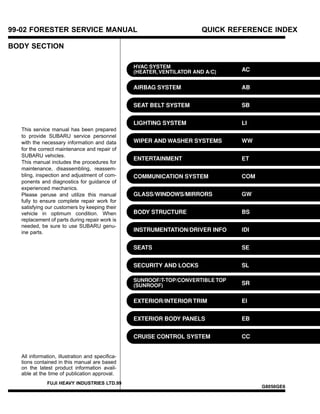
99-02 FORESTER SERVICE MANUAL QUICK REFERENCE INDEX
BODY SECTION
G8050GE6
2. HVAC SYSTEM (HEATER, VENTILATOR
AND A/C)
AC
Page
1. General Description.....................................................................................2
2. Refrigerant Pressure with Manifold Gauge Set ........................................18
3. Refrigerant Recovery Procedure...............................................................19
4. Refrigerant Charging Procedure ...............................................................20
5. Refrigerant Leak Check ............................................................................23
6. Compressor Oil .........................................................................................25
7. Heater Unit ................................................................................................26
8. Blower Motor Assembly.............................................................................27
9. Power Transistor (Heater Blower Resistor) ..............................................28
10. Heater Core...............................................................................................29
11. Control Unit ...............................................................................................30
12. Compressor...............................................................................................32
13. Condenser.................................................................................................34
14. Receiver Drier ...........................................................................................35
15. Intake Unit .................................................................................................36
16. Flexible Hose.............................................................................................38
17. Relay and Fuse.........................................................................................39
18. Pressure Switch (Dual Switch)..................................................................40
19. Air Vent Grille ............................................................................................41
20. Heater Duct ...............................................................................................42
21. Heater Vent Duct.......................................................................................43
22. General Diagnostics..................................................................................44
3. 1. General Description S701001
A: SPECIFICATIONS S701001E49
1. HEATER SYSTEM S701001E4901
Item Specifications Condition
Heating capacity
LHD model
5.1 kW (4,386 kcal/h, 17,404 BTU/h)
or more
쐌 Mode selector switch: HEAT
쐌 Temperature control switch: FULL HOT
쐌 Temperature difference between hot
water and inlet air: 65°C (149°F)
쐌 Hot water flow rate: 360 (95.1 US gal,
79.2 Imp gal)/h
RHD model
4.93 kW (4,240 kcal/h, 16,824 BTU/h)
or more
Air flow rate
LHD model 280 m3
(9,887 cu ft)/h
Heat mode (FRESH), FULL HOT at 12.5 V
RHD model 300 m3
(10,593 cu ft)/h
Max air flow rate
LHD model 480 m3
(16,949 cu ft)/h 쐌 Temperature control switch: FULL COLD
쐌 Blower fan speed: 4th position
쐌 Mode selector lever: RECIRC
RHD model 460 m3
(16,243 cu ft)/h
Heater core size
(height × length × width)
LHD model
193.5 × 152 × 35.0 mm
(7.62 × 5.98 × 1.378 in)
—
RHD model
161.4 × 176.4 × 32 mm
(6.35 × 6.94 × 1.26 in)
Blower
motor
Type
LHD model Magnet motor 260 W or less
at 12 V
RHD model Magnet motor 250 W or less
Fan type and size
(diameter × width)
LHD model
Sirocco fan type
150 × 75 mm (5.91 × 2.95 in)
—
RHD model
Sirocco fan type
150 × 75 mm (5.91 × 2.95 in)
AC-2
GENERAL DESCRIPTION
HVAC System (Heater, Ventilator and A/C)
4. 2. A/C SYSTEM S701001E4902
쐌 LHD Model:
Item Specifications
Type of air conditioner Reheat air-mix type
Cooling capacity
5.117 kW
(4,400 kcal/h, 17,459 BTU/h)
Refrigerant
HFC-134a (CH2FCF3)
[0.65±0.05 kg (1.43±0.11 lb)]
Compressor
Type 5-vane rotary, fix volume (KC50G)
Discharge 140 cm3
(8.54 cu in)/rev
Max. permissible speed 7,000 rpm
Magnet clutch
Type Dry, single-disc type
Power consumption 38 W
Type of belt V-Ribbed 4 PK
Pulley dia. (effective dia.) 125 mm (4.92 in)
Pulley ratio 1.064
Condenser
Type Corrugated fin (Multi-flow)
Core face area 0.255 m2
(2.74 sq ft)
Dimensions (W × H × T)
22 × 374 × 683 mm
(0.87 × 14.72 × 26.89 in)
Radiation area 6.52 m2
(70 sq ft)
Receiver drier Effective inner capacity 250 cm3
(15.26 cu in)
Expansion valve Type Internal equalizing
Evaporator
Type Single tank
Dimensions (W × H × T)
60 × 224 × 235 mm
(2.36 × 8.82 × 9.25 in)
Blower fan
Fan type Sirocco fan
Outer diameter × width 150 × 75 mm (5.91 × 2.95 in)
Power consumption 260 W at 12 V
Condenser fan (Sub fan)
Motor type Magnet
Power consumption 70 W at 12 V
Fan outer diameter 320 mm (12.60 in)
Radiator fan (Main fan)
Motor type Magnet
Power consumption 70 W at 12 V
Fan outer diameter 320 mm (12.60 in)
Dual switch
(Pressure switch)
Low-pressure switch
operating pressure
ON → OFF
177±25 kPa
(1.80±0.25 kg/cm2
, 25.6±3.6 psi)
OFF → ON
Less than 216 kPa
(2.2 kg/cm2
, 31 psi)
High-pressure switch
operating pressure
ON → OFF
2,940±200 kPa
(29.98±2.04 kg/cm2
, 426.3±29.0 psi)
DIFF
590±200 kPa
(6.02±2.04 kg/cm2
, 85.6±29.0 psi)
Compressor relief valve blow-out pressure
3,600±300 kPa
(36.71±3.06 kg/cm2
, 522.0±43.5 psi)
Thermo control amplifier working temperature
(Evaporator outlet air)
S4M0511A
AC-3
GENERAL DESCRIPTION
HVAC System (Heater, Ventilator and A/C)
5. 쐌 RHD Model:
Item Specifications
Type of air conditioner Reheat air-mix type
Cooling capacity 5.059 kW (4,350 kcal/h, 17,261 BTU/h)
Refrigerant
HFC-134a (CH2FCF3)
[0.65±0.05 kg (1.43±0.11 lb)]
Compressor
Type 5-vane rotary, fix volume (KC50G)
Discharge 140 cm3
(8.54 cu in)/rev
Max. permissible speed 7,000 rpm
Magnet clutch
Type Dry, single-disc type
Power consumption 38 W
Type of belt V-Ribbed 4 PK
Pulley dia. (effective dia.) 125 mm (4.92 in)
Pulley ratio 1.064
Condenser
Type Corrugated fin (Multi-flow)
Core face area 0.231 m2
(2.48 sq ft)
Dimensions (W × H × T)
20 × 331 × 698 × mm
(0.79 × 13.03 × 27.48 in)
Radiation area 7.2 m2
(77 sq ft)
Receiver drier Effective inner capacity 250 cm3
(15.26 cu in)
Expansion valve Type Internal equalizing
Evaporator
Type Single tank
Dimensions (W × H × T)
60 × 224 × 235 mm
(2.36 × 8.82 × 9.25 in)
Blower fan
Fan type Sirocco fan
Outer diameter × width 150 × 75 mm (5.91 × 2.95 in)
Power consumption 250 W at 12 V
Condenser fan (Sub fan)
Motor type Magnet
Power consumption 70 W at 12 V
Fan outer diameter 320 mm (12.60 in)
Radiator fan (Main fan)
Motor type Magnet
Power consumption 70 W at 12 V
Fan outer diameter 320 mm (12.60 in)
Dual switch
(Pressure switch)
Low-pressure switch
operating pressure
ON → OFF
177±25 kPa
(1.8±0.25 kg/cm2
, 26±3.6 psi)
OFF → ON
Less than 216 kPa
(2.2 kg/cm2
, 31 psi)
High-pressure switch
operating pressure
ON → OFF
2,650±200 kPa
(27.02±2.04 kg/cm2
, 384±29 psi)
OFF → ON
1,471±200 kPa
(15±2.04 kg/cm2
, 213±29 psi)
Compressor relief valve blow-out pressure
3,600±300 kPa
(36.71±3.06 kg/cm2
, 522.0±43.5 psi)
Thermo control amplifier working temperature
(Evaporator outlet air)
S4M0275A
AC-4
GENERAL DESCRIPTION
HVAC System (Heater, Ventilator and A/C)
6. B: COMPONENT S701001A05
1. HEATER UNIT S701001A0501
쐌 LHD Model:
H4M1045B
(1) Vent door
(2) DEF door
(3) DEF lever
(4) Heater core
(5) Heater case FRONT
(6) Mix door
(7) Mix lever
(8) Foot door
(9) Foot duct
(10) Heater case REAR
(11) Foot lever lower
(12) Foot lever upper
(13) Vent lever
(14) Side link
Tightening torque: N·m (kgf-m, ft-lb)
T: 7.35 (0.750, 5.421)
AC-5
GENERAL DESCRIPTION
HVAC System (Heater, Ventilator and A/C)
7. 쐌 RHD Model:
S4M0309A
(1) Heater case upper A
(2) Heater case upper B
(3) Vent door
(4) DEF door
(5) Sealing sponge
(6) DEF door lever
(7) DEF door link
(8) Vent door lever
(9) Side link
(10) Foot door
(11) Mix door
(12) Heater core
(13) Heater case lower
(14) Foot door lever
(15) Mix door lever
(16) Foot duct
Tightening torque: N·m (kg-m, ft-lb)
T: 7.35 (0.750, 5.421)
AC-6
GENERAL DESCRIPTION
HVAC System (Heater, Ventilator and A/C)
8. 2. INTAKE UNIT WITH EVAPORATOR S701001A0505
쐌 LHD Model:
S4M0501A
(1) Evaporator (With A/C model)
(2) Boot
(3) Block expansion valve (With A/C
model)
(4) Link
(5) Lever (A)
(6) Lever (B)
(7) Door (A)
(8) Door (B)
(9) Intake unit case inlet
(10) Thermistor (With A/C model)
(11) Intake unit case upper
(12) Intake unit case lower
(13) Drain hose
(14) Resistor
(15) Blower motor ASSY
(16) Aspirator pipe
(17) Cover
(18) Separator
(19) Rod
Tightening torque: N·m (kgf-m, ft-lb)
T: 7.35 (0.750, 5.421)
AC-7
GENERAL DESCRIPTION
HVAC System (Heater, Ventilator and A/C)
9. 쐌 RHD Model:
S4M0545A
(1) Door (A)
(2) Sealing sponge
(3) Door (B) lever
(4) Intake unit case upper
(5) Separator
(6) Cover
(7) Intake unit case lower
(8) Blower motor ASSY
(9) Door (B)
(10) Link
(11) Door (A) lever
(12) Evaporator (With A/C model)
(13) Thermo control amplifier (With
A/C model)
(14) Clamp
(15) Pipe (With A/C model)
(16) Expansion valve (With A/C
model)
(17) Drain hose
Tightening torque: N·m (kgf-m, ft-lb)
T: 7.35 (0.750, 5.421)
AC-8
GENERAL DESCRIPTION
HVAC System (Heater, Ventilator and A/C)
10. 3. CONTROL UNIT S701001A0503
S4M0083A
(1) Temperature control cable
(2) Recirc control cable
(3) Clip
(4) Blower switch ASSY
(5) Harness ASSY
(6) Bulb
(7) A/C switch ASSY
(8) Mode control cable
(9) Control dial knob
(10) A/C switch knob
(11) Control lever knob
(12) Plate
(13) Base unit
AC-9
GENERAL DESCRIPTION
HVAC System (Heater, Ventilator and A/C)
11. 4. AIR CONDITIONING UNIT S701001A0504
쐌 LHD Model:
S4M0486A
(1) Condenser
(2) Pipe (From condenser to
receiver drier)
(3) Receiver drier
(4) Pipe (From receiver drier to
intake unit)
(5) Hose (Low-pressure)
(6) Compressor
(7) Hose (High-pressure)
Tightening torque: N·m (kgf-m, ft-lb)
T1: 7.4 (0.75, 5.4)
T2: 15 (1.5, 10.8)
AC-10
GENERAL DESCRIPTION
HVAC System (Heater, Ventilator and A/C)
12. Thank you very much for
your reading. Please Click
Here. Then Get COMPLETE
MANUAL. NO WAITING
NOTE:
If there is no response to
click on the link above,
please download the PDF
document first and then
click on it.
15. C: CAUTION S701001A03
1. HFC-134a A/C SYSTEM S701001A0301
쐌 Unlike the old conventional HFC-12 system
components, the cooling system components for
the HFC-134a system such as the refrigerant and
compressor oil are incompatible.
쐌 Vehicles with the HFC-134a system can be
identified by the label “A” attached to the vehicle.
Before maintenance, check which A/C system is
installed in the vehicle.
S4M0547A
2. COMPRESSOR OIL S701001A0302
쐌 HFC-134a compressor oil has no compatibility
with that for R12 system.
쐌 Use only the manufacturer-authorized compres-
sor oil for the HFC-134a system; only use
ZXL200PG.
쐌 Do not mix multiple compressor oils.
If HFC-12 compressor oil is used in a HFC-134a
A/C system, the compressor may become stuck
due to poor lubrication, or the refrigerant may leak
due to swelling of rubber parts.
On the other hand, if HFC-134a compressor oil is
used in a HFC-12 A/C system, the durability of the
A/C system will be lowered.
쐌 HFC-134a compressor oil is very hygroscopic.
When replacing or installing/removing A/C parts,
immediately isolate the oil from the atmosphere
using a plug or tape. In order to avoid moisture,
store the oil in a container with its cap tightly
closed.
3. REFRIGERANT S701001A0303
쐌 The HFC-12 refrigerant cannot be used in the
HFC-134a A/C system. The HFC-134a refrigerant,
also, cannot be used in the HFC-12 A/C system.
쐌 If an incorrect or no refrigerant is used, poor
lubrication will result and the compressor itself may
be damaged.
4. HANDLING OF REFRIGERANT S701001A0304
쐌 The refrigerant boils at approx. −30°C (−22°F).
When handling it, be sure to wear safety goggles
and protective gloves. Direct contact of the refrig-
erant with skin may cause frostbite.
If the refrigerant gets into your eye, avoid rubbing
your eyes with your hands. Wash your eye with
plenty of water, and receive medical treatment
from an eye doctor.
쐌 Do not heat a service can. If a service can is
directly heated, or put into boiling water, the inside
pressure will become extremely high. This may
cause the can to explode. If a service can must be
warmed up, use hot water in 40°C (104°F) max.
쐌 Do not drop or impact a service can. (Observe
the precautions and operation procedure
described on the refrigerant can.)
쐌 When the engine is running, do not open the
high-pressure valve of the manifold gauge. The
high-pressure gas will back-flow resulting in an
explosion of the can.
쐌 The refrigerant is non-toxic and harmless under
normal operating circumstance, but it may change
to phosgene (a noxious fume) under open flames
or high temperatures (caused by a cigarette or
heater).
쐌 Provide good ventilation and do not work in a
closed area.
쐌 Never perform a gas leak test using a halide
torch-type leak tester.
쐌 In order to avoid destroying the ozone layer, pre-
vent HFC-134a from being released into the atmo-
sphere. Using a refrigerant recovery system, dis-
charge and reuse it.
G4M0979
AC-13
GENERAL DESCRIPTION
HVAC System (Heater, Ventilator and A/C)
16. 5. O-RING CONNECTIONS S701001A0305
쐌 Use new O-rings.
쐌 In order to keep the O-rings free of lint which will
cause a refrigerant gas leak, perform operations
without gloves and shop towels.
쐌 Apply the compressor oil to the O-rings to avoid
sticking, then install them.
쐌 Use a torque wrench to tighten the O-ring fit-
tings: Over-tightening will damage the O-ring and
tube end distortion.
쐌 If the operation is interrupted before completing
a pipe connection, recap the tubes, components,
and fittings with a plug or tape to prevent contami-
nation from entering.
G4M0581
쐌 Visually check the surfaces and mating surfaces
of O-rings, threads, and connecting points. If a fail-
ure is found, replace the applicable parts.
쐌 Install the O-rings at right angle to the tube
beards.
G4M0582
쐌 Use the oil specified in the service manual to
lubricate the O-rings.
Apply the oil to the top and sides of the O-rings
before installation.
Apply the oil to the area including the O-rings and
tube beads.
G4M0583
쐌 When connecting hoses or pipes, use 2
wrenches (a torque wrench for tightening). While
securing one side with a wrench, tighten the other
side to the specified torque with a torque wrench.
If only one wrench is used to tighten, the tighten-
ing torque will be excessive or insufficient. This
may cause a pipe distortion or gas leak, resulting
in damage to hoses and pipes.
쐌 After tightening, using a clean shop towel to
remove excess oil from the connections and any oil
which may have run on the vehicle body or other
parts.
쐌 If any leakage is suspected after tightening, do
not retighten the connections, Disconnect the
connections, remove the O-rings, and check the
O-rings, threads, and connections.
G4M0584
AC-14
GENERAL DESCRIPTION
HVAC System (Heater, Ventilator and A/C)
17. D: PREPARATION TOOL S701001A17
CAUTION:
When working on vehicles with the HFC-134a
system, only use HFC-134a specified tools and
parts. Do not mix with CFC-12 tools and parts.
If HFC-134a and CFC-12 refrigerant or com-
pressor oil is mixed, poor lubrication will result
and the compressor itself may be destroyed.
In order to help prevent mixing HFC-134a and
CFC-12 parts and liquid, the tool and screw
type and the type of service valves used are
different. The gas leak detectors for the HFC-
134a and CFC-12 systems must also not be
interchanged.
HFC-134a CFC-12
Tool screw type Millimeter size Inch size
Valve type Quick joint type Screw-in type
Tools and Equipment Description
Wrench
G4M0571
Various WRENCHES will be required to service any A/C system. A 7
to 40 N·m (0.7 to 4.1 kg-m, 5 to 30 ft-lb) torque wrench with various
crowfoot wrenches will be needed. Open end or flare nut wrenches
will be needed for back-up on the tube and hose fittings.
Applicator bottle
G4M0572
A small APPLICATOR BOTTLE is recommended to apply refrigerant
oil to the various parts. They can be obtained at a hardware or drug
store.
Manifold gauge set
G4M0573
A MANIFOLD GAUGE SET (with hoses) can be obtained from either
a commercial refrigeration supply house or from an auto shop equip-
ment supplier.
AC-15
GENERAL DESCRIPTION
HVAC System (Heater, Ventilator and A/C)
18. Tools and Equipment Description
Refrigerant recovery system
G4M0574
A REFRIGERANT RECOVERY SYSTEM is used for the recovery
and reuse of A/C system refrigerant after contaminants and moisture
have been removed from the refrigerant.
Syringe
G4M0575
A graduated plastic SYRINGE will be needed to add oil back into the
system. The syringe can be found at a pharmacy or drug store.
Vacuum pump
G4M0576
A VACUUM PUMP (in good working condition) is necessary, and may
be obtained from either a commercial refrigeration supply house or an
automotive equipment supplier.
Can tap
G4M0577
A CAN TAP for the 397 g (14 oz) can is available from an auto sup-
ply store.
AC-16
GENERAL DESCRIPTION
HVAC System (Heater, Ventilator and A/C)
19. Tools and Equipment Description
Thermometer
G4M0578
Pocket THERMOMETERS are available from either industrial hard-
ware store or commercial refrigeration supply houses.
Electronic leak detector
G4M0579
An ELECTRONIC LEAK DETECTOR can be obtained from either a
specialty tool supply or an A/C equipment supplier.
Weight scale
G4M0580
A WEIGHT SCALE such as an electronic charging scale or a bath-
room scale with digital display will be needed if a 13.6 kg (30 lb)
refrigerant container is used.
AC-17
GENERAL DESCRIPTION
HVAC System (Heater, Ventilator and A/C)