1. Title: STRUCTURAL DESIGN REPORT FOR ELEVATOR SLAB:-
Client: JOHN HOPKINS ARAMCO HEALTH CARE, DAHRAN
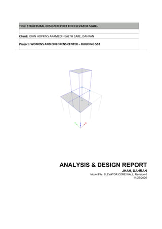
Project: WOMENS AND CHILDRENS CENTER – BUILDING 552
ANALYSIS & DESIGN REPORT
JHAH, DAHRAN
Model File: ELEVATOR CORE WALL, Revision 0
11/29/2020
2. Issued by:
ENGR. GOVIND SHRIRAM CHHAWSARIA Electronic Signature
DESIGN by:
ENGR. AMIT JITENDRA CHHAWSARIA Electronic Signature
Reviewed by:
ENGR. GOVIND SHRIRAM CHHAWSARIA Electronic Signature
Approved by:
ENGR. GOVIND SHRIRAM CHHAWSARIA Electronic Signature
Revision control sheet
Revision Date
Purposee
Reason
for
revision
Issued by
Checkedby
Reviewed
by Approvedby
00 2020/11/18 Concept 00 GSC GSC GSC
3. Preliminary or pending information
Edition Sections Concepts Status
Document status:
☐ For approval
☒For information
Critical:
☐ Yes
☒NO
4.
5. Table of Contents
1. Structure Data 5
1.1 Story Data 5
1.2 Grid Data 5
1.3 Point Coordinates 5
1.4 Line Connectivity 5
1.5 Area Connectivity 6
1.6 Mass 6
1.7 Groups 7
2. Properties 8
2.1 Materials 8
2.2 Frame Sections 8
2.3 Reinforcement Sizes 15
3. Assignments 17
3.1 Joint Assignments 17
3.2 Frame Assignments 17
4. Loads 19
4.1 Load Patterns 19
4.2 Load Sets 19
4.3 Applied Loads 19
4.3.1 Line Loads 19
4.4 Load Combinations 21
5. Analysis Results 23
5.1 Structure Results 23
5.2 Story Results 24
5.3 Point Results 26
6. Design Data 30
6.1 Concrete Frame Design 30
6. List of Tables
Table 1.1 Story Definitions 5
Table 1.2 Grid Definitions - General 5
Table 1.3 Grid Definitions - Grid Lines 5
Table 1.4 Point Bays 5
Table 1.5 Column Bays 5
Table 1.6 Beam Bays 6
Table 1.7 Floor Bays 6
Table 1.8 Mass Source Definition 6
Table 1.9 Centers Of Mass And Rigidity 6
Table 1.10 Mass Summary by Diaphragm 7
Table 1.11 Mass Summary by Story 7
Table 1.12 Mass Summary by Group 7
Table 1.13 Group Definitions 7
Table 2.1 Material Properties - General 8
Table 2.2 Frame Section Property Definitions - Summary 8
Table 2.3 Reinforcing Bar Sizes 15
Table 3.1 Joint Assignments - Summary 17
Table 3.2 Frame Assignments - Summary 17
Table 4.1 Load Pattern Definitions 19
Table 4.2 Shell Uniform Load Sets 19
Table 4.3 Frame Loads Assignments - Distributed 19
Table 4.4 Load Combination Definitions 21
Table 5.1 Base Reactions 23
Table 5.2 Centers Of Mass And Rigidity 23
Table 5.3 Diaphragm Center Of Mass Displacements 23
Table 5.4 Story Max Over Avg Displacements 24
Table 5.5 Story Drifts 24
Table 5.6 Story Forces 25
Table 5.7 Joint Reactions 26
Table 6.1 Concrete Frame Design Preferences - ACI 318-14 30
Table 6.2 Concrete Column PMM Envelope - ACI 318-14 30
Table 6.3 Concrete Column Shear Envelope - ACI 318-14 30
Table 6.4 Concrete Beam Flexure Envelope - ACI 318-14 31
Table 6.5 Concrete Beam Shear Envelope - ACI 318-14 32
Table 6.6 Concrete Joint Envelope - ACI 318-14 34
Table 6.7 Concrete Column Design Summary - ACI 318-14 34
Table 6.8 Concrete Beam Design Summary - ACI 318-14 36
Table 6.9 Concrete Joint Design Summary - ACI 318-14 41
7. Structure Data 11/29/2020
Page 9 of 47
1 Structure Data
This chapter provides model geometry information, including items such as story levels, point coordinates, and
element connectivity.
1.1 Story Data
Table 1.1 - Story Definitions
Tower Name
Height
m
Master
Story
Similar To
Splice
Story
Color
T1 Story2 3 Yes None No Cyan
T1 Story1 3 No Story2 No Red
1.2 Grid Data
Table 1.2 - Grid Definitions - General
Tower Name Type
Ux
m
Uy
m
Rz
deg
Story
Range
Bubble
Size
mm
Color
T1 G1 Cartesian 0 0 0 Default 1250 Gray6
Table 1.3 - Grid Definitions - Grid Lines
Name Grid Line Type
Ordinate
m
Bubble
Location
Visible
G1 X (Cartesian) 0 End Yes
G1 X (Cartesian) 1.9 End Yes
G1 X (Cartesian) 4.2 End Yes
G1 Y (Cartesian) 0 Start Yes
G1 Y (Cartesian) 2.125 Start Yes
G1 Y (Cartesian) 3.9 Start Yes
1.3 Point Coordinates
Table 1.4 - Point Bays
Label
Is Auto
Point
X
m
Y
m
DZBelow
m
1 No 1.9 3.9 0
2 No 4.2 3.9 0
3 No 1.9 2.125 0
4 No 4.2 2.125 0
5 No 0 3.9 0
6 No 0 2.125 0
7 No 0 0 0
8 No 1.9 0 0
9 Yes 3.165 3.1013 0
10 Yes 1.3749 2.5425 0
1.4 Line Connectivity
Table 1.5 - Column Bays
Label PointBayI PointBayJ IEndStory
C1 1 1 Below
C2 3 3 Below
C3 2 2 Below
C4 4 4 Below
8. Structure Data 11/29/2020
Page 10 of 47
Table 1.6 - Beam Bays
Label PointBayI PointBayJ
B1 5 1
B2 6 3
B3 6 5
B4 7 6
B5 3 1
B6 8 3
B7 7 8
B8 3 4
B9 1 2
B10 4 2
1.5 Area Connectivity
Table 1.7 - Floor Bays
Label NumPoints PointNumber PointBay
F1 4 1 5
F1 2 1
F1 3 3
F1 4 6
F2 4 1 6
F2 2 3
F2 3 8
F2 4 7
F3 4 1 1
F3 2 2
F3 3 4
F3 4 3
1.6 Mass
Table 1.8 - Mass Source Definition
Name Is Default
Include
Lateral
Mass?
Include
Vertical
Mass?
Lump
Mass?
Source
Self
Mass?
Source
Added
Mass?
Source Load
Patterns?
Move Mass
Centroid?
Move
Ratio X
Move
Ratio Y
MsSrc1 Yes Yes No Yes Yes Yes No Yes 0.05 0.05
Table 1.9 - Centers Of Mass And Rigidity
Story Diaphragm
Mass X
kg
Mass Y
kg
XCM
m
YCM
m
Cum
Mass X
kg
Cum
Mass Y
kg
XCCM
m
YCCM
m
XCR
m
YCR
m
Story2 D1 3087.66 3087.66 3.165 3.1013 3087.66 3087.66 3.165 3.1013
Story1 D1 5338.08 5338.08 1.3749 2.5425 8425.74 8425.74 2.0309 2.7473
Table 1.10 - Mass Summary by Diaphragm
Story Diaphragm
Mass X
kg
Mass Y
kg
Mass
Moment of
Inertia
ton-m2
X Mass
Center
m
Y Mass
Center
m
Story2 D1 3087.66 3087.66 6.5153 3.165 3.1013
Story1 D1 5338.08 5338.08 14.4847 1.3749 2.5425
9. Structure Data 11/29/2020
Page 11 of 47
Table 1.11 - Mass Summary by Story
Story
UX
kg
UY
kg
UZ
kg
Story2 3087.66 3087.66 0
Story1 7659.76 7659.76 0
Base 1441.66 1441.66 0
Table 1.12 - Mass Summary by Group
Group
Self Mass
kg
Self
Weight
kN
Mass X
kg
Mass Y
kg
Mass Z
kg
All 12189.08 0 12189.08 12189.08 0
1.7 Groups
Table 1.13 - Group Definitions
Name Color
Steel
Design?
Concrete
Design?
Composite
Design?
All Yellow No No No
17. Assignments 11/29/2020
Page 19 of 47
3 Assignments
This chapter provides a listing of the assignments applied to the model.
3.1 Joint Assignments
Table 3.1 - Joint Assignments - Summary
Story Label UniqueName Diaphragm Restraints
Story2 1 9 From Area
Story2 2 11 From Area
Story2 3 10 From Area
Story2 4 12 From Area
Story2 9 17 D1
Story1 1 1 From Area UZ; RZ
Story1 2 2 From Area UZ; RZ
Story1 3 5 From Area UZ; RZ
Story1 4 6 From Area UZ; RZ
Story1 5 13 From Area
Story1 6 14 From Area
Story1 7 15 From Area
Story1 8 16 From Area
Story1 10 18 D1
Base 1 3 From Area UX; UY; UZ; RX; RY; RZ
Base 2 7 From Area UX; UY; UZ; RX; RY; RZ
Base 3 4 From Area UX; UY; UZ; RX; RY; RZ
Base 4 8 From Area UX; UY; UZ; RX; RY; RZ
3.2 Frame Assignments
Table 3.2 - Frame Assignments - Summary
Story Label UniqueName
Design
Type
Length
m
Analysis
Section
Design
Section
Max
Station
Spacing
m
Min
Number
Stations
Releases
Story2 B5 23 Beam 1.775 B250X400 B250X400 0.5
Story2 B8 19 Beam 2.3 B250X400 B250X400 0.5
Story2 B9 18 Beam 2.3 B250X400 B250X400 0.5
Story2 B10 21 Beam 1.775 B250X400 B250X400 0.5
Story2 C1 14 Column 3 C250X400 C250X400 3
Story2 C2 15 Column 3 C250X400 C250X400 3
Story2 C3 16 Column 3 C250X400 C250X400 3
Story2 C4 17 Column 3 C250X400 C250X400 3
Story1 B1 1 Beam 1.9 B250X450 B250X450 0.5 Yes
Story1 B2 2 Beam 1.9 B250X450 B250X450 0.5 Yes
Story1 B3 3 Beam 1.775 B250X450 B250X450 0.5 Yes
Story1 B4 4 Beam 2.125 B250X450 B250X450 0.5 Yes
Story1 B5 5 Beam 1.775 B250X450 B250X450 0.5 Yes
Story1 B6 6 Beam 2.125 B250X450 B250X450 0.5 Yes
Story1 B7 7 Beam 1.9 B250X400 B250X400 0.5 Yes
Story1 B8 8 Beam 2.3 B250X450 B250X450 0.5
Story1 B9 9 Beam 2.3 B250X450 B250X450 0.5
Story1 B10 20 Beam 1.775 B250X400 B250X400 0.5
Story1 C1 10 Column 3 C250X400 C250X400 3
Story1 C2 11 Column 3 C250X400 C250X400 3
Story1 C3 12 Column 3 C250X400 C250X400 3
Story1 C4 13 Column 3 C250X400 C250X400 3
18. Loads 11/29/2020
Page 20 of 47
4 Loads
This chapter provides loading information as applied to the model.
4.1 Load Patterns
Table 4.1 - Load Pattern Definitions
Name
Is Auto
Load
Type
Self Weight
Multiplier
~LLRF Yes Other 0
Dead Slab No Dead 0
Equip Load No Live 0
FF No Dead 0
Live No Live 0
Self weight No Dead 1
4.2 Load Sets
Table 4.2 - Shell Uniform Load Sets
Name
Load
Pattern
Load
Value
kN/m2
FF Self weight 1.5
ULoadSet1
ULoadSet2
4.3 Applied Loads
4.3.1 Line Loads
Table 4.3 - Frame Loads Assignments - Distributed (Part 1 of 2)
Story Label UniqueName
Load
Pattern
Load
Type
Direction
Distance
Type
Relative
Distance
A
Relative
Distance
B
Absolute
Distance A
m
Absolute
Distance B
m
Story2 B5 23 Live Force Gravity Relative 0 1 0 1.775
Story2 B8 19 Live Force Gravity Relative 0 1 0 2.3
Story2 B9 18 Live Force Gravity Relative 0 1 0 2.3
Story2 B10 21 Live Force Gravity Relative 0 1 0 1.775
Story1 B1 1 Live Force Gravity Relative 0 1 0 1.9
Story1 B2 2 Live Force Gravity Relative 0 1 0 1.9
Story1 B3 3 Live Force Gravity Relative 0 1 0 1.775
Story1 B4 4 Live Force Gravity Relative 0 1 0 2.125
Story1 B5 5 Live Force Gravity Relative 0 1 0 1.775
Story1 B6 6 Live Force Gravity Relative 0 1 0 2.125
Story1 B7 7 Live Force Gravity Relative 0 1 0 1.9
Story1 B8 8 Live Force Gravity Relative 0 1 0 2.3
Story1 B9 9 Live Force Gravity Relative 0 1 0 2.3
Story1 B10 20 Live Force Gravity Relative 0 1 0 1.775
Story2 B5 23 FF Force Gravity Relative 0 1 0 1.775
Story2 B8 19 FF Force Gravity Relative 0 1 0 2.3
Story2 B9 18 FF Force Gravity Relative 0 1 0 2.3
Story2 B10 21 FF Force Gravity Relative 0 1 0 1.775
Story1 B1 1 FF Force Gravity Relative 0 1 0 1.9
Story1 B2 2 FF Force Gravity Relative 0 1 0 1.9
Story1 B3 3 FF Force Gravity Relative 0 1 0 1.775
Story1 B4 4 FF Force Gravity Relative 0 1 0 2.125
Story1 B5 5 FF Force Gravity Relative 0 1 0 1.775
19. Loads 11/29/2020
Page 21 of 47
Story Label UniqueName
Load
Pattern
Load
Type
Direction
Distance
Type
Relative
Distance
A
Relative
Distance
B
Absolute
Distance A
m
Absolute
Distance B
m
Story1 B6 6 FF Force Gravity Relative 0 1 0 2.125
Story1 B7 7 FF Force Gravity Relative 0 1 0 1.9
Story1 B8 8 FF Force Gravity Relative 0 1 0 2.3
Story1 B9 9 FF Force Gravity Relative 0 1 0 2.3
Story1 B10 20 FF Force Gravity Relative 0 1 0 1.775
Story2 B5 23 Dead Slab Force Gravity Relative 0 1 0 1.775
Story2 B8 19 Dead Slab Force Gravity Relative 0 1 0 2.3
Story2 B9 18 Dead Slab Force Gravity Relative 0 1 0 2.3
Story2 B10 21 Dead Slab Force Gravity Relative 0 1 0 1.775
Story1 B1 1 Dead Slab Force Gravity Relative 0 1 0 1.9
Story1 B2 2 Dead Slab Force Gravity Relative 0 1 0 1.9
Story1 B3 3 Dead Slab Force Gravity Relative 0 1 0 1.775
Story1 B4 4 Dead Slab Force Gravity Relative 0 1 0 2.125
Story1 B5 5 Dead Slab Force Gravity Relative 0 1 0 1.775
Story1 B6 6 Dead Slab Force Gravity Relative 0 1 0 2.125
Story1 B7 7 Dead Slab Force Gravity Relative 0 1 0 1.9
Story1 B8 8 Dead Slab Force Gravity Relative 0 1 0 2.3
Story1 B9 9 Dead Slab Force Gravity Relative 0 1 0 2.3
Story1 B10 20 Dead Slab Force Gravity Relative 0 1 0 1.775
Table 4.3 - Frame Loads Assignments - Distributed (Part 2 of 2)
Force A
kN/m
Force B
kN/m
7.3 7.3
7.3 7.3
7.3 7.3
7.3 7.3
3.5 3.5
3.5 3.5
3.5 3.5
3.5 3.5
3.5 3.5
3.5 3.5
3.5 3.5
3.5 3.5
3.5 3.5
3.5 3.5
1.1 1.1
1.1 1.1
1.1 1.1
1.1 1.1
1.1 1.1
1.1 1.1
1.1 1.1
1.1 1.1
1.1 1.1
1.1 1.1
1.1 1.1
1.1 1.1
1.1 1.1
1.1 1.1
2.1 2.1
20. Loads 11/29/2020
Page 22 of 47
Force A
kN/m
Force B
kN/m
2.1 2.1
2.1 2.1
2.1 2.1
2.1 2.1
2.1 2.1
2.1 2.1
2.1 2.1
2.1 2.1
2.1 2.1
2.1 2.1
2.1 2.1
2.1 2.1
2.1 2.1
4.4 Load Combinations
Table 4.4 - Load Combination Definitions
Name Type Is Auto Load Name SF Notes
DComsl1 Linear Add No Dead 1
DComsl1 Dead 1
DCon1 Linear Add Yes FF 1.4 Dead [Strength]
DCon1 Dead 1.4
DCon1 Dead Slab 1.4
DCon1 elf Weight 1.4
DCon2 Linear Add Yes Live 1.6 Dead + Live [Strength]
DCon2 FF 1.2
DCon2 Equip Load 1.6
DCon2 Dead 1.2
DCon2 Dead Slab 1.2
DCon2 elf Weight 1.2
DWal1 Linear Add Yes FF 1.4 Dead [Strength]
DWal1 Dead 1.4
DWal1 Dead Slab 1.4
DWal1 elf Weight 1.4
DWal2 Linear Add Yes Live 1.6 Dead + Live [Strength]
DWal2 FF 1.2
DWal2 Equip Load 1.6
DWal2 Dead 1.2
DWal2 Dead Slab 1.2
DWal2 elf Weight 1.2
21. Analysis Results 11/29/2020
Page 23 of 47
5 Analysis Results
This chapter provides analysis results.
5.1 Structure Results
Table 5.1 - Base Reactions
Output
Case
Case Type
FX
kN
FY
kN
FZ
kN
MX
kN-m
MY
kN-m
MZ
kN-m
X
m
Y
m
Z
m
Live LinStatic 0 0 129.0575 339.7463 -301.5448 -3.2347 0 0 0
FF LinStatic 0 0 119.534 324.9533 -297.1996 -2.3423 0 0 0
Equip Load LinStatic 0 0 0 0 0 0 0 0 0
Dead LinStatic 0 0 119.534 324.9533 -297.1996 -2.3423 0 0 0
Dead Slab LinStatic 0 0 58.8525 147.8695 -124.2518 -1.9408 0 0 0
elf Weight LinStatic 0 0 0 0 0 0 0 0 0
DComsl1 Combination 0 0 239.068 649.9065 -594.3992 -4.6846 0 0 0
DCon1 Combination 0 0 417.0887 1116.8865 -1006.1114 -9.2755 0 0 0
DCon2 Combination 0 0 563.9966 1500.9254 -1344.8528 -13.1259 0 0 0
DWal1 Combination 0 0 417.0887 1116.8865 -1006.1114 -9.2755 0 0 0
DWal2 Combination 0 0 563.9966 1500.9254 -1344.8528 -13.1259 0 0 0
Table 5.2 - Centers Of Mass And Rigidity
Story Diaphragm
Mass X
kg
Mass Y
kg
XCM
m
YCM
m
Cum
Mass X
kg
Cum
Mass Y
kg
XCCM
m
YCCM
m
XCR
m
YCR
m
Story2 D1 3087.66 3087.66 3.165 3.1013 3087.66 3087.66 3.165 3.1013
Story1 D1 5338.08 5338.08 1.3749 2.5425 8425.74 8425.74 2.0309 2.7473
Table 5.3 - Diaphragm Center Of Mass Displacements
Story Diaphragm
Output
Case
Case Type
UX
mm
UY
mm
RZ
rad
Point
X
m
Y
m
Z
m
Story2 D1 Live LinStatic -0.37 -0.126 -9.9E-05 17 3.165 3.1013 6
Story2 D1 FF LinStatic -0.275 -0.091 -7.2E-05 17 3.165 3.1013 6
Story2 D1 Equip Load LinStatic 0 0 0 17 3.165 3.1013 6
Story2 D1 Dead LinStatic -0.275 -0.091 -7.2E-05 17 3.165 3.1013 6
Story2 D1 Dead Slab LinStatic -0.222 -0.076 -5.9E-05 17 3.165 3.1013 6
Story2 D1 elf Weight LinStatic 0 0 0 17 3.165 3.1013 6
Story2 D1 DComsl1 Combination -0.55 -0.181 -0.000143 17 3.165 3.1013 6
Story2 D1 DCon1 Combination -1.08 -0.36 -0.000284 17 3.165 3.1013 6
Story2 D1 DCon2 Combination -1.518 -0.511 -0.000401 17 3.165 3.1013 6
Story2 D1 DWal1 Combination -1.08 -0.36 -0.000284 17 3.165 3.1013 6
Story2 D1 DWal2 Combination -1.518 -0.511 -0.000401 17 3.165 3.1013 6
Story1 D1 Live LinStatic -0.179 -0.042 0 18 1.3749 2.5425 3
Story1 D1 FF LinStatic -0.133 -0.03 0 18 1.3749 2.5425 3
Story1 D1 Equip Load LinStatic 0 0 0 18 1.3749 2.5425 3
Story1 D1 Dead LinStatic -0.133 -0.03 0 18 1.3749 2.5425 3
Story1 D1 Dead Slab LinStatic -0.107 -0.025 0 18 1.3749 2.5425 3
Story1 D1 elf Weight LinStatic 0 0 0 18 1.3749 2.5425 3
Story1 D1 DComsl1 Combination -0.265 -0.06 0 18 1.3749 2.5425 3
Story1 D1 DCon1 Combination -0.521 -0.119 0 18 1.3749 2.5425 3
Story1 D1 DCon2 Combination -0.733 -0.169 0 18 1.3749 2.5425 3
Story1 D1 DWal1 Combination -0.521 -0.119 0 18 1.3749 2.5425 3
Story1 D1 DWal2 Combination -0.733 -0.169 0 18 1.3749 2.5425 3
22. Analysis Results 11/29/2020
Page 24 of 47
5.2 Story Results
Table 5.4 - Story Max Over Avg Displacements
Story
Output
Case
Case Type Direction
Maximum
mm
Average
mm
Ratio
Story2 Live LinStatic X 0.466 0.379 1.232
Story2 Live LinStatic Y 0.229 0.115 1.988
Story1 Live LinStatic X 0.179 0.179 1
Story1 Live LinStatic Y 0.042 0.042 1
Story2 FF LinStatic X 0.345 0.281 1.226
Story2 FF LinStatic Y 0.165 0.082 1.999
Story1 FF LinStatic X 0.133 0.133 1
Story1 FF LinStatic Y 0.03 0.03 1
Story2 Dead LinStatic X 0.345 0.281 1.226
Story2 Dead LinStatic Y 0.165 0.082 1.999
Story1 Dead LinStatic X 0.133 0.133 1
Story1 Dead LinStatic Y 0.03 0.03 1
Story2 Dead Slab LinStatic X 0.28 0.227 1.232
Story2 Dead Slab LinStatic Y 0.137 0.069 1.988
Story1 Dead Slab LinStatic X 0.107 0.107 1
Story1 Dead Slab LinStatic Y 0.025 0.025 1
Story2 DComsl1 Combination X 0.69 0.563 1.226
Story2 DComsl1 Combination Y 0.33 0.165 1.999
Story1 DComsl1 Combination X 0.265 0.265 1
Story1 DComsl1 Combination Y 0.06 0.06 1
Story2 DCon1 Combination X 1.357 1.106 1.228
Story2 DCon1 Combination Y 0.654 0.328 1.996
Story1 DCon1 Combination X 0.521 0.521 1
Story1 DCon1 Combination Y 0.119 0.119 1
Story2 DCon2 Combination X 1.909 1.553 1.229
Story2 DCon2 Combination Y 0.927 0.465 1.992
Story1 DCon2 Combination X 0.733 0.733 1
Story1 DCon2 Combination Y 0.169 0.169 1
Story2 DWal1 Combination X 1.357 1.106 1.228
Story2 DWal1 Combination Y 0.654 0.328 1.996
Story1 DWal1 Combination X 0.521 0.521 1
Story1 DWal1 Combination Y 0.119 0.119 1
Story2 DWal2 Combination X 1.909 1.553 1.229
Story2 DWal2 Combination Y 0.927 0.465 1.992
Story1 DWal2 Combination X 0.733 0.733 1
Story1 DWal2 Combination Y 0.169 0.169 1
Table 5.5 - Story Drifts
Story
Output
Case
Case Type Direction Drift Label
X
m
Y
m
Z
m
Story2 Live LinStatic X 9.6E-05 4 4.2 2.125 6
Story2 Live LinStatic Y 5.3E-05 2 4.2 3.9 6
Story2 FF LinStatic X 7.1E-05 4 4.2 2.125 6
Story2 FF LinStatic Y 3.8E-05 2 4.2 3.9 6
Story2 Dead LinStatic X 7.1E-05 4 4.2 2.125 6
Story2 Dead LinStatic Y 3.8E-05 2 4.2 3.9 6
Story2 Dead Slab LinStatic X 5.8E-05 4 4.2 2.125 6
Story2 Dead Slab LinStatic Y 3.2E-05 2 4.2 3.9 6
Story2 DComsl1 Combination X 0.000142 4 4.2 2.125 6
Story2 DComsl1 Combination Y 7.6E-05 2 4.2 3.9 6
Story2 DCon1 Combination X 0.000279 4 4.2 2.125 6
Story2 DCon1 Combination Y 0.000151 2 4.2 3.9 6
Story2 DCon2 Combination X 0.000393 4 4.2 2.125 6
23. Analysis Results 11/29/2020
Page 25 of 47
Story
Output
Case
Case Type Direction Drift Label
X
m
Y
m
Z
m
Story2 DCon2 Combination Y 0.000214 2 4.2 3.9 6
Story2 DWal1 Combination X 0.000279 4 4.2 2.125 6
Story2 DWal1 Combination Y 0.000151 2 4.2 3.9 6
Story2 DWal2 Combination X 0.000393 4 4.2 2.125 6
Story2 DWal2 Combination Y 0.000214 2 4.2 3.9 6
Story1 Live LinStatic X 6E-05 3 1.9 2.125 3
Story1 Live LinStatic Y 2.4E-05 4 4.2 2.125 3
Story1 FF LinStatic X 4.4E-05 3 1.9 2.125 3
Story1 FF LinStatic Y 1.7E-05 4 4.2 2.125 3
Story1 Dead LinStatic X 4.4E-05 3 1.9 2.125 3
Story1 Dead LinStatic Y 1.7E-05 4 4.2 2.125 3
Story1 Dead Slab LinStatic X 3.6E-05 3 1.9 2.125 3
Story1 Dead Slab LinStatic Y 1.4E-05 4 4.2 2.125 3
Story1 DComsl1 Combination X 8.8E-05 3 1.9 2.125 3
Story1 DComsl1 Combination Y 3.4E-05 4 4.2 2.125 3
Story1 DCon1 Combination X 0.000174 3 1.9 2.125 3
Story1 DCon1 Combination Y 6.7E-05 4 4.2 2.125 3
Story1 DCon2 Combination X 0.000244 3 1.9 2.125 3
Story1 DCon2 Combination Y 9.5E-05 4 4.2 2.125 3
Story1 DWal1 Combination X 0.000174 3 1.9 2.125 3
Story1 DWal1 Combination Y 6.7E-05 4 4.2 2.125 3
Story1 DWal2 Combination X 0.000244 3 1.9 2.125 3
Story1 DWal2 Combination Y 9.5E-05 4 4.2 2.125 3
Table 5.6 - Story Forces
Story Output Case Case Type Location
P
kN
VX
kN
VY
kN
T
kN-m
MX
kN-m
MY
kN-m
Story2 Live LinStatic Top 59.495 0 0 0 179.2287 -181.4598
Story2 Live LinStatic Bottom 59.495 0 0 0 179.2287 -181.4598
Story2 FF LinStatic Top 16.1417 0 0 0 48.6269 -49.2322
Story2 FF LinStatic Bottom 44.4174 0 0 0 133.8076 -135.4732
Story2 Equip Load LinStatic Top 0 0 0 0 0 0
Story2 Equip Load LinStatic Bottom 0 0 0 0 0 0
Story2 Dead LinStatic Top 16.1417 0 0 0 48.6269 -49.2322
Story2 Dead LinStatic Bottom 44.4174 0 0 0 133.8076 -135.4732
Story2 Dead Slab LinStatic Top 17.115 0 0 0 51.5589 -52.2008
Story2 Dead Slab LinStatic Bottom 17.115 0 0 0 51.5589 -52.2008
Story2 elf Weight LinStatic Top 0 0 0 0 0 0
Story2 elf Weight LinStatic Bottom 0 0 0 0 0 0
Story2 DComsl1 Combination Top 32.2834 0 0 0 97.2537 -98.4644
Story2 DComsl1 Combination Bottom 88.8349 0 0 0 267.6151 -270.9464
Story2 DCon1 Combination Top 69.1578 0 0 0 208.3378 -210.9312
Story2 DCon1 Combination Bottom 148.3298 0 0 0 446.8437 -452.406
Story2 DCon2 Combination Top 154.4701 0 0 0 465.3411 -471.1337
Story2 DCon2 Combination Bottom 222.3319 0 0 0 669.7748 -678.1122
Story2 DWal1 Combination Top 69.1578 0 0 0 208.3378 -210.9312
Story2 DWal1 Combination Bottom 148.3298 0 0 0 446.8437 -452.406
Story2 DWal2 Combination Top 154.4701 0 0 0 465.3411 -471.1337
Story2 DWal2 Combination Bottom 222.3319 0 0 0 669.7748 -678.1122
Story1 Live LinStatic Top 0 0 0 -4.554 -0.4535 3.6733
Story1 Live LinStatic Bottom 0 0 0 -4.554 -0.4535 3.6733
Story1 FF LinStatic Top -14.1379 0 0 -3.2986 -42.9153 45.8506
Story1 FF LinStatic Bottom 14.1379 0 0 -3.2986 42.2654 -40.3904
Story1 Equip Load LinStatic Top 0 0 0 0 0 0
Story1 Equip Load LinStatic Bottom 0 0 0 0 0 0
47. Design Data 11/29/2020
Page 49 of 47
Load Distribution of Two-way Slab on Beams:-
Slab Thickness 0.12 m
Finishes Thickness 0.08 m
Lx 1.90 m
Ly 2.13 m
Live load on Slab 5.00 KN/m2
Density of Concrete 25.00 Kn/m3
Density of Plain cement
concrete
24.000 KN/m3
Lx/Ly 0.894
Remarks:-
Dead wt of slab 3.000 KN/m2
tri. load dist(DL) 1.9 KN/m
tripo. load dist (DL) 2.09 KN/m
Say for Analysis for all sides 2.091 KN/m
Live Load 5.000 KN/m
tri. load dist(LL) 3.00 KN/m
tripo. load dist (LL) 3.48 KN/m
Say for Analysis for all sides 3.500 KN/m
finishes 1.500 KN/m
tri. load dist(finishes) 0.95 KN/m
tripo. load dist (finishes) 1.05 KN/m
Say for Analysis for all sides 1.045 KN/m