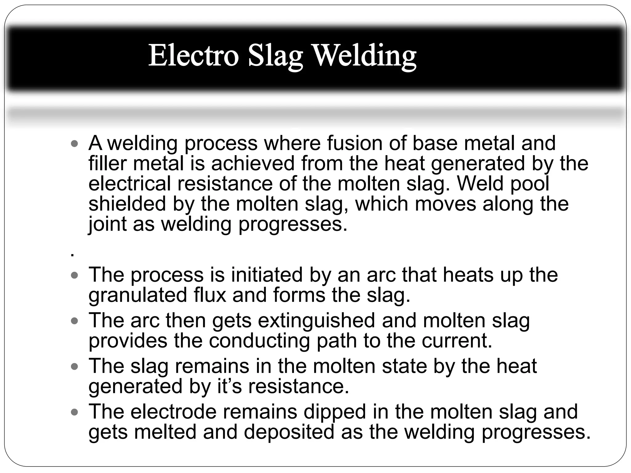
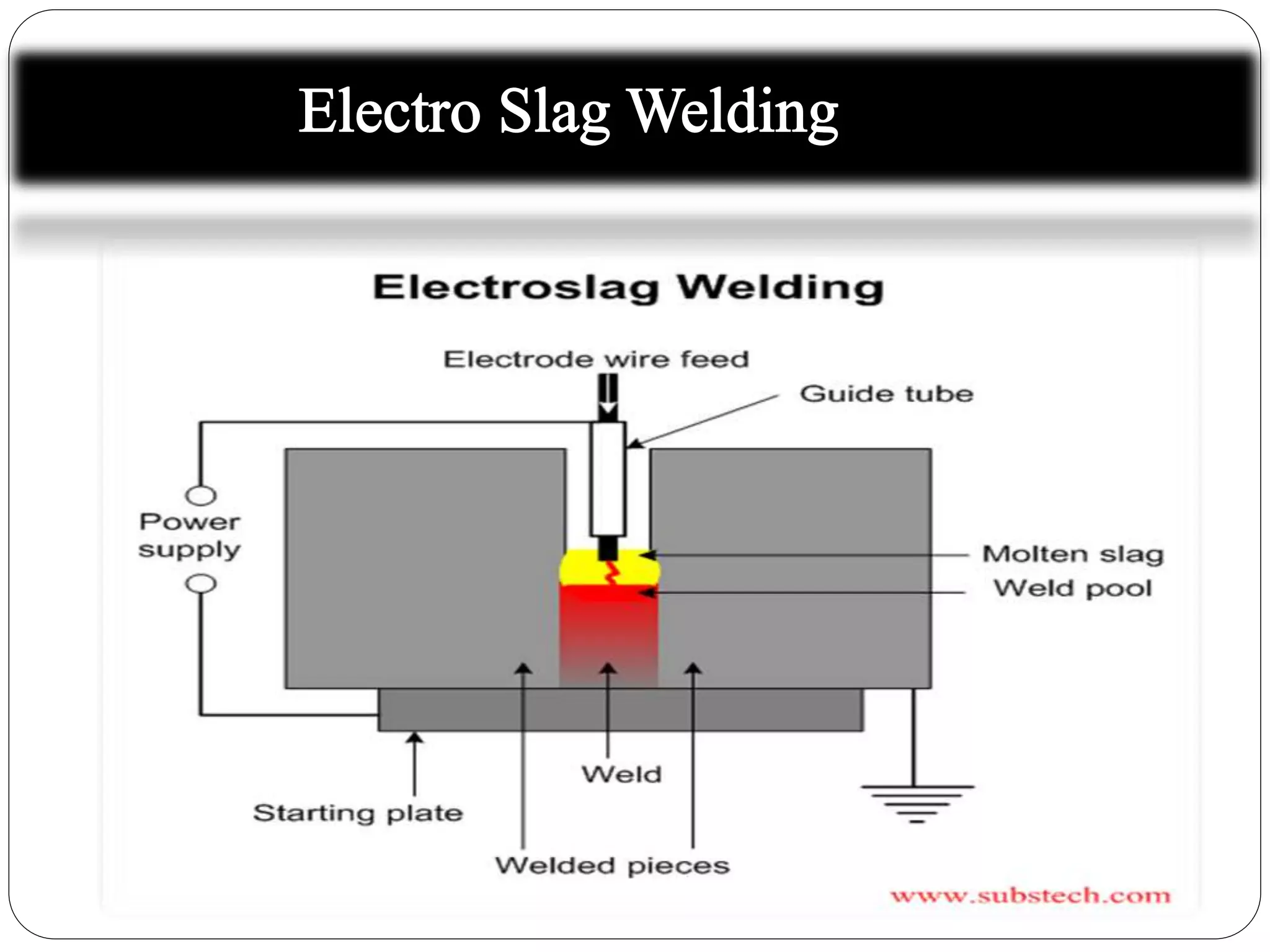
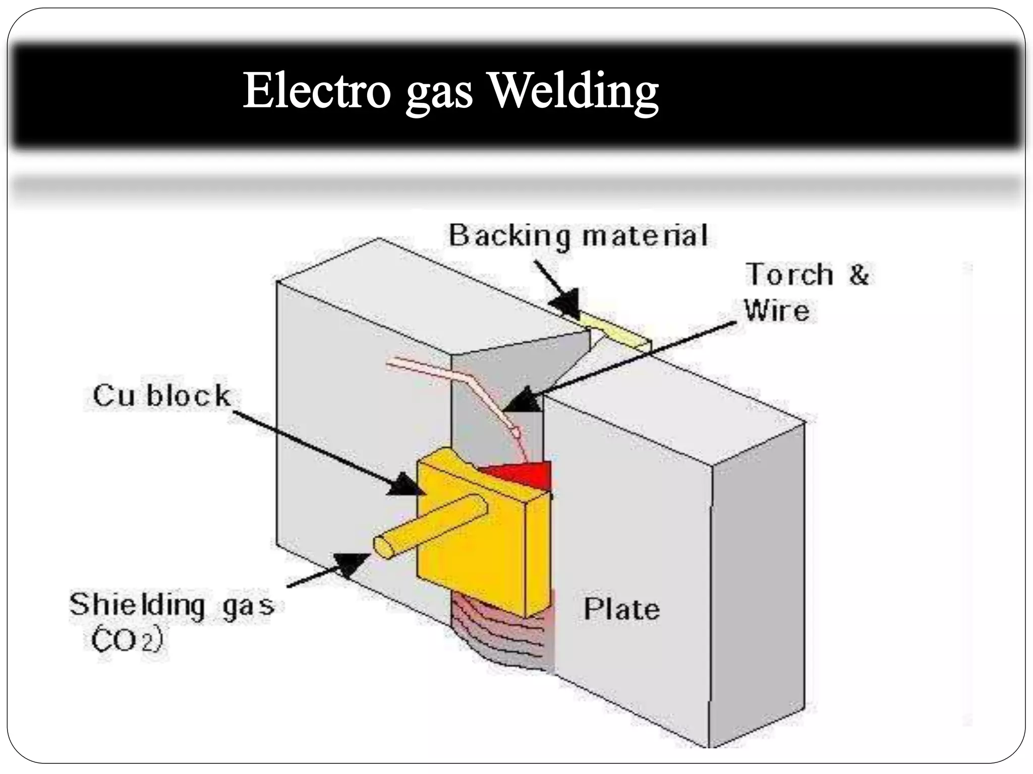
High Profile Call Girls Nashik Megha 7001305949 Independent Escort Service Na...
Electro Slag and Electro Welding
1. Group D
Ali Sher (E12-333)
Ehsan Shehroz (E12-332)
Nauman Aslam (E12-330)
Department of Metallurgy & Materials
Engineering
University of the Punjab, Lahore
2.
3. A welding process where fusion of base metal and
filler metal is achieved from the heat generated by the
electrical resistance of the molten slag. Weld pool
shielded by the molten slag, which moves along the
joint as welding progresses.
.
The process is initiated by an arc that heats up the
granulated flux and forms the slag.
The arc then gets extinguished and molten slag
provides the conducting path to the current.
The slag remains in the molten state by the heat
generated by it’s resistance.
The electrode remains dipped in the molten slag and
gets melted and deposited as the welding progresses.
4.
5. The molten slag bath over the weld pool acts both
as the heat source as well as a shielding medium.
A progressive solidification takes place from
bottom upwards, and always there is a molten
metal pool over the solidifying weld metal.
Welds plates ranging in thickness from 19 to 460
mm.
Types
Two types of electro slag welding ,
Non-consumable electrode guide cum
contact tube
6. Electrode with Non Consumable Guide
One or more electrodes are fed to the molten slag
pool depending on the thickness of the metals
being joined.
Water cooled copper shoes are used on both
sides of the plates to contain the molten metal
and the molten slag.
Shoes move vertically up
Speed of this vertical movement determines the
welding speed
Consistent with the electrode melting and
7. Contact surfaces of the shoes are shaped
concave.
Provides the required amount of reinforcement
on the weld deposit.
As the shoes move up, the solidified weld deposit
gets exposed.
The exposed surfaces are covered with a fine
layer of slag.
Small amounts of flux is added at intervals to
compensate for this consumption of slag.
8. Consumable guide
Metal deposition is from both electrode and the
consumable guide.
The consumable guide provides approximately 5 to
15% of the filler metal.
In this method non sliding shoes are used.
Entire joint height is covered by the shoes.
Shoes are of same length as the joint.
For longer joints, several sets of shoes are
used.
With the progress of the weld as the metal solidifies,
the shoes from below are removed and placed above
9. As the weld current is carried by the guide tube,
Needs to be insulated.
Required insulation may be provided by
Flux coating of the outer surface of the
guide tube.
Insulating tape.
This method can be used to weld sections of
virtually unlimited thickness.
Constant potential DC power source is used
Current rating of 500 to 1000 A.
Load voltages generally range from 30 to 55 V
10. Power Supply
Constant potential DC power source is used
Current rating of 500 to 1000 A.
Load voltages generally range from 30 to 55 V.
Operating Variables
Operating variables differ from those with
conventional arc welding processes.
11. Form Factor
Solidification of molten metal takes place at a
slow rate.
Angle at which the grains meet in the center is
determined by the shape of the molten weld
pool.
Weld pool shape can be expressed by a “form
factor”.
Form factor is the ratio of the weld pool width to
it’s maximum depth.
12. A high factor weld deposit tends to solidify with
Grains meeting at an acute angle.
In case of low form factor,
Grains meet at obtuse angle.
The weld cracking resistance
High in case of acute angles
Low in case of obtuse angle.
Maximum resistance to cracking is obtained with
welds having high form factor.
Form factor alone doesn’t control cracking .
Base metal composition, filler metal composition
and joint restraint have a significant effect on crack
formation.
13. Welding Current
Increasing welding current
Increased heat input
Increased depth of molten weld pool.
Effect of increasing current is to decrease the
form factor and thus lowering the resistance to
cracking.
Generally currents of 500 to 700 A are used with
3.2 mm electrode.
For metals more prone to cracks, current below
500 A used.
14. Welding Voltage
An extremely important variable.
For stable operation voltages within 30 to 55 V
per electrode are used.
Increasing the voltage
Increases the sideways depth of fusion in the
base metal
Increases the width of the weld.
Increases the form factor
Increases resistance to cracking.
With thickness sections, higher voltages are
15. Electrode Oscillation
Oscillation of electrode is generally carried out
horizontally across the thickness.
It distributes the heat and thus helps to obtain
better edge fusion.
Oscillation speeds vary between 8 to 40 mm/s,
with increasing speed to match the plate
thickness.
16. Advantages
Very high deposition rates can be achieved with
ESW
Very thick sections can be welded in a single
pass and more economically.
Thickness up to 450 mm in plain and alloy steels
can be welded without difficulty.
Residual stresses and distortion produced are
lower.
During the electro slag process since no arc
exists no spattering or intense arc flashing
occurs.
17. Limitations
Electro slag welding is not suitable for joints
below 60 mm.
Coarse grain structure of the weld.
Low toughness of the weld.
Only vertical position can be welded.
18.
19. A further development of electro slag welding
process.
Instead of resistance heating of molten
slag, the electrode is melted by the arc
heat in an inert gas environment, very
similar to that of GMAW process.
Very useful for vertical welding of thick plates up
to a thickness of about 100 mm in a single pass.
Led to large cost savings compared to
conventional GMAW process for welding of very
thick steel plates.
20. Solid or flux cored wire electrodes are used.
Produces a smaller heat-affected zone (HAZ)
Better notch toughness as compared to electro
slag welding.
Gives an advantage of extra melting of electrode
wire leading to high deposition rate and produces
less molten base material thereby resulting in
lesser HAZ.
21. Salient Features
It is an automatic welding process.
It welds only in vertical direction.
The weld pool is bound either by two sliding water
cooled copper shoes or a sliding water cooled
copper shoe in the front and ceramic backing
strip at the back.
The electrode is melted by a shielded arc.
Constant current DC power supply is generally
used.
Electrode is kept positive.
22. Process
Once the arc is initiated,
In the arc heat the electrode and the plate edges along
the vertical groove melts forming a weld pool covered side
ways with copper shoes.
In the process the molten material at the lower end of the
groove solidifies and the process continues till it reaches
the upper end.
Synchronization of the feeding of electrode and moving up
of the shoes is extremely important.
Any mismatch will lead to
Arc unstability or
Stubbing of electrode in the molten pool (may lead to
23.
24. Single electrode EGW
To reduce the heat input,
A fine diameter wire is used with a lower
welding current and a narrow groove.
To attain a sound weld bead formation, the weld
wire (nozzle) is oscillated in the plate thickness
direction.
Enables proper welding with adequate
reinforcement on both sides of the plate.
HAZ toughness and welding efficiency
substantially increases.
Is used to weld 50 mm thick steel plates.
25. Double electrode EGW
For plates having thickness greater than 50 mm
single electrode EGW can't be used. Plates of
thickness 50-70 mm is welded by double
electrode EGW process.
Direct current power source is used.
One of the electrode is made positive and the
other is kept negative.
This provides for a stable arc.
If both electrodes have the same polarity,
Arc becomes highly unstable and leads to high
amount of spatter.
26. Also with electrode positive
Wider bead is formed
With less penetration
Negative polarity gives
Narrow bead
With deeper penetration
For a wide single V groove, the electrode on the
wider groove surface is made positive and
electrode on the rear side of the groove is made
negative.
27.
28. Applications
Grain fully applied in Building of
Storage tanks
Vertical Vessels
Blast furnaces
Chemical Furnaces
Ship Building
Thick walled and large diameter pipes
Bridges etc.
29. Advantages
EGW process has higher welding speed.
EGW process welds thicker plates in single pass.
High Deposition Rate as compared to manual
welding.
Welded joints have better mechanical properties
such as impact strength.
Limitations
This process is limited for making vertical weld
joints.
Massive, expensive welding equipment and
guidance system are required.