EV Charging Resources and Technical Assistance for Rural Communities and Trib...
Caterpillar Cat CB-334E and CB-335E Vibratory Compactor (Prefix C3F) Service Repair Manual Instant Download.pdf
1. Shutdown SIS
Previous Screen
Product: VIBRATORY COMPACTOR
Model: CB-335E VIBRATORY COMPACTOR C3F
Configuration: CB-334E CB-335E Vibratory Compactor C3F00001-UP (MACHINE) POWERED BY 3013C Engine
Disassembly and Assembly
CB-334E Series II and CB-335E Series II
Vibratory Compactors
Machine Systems
Media Number -KENR7108-00 Publication Date -01/02/2007 Date Updated -22/02/2007
i02617401
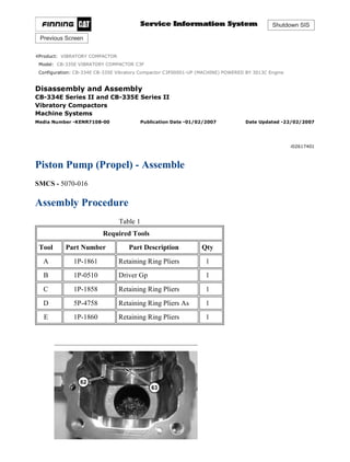
Piston Pump (Propel) - Assemble
SMCS - 5070-016
Assembly Procedure
Table 1
Required Tools
Tool Part Number Part Description Qty
A 1P-1861 Retaining Ring Pliers 1
B 1P-0510 Driver Gp 1
C 1P-1858 Retaining Ring Pliers 1
D 5P-4758 Retaining Ring Pliers As 1
E 1P-1860 Retaining Ring Pliers 1
1/15
CB-334E CB-335E Vibratory Compactor C3F00001-UP (MACHINE) POWERED B...
2021/8/16
https://127.0.0.1/sisweb/sisweb/techdoc/techdoc_print_page.jsp?returnurl=/sis...
4. 7. Install bearing (55) onto shaft (53) .
8. Use Tooling (E) in order to install retaining ring (54) .
Illustration 7 g01310833
9. Install shaft (53) and O-ring seal (52) .
Illustration 8 g01310832
10. Install lip seal (51) into cover (50) .
4/15
CB-334E CB-335E Vibratory Compactor C3F00001-UP (MACHINE) POWERED B...
2021/8/16
https://127.0.0.1/sisweb/sisweb/techdoc/techdoc_print_page.jsp?returnurl=/sis...
5. Illustration 9 g01310830
11. Install cover (50) .
12. Use Tooling (D) in order to Install retaining ring (49) .
Illustration 10 g01310849
Illustration 11 g01311061
5/15
CB-334E CB-335E Vibratory Compactor C3F00001-UP (MACHINE) POWERED B...
2021/8/16
https://127.0.0.1/sisweb/sisweb/techdoc/techdoc_print_page.jsp?returnurl=/sis...
6. Personal injury can result from being struck by parts propelled by a
released spring force.
Make sure to wear all necessary protective equipment.
Follow the recommended procedure and use all recommended tooling to
release the spring force.
13. Install washer (46), spring (47), and washer (48) into barrel (42) .
14. Use Tooling (B), Tooling (C), and a suitable press in order to install retaining ring (45) .
Illustration 12 g01310844
15. Install pins (44) and retainer (43) .
Illustration 13 g01310848
6/15
CB-334E CB-335E Vibratory Compactor C3F00001-UP (MACHINE) POWERED B...
2021/8/16
https://127.0.0.1/sisweb/sisweb/techdoc/techdoc_print_page.jsp?returnurl=/sis...
8. Illustration 16 g01310843
19. Install rotating group (37) and gasket (38) .
Illustration 17 g01310837
20. Install block (35) and gasket (36) .
Illustration 18 g01310828
Personal injury can result from being struck by parts propelled by a
released spring force.
Make sure to wear all necessary protective equipment.
Follow the recommended procedure and use all recommended tooling to
release the spring force.
8/15
CB-334E CB-335E Vibratory Compactor C3F00001-UP (MACHINE) POWERED B...
2021/8/16
https://127.0.0.1/sisweb/sisweb/techdoc/techdoc_print_page.jsp?returnurl=/sis...
9. 21. Install spring (31), washer (32), and nuts (33) onto bolt (34) .
Illustration 19 g01310826
Personal injury can result from being struck by parts propelled by a
released spring force.
Make sure to wear all necessary protective equipment.
Follow the recommended procedure and use all recommended tooling to
release the spring force.
22. Use Tooling (A) in order to install retaining ring (30) .
Illustration 20 g01310825
9/15
CB-334E CB-335E Vibratory Compactor C3F00001-UP (MACHINE) POWERED B...
2021/8/16
https://127.0.0.1/sisweb/sisweb/techdoc/techdoc_print_page.jsp?returnurl=/sis...
12. Illustration 26 g01311069
Personal injury can result from being struck by parts propelled by a
released spring force.
Make sure to wear all necessary protective equipment.
Follow the recommended procedure and use all recommended tooling to
release the spring force.
29. Install the O-ring seals, poppet (14), spring (13), retainers (11), and plug assembly (9) .
30. Repeat Step 29 for the opposite side.
31. Install the O-ring seals, check valve (10), and check valve (12) .
32. Install the O-ring seals, plug (16), and plugs (15) .
12/15
CB-334E CB-335E Vibratory Compactor C3F00001-UP (MACHINE) POWERED ...
2021/8/16
https://127.0.0.1/sisweb/sisweb/techdoc/techdoc_print_page.jsp?returnurl=/sis...
13. Illustration 27 g01310817
33. Install port plate (8) .
Illustration 28 g01310813
Personal injury can result from being struck by parts propelled by a
released spring force.
Make sure to wear all necessary protective equipment.
Follow the recommended procedure and use all recommended tooling to
release the spring force.
34. Install head (7) and bolts (6) .
13/15
CB-334E CB-335E Vibratory Compactor C3F00001-UP (MACHINE) POWERED ...
2021/8/16
https://127.0.0.1/sisweb/sisweb/techdoc/techdoc_print_page.jsp?returnurl=/sis...
15. End By: Install the piston pump. Refer to Disassembly and Assembly, "Piston Pump (Propel) -
Install".
Copyright 1993 - 2021 Caterpillar Inc.
All Rights Reserved.
Private Network For SIS Licensees.
Mon Aug 16 23:30:16 UTC+0800 2021
15/15
CB-334E CB-335E Vibratory Compactor C3F00001-UP (MACHINE) POWERED ...
2021/8/16
https://127.0.0.1/sisweb/sisweb/techdoc/techdoc_print_page.jsp?returnurl=/sis...
16. Shutdown SIS
Previous Screen
Product: VIBRATORY COMPACTOR
Model: CB-335E VIBRATORY COMPACTOR C3F
Configuration: CB-334E CB-335E Vibratory Compactor C3F00001-UP (MACHINE) POWERED BY 3013C Engine
Disassembly and Assembly
CB-334E Series II and CB-335E Series II
Vibratory Compactors
Machine Systems
Media Number -KENR7108-00 Publication Date -01/02/2007 Date Updated -22/02/2007
i02624338
Piston Pump (Propel) - Install
SMCS - 5070-012
Installation Procedure
Illustration 1 g01315179
1. Install the O-ring seal and gear pump (1) to piston pump (4) and install bolts (12) .
1/4
CB-334E CB-335E Vibratory Compactor C3F00001-UP (MACHINE) POWERED B...
2021/8/16
https://127.0.0.1/sisweb/sisweb/techdoc/techdoc_print_page.jsp?returnurl=/sis...
17. Illustration 2 g01315082
2. Attach a suitable lifting device to piston pump (4). Install piston pump (4) and gear pump
(1) as a unit. Install bolts (11). The weight of the piston pump and the gear pump is
approximately 61 kg (135 lb).
Illustration 3 g01315081
3. Connect hose assembly (10) to piston pump (4) .
Illustration 4 g01315080
2/4
CB-334E CB-335E Vibratory Compactor C3F00001-UP (MACHINE) POWERED B...
2021/8/16
https://127.0.0.1/sisweb/sisweb/techdoc/techdoc_print_page.jsp?returnurl=/sis...
19. Illustration 7 g01315008
7. Connect hose assembly (3) and hose assemblies (2) to gear pump (1) .
8. Fill the hydraulic oil tank with hydraulic oil. Refer to Operation and Maintenance Manual
for the correct procedure.
Copyright 1993 - 2021 Caterpillar Inc.
All Rights Reserved.
Private Network For SIS Licensees.
Mon Aug 16 23:31:11 UTC+0800 2021
4/4
CB-334E CB-335E Vibratory Compactor C3F00001-UP (MACHINE) POWERED B...
2021/8/16
https://127.0.0.1/sisweb/sisweb/techdoc/techdoc_print_page.jsp?returnurl=/sis...
20. Shutdown SIS
Previous Screen
Product: VIBRATORY COMPACTOR
Model: CB-335E VIBRATORY COMPACTOR C3F
Configuration: CB-334E CB-335E Vibratory Compactor C3F00001-UP (MACHINE) POWERED BY 3013C Engine
Disassembly and Assembly
CB-334E Series II and CB-335E Series II
Vibratory Compactors
Machine Systems
Media Number -KENR7108-00 Publication Date -01/02/2007 Date Updated -22/02/2007
i02624562
Drum and Drum Support - Remove
SMCS - 6605-011-S4; 6605-011
Removal Procedure
Table 1
Required Tools
Tool Part Number Part Description Qty
A 6V-6146 Load Leveling Beam 1
B 138-7574 Link Bracket 2
C 1P-2321 Combination Puller 1
Start By:
A. Remove the vibratory motor. Refer to Disassembly and Assembly, "Gear Motor (Vibratory)
- Remove".
Hot oil and hot components can cause personal injury. Do not allow hot
oil or hot components to contact skin.
At operating temperature, the engine coolant is hot and under pressure.
Steam can cause personal injury.
1/6
CB-334E CB-335E Vibratory Compactor C3F00001-UP (MACHINE) POWERED B...
2021/8/16
https://127.0.0.1/sisweb/sisweb/techdoc/techdoc_print_page.jsp?returnurl=/sis...
21. Check the coolant level only after the engine has been stopped and the
cooling system pressure cap is cool enough to touch with your bare
hand.
Remove the cooling system pressure cap slowly to relieve pressure.
Cooling system conditioner contains alkali. Avoid contact with the skin
and eyes to prevent personal injury.
NOTICE
Care must be taken to ensure that fluids are contained during
performance of inspection, maintenance, testing, adjusting and repair
of the product. Be prepared to collect the fluid with suitable containers
before opening any compartment or disassembling any component
containing fluids.
Refer to Special Publication, NENG2500, "Caterpillar Tools and Shop
Products Guide" for tools and supplies suitable to collect and contain
fluids on Caterpillar products.
Dispose of all fluids according to local regulations and mandates.
Note: Put identification marks on all hoses, on all hose assemblies, on all wires, and on all tube
assemblies for installation purposes. Plug all hose assemblies and all tube assemblies. This helps
to prevent fluid loss, and this helps to keep contaminants from entering the system.
Illustration 1 g00622269
1. Disconnect water supply hose (1) from the spray bar.
2. Remove bolts (3) and remove the scraper and spray bar assembly (2) .
2/6
CB-334E CB-335E Vibratory Compactor C3F00001-UP (MACHINE) POWERED B...
2021/8/16
https://127.0.0.1/sisweb/sisweb/techdoc/techdoc_print_page.jsp?returnurl=/sis...
22. Illustration 2 g01315304
3. Remove bolts (4) and cover (5) from the drum support.
4. Disconnect hose assemblies (6) from piston motor (7) .
5. Move the hose assemblies out of the way on both sides of the machine.
Illustration 3 g01082270
6. Attach Tooling (A), Tooling (B), and a suitable lifting device to each drum support, as
shown. The combined weight of the drum and drum supports is approximately 675 kg (1490
lb).
7. Use the suitable lifting device to slightly raise the drum off the ground. Place suitable blocks
under the frame, as shown. Lower the machine so the machine rests on the wood blocks.
Maintain a small amount of tension in the lifting chains.
8. Remove bolts (8) which fasten the right and left drum supports to the machine.
9. Use the suitable lifting device to carefully lower the drum away from the machine.
10. Use the suitable lifting device to carefully move the drum away from the machine.
3/6
CB-334E CB-335E Vibratory Compactor C3F00001-UP (MACHINE) POWERED B...
2021/8/16
https://127.0.0.1/sisweb/sisweb/techdoc/techdoc_print_page.jsp?returnurl=/sis...
23. Illustration 4 g01083109
11. Block the drum, as shown.
12. Attach a suitable lifting device to drum support (9). The weight of the drum support is
approximately 66 kg (146 lb).
13. Remove bolts (10) and use a hoist to remove drum support (12) .
Illustration 5 g01083126
14. Attach a suitable lifting device to drum support (vibratory motor side) (11). The weight of
drum support (11) and plate assembly (13) is approximately 135 kg (298 lb).
15. Remove bolts (12) and use a suitable lifting device to remove drum support (11) and plate
assembly (11) from the drum.
4/6
CB-334E CB-335E Vibratory Compactor C3F00001-UP (MACHINE) POWERED B...
2021/8/16
https://127.0.0.1/sisweb/sisweb/techdoc/techdoc_print_page.jsp?returnurl=/sis...
24. Illustration 6 g01083137
16. Position drum support (11) and attach a suitable lifting device, as shown.
Note: Mark plate (15) and drum support (11) for assembly purposes.
17. Remove bolts (14) and remove plate (15) .
Illustration 7 g01083150
18. Remove retaining plate (16) .
5/6
CB-334E CB-335E Vibratory Compactor C3F00001-UP (MACHINE) POWERED B...
2021/8/16
https://127.0.0.1/sisweb/sisweb/techdoc/techdoc_print_page.jsp?returnurl=/sis...
25. Illustration 8 g01083207
19. Use a Tooling (C) in order to separate drum support (11) from plate assembly (13) .
Copyright 1993 - 2021 Caterpillar Inc.
All Rights Reserved.
Private Network For SIS Licensees.
Mon Aug 16 23:32:07 UTC+0800 2021
6/6
CB-334E CB-335E Vibratory Compactor C3F00001-UP (MACHINE) POWERED B...
2021/8/16
https://127.0.0.1/sisweb/sisweb/techdoc/techdoc_print_page.jsp?returnurl=/sis...
26. Shutdown SIS
Previous Screen
Product: VIBRATORY COMPACTOR
Model: CB-335E VIBRATORY COMPACTOR C3F
Configuration: CB-334E CB-335E Vibratory Compactor C3F00001-UP (MACHINE) POWERED BY 3013C Engine
Disassembly and Assembly
CB-334E Series II and CB-335E Series II
Vibratory Compactors
Machine Systems
Media Number -KENR7108-00 Publication Date -01/02/2007 Date Updated -22/02/2007
i05006661
Drum and Drum Support - Install
SMCS - 6605-012-S4; 6605-012
Installation Procedure
Table 1
Required Tools
Tool Part Number Part Description Qty
A 6V-6146 Load Leveling Beam 1
B 138-7574 Load Leveling Beam 1
C - Loctite 5127 -
Illustration 1 g01083207
1/5
CB-334E CB-335E Vibratory Compactor C3F00001-UP (MACHINE) POWERED B...
2021/8/16
https://127.0.0.1/sisweb/sisweb/techdoc/techdoc_print_page.jsp?returnurl=/sis...
27. 1. Position drum support (11) onto plate assembly (13) .
Illustration 2 g01083150
2. Install retaining plate (16) .
Note: Fill the cavity of retaining plate (16) which faces toward the bearing with grease.
Illustration 3 g01083137
3. Apply Tooling (C) to the mating surfaces of plate (15) and drum support (11) . Position
retaining plate (16) onto drum support (11) . Install bolts (14) .
2/5
CB-334E CB-335E Vibratory Compactor C3F00001-UP (MACHINE) POWERED B...
2021/8/16
https://127.0.0.1/sisweb/sisweb/techdoc/techdoc_print_page.jsp?returnurl=/sis...
28. Illustration 4 g01083126
4. Attach a suitable lifting device to drum support (11) . The weight of the drum support (11)
is approximately 135 kg (298 lb).
5. Position drum support (11) and plate assembly (13) , as shown. The large opening on plate
assembly (13) should be in-line with the welded boss on the opposite side of the drum.
6. Install bolts (12) which fasten plate assembly (13) to the drum.
Illustration 5 g01083109
7. Attach a suitable lifting device to drum support (9) . The weight of drum support (9) is
approximately 66 kg (146 lb).
8. Use the suitable lifting device to position drum support (9) , as shown. Install bolts (10) .
3/5
CB-334E CB-335E Vibratory Compactor C3F00001-UP (MACHINE) POWERED B...
2021/8/16
https://127.0.0.1/sisweb/sisweb/techdoc/techdoc_print_page.jsp?returnurl=/sis...
29. Suggest:
If the above button click is invalid.
Please download this document
first, and then click the above link
to download the complete manual.
Thank you so much for reading
30. Illustration 6 g01082270
9. Attach Tooling (A) , Tooling (B) , and a suitable lifting device to each drum support, as
shown. The combined weight of the drum and drum supports is approximately 675 kg (1490
lb).
10. Use the suitable lifting device to carefully position the drum and drum supports to the
original location.
11. Install bolts (8) which fasten the right and left drum supports to the machine.
12. Use the suitable lifting device to raise the machine from the suitable blocks. Remove the
suitable blocks and carefully lower the machine to the ground.
13. Move all the hose assemblies to the original position.
Note: Repeat step 13 for the opposite side.
Illustration 7 g01315304
14. Connect hose assemblies (6) to piston motor (7) .
15. Position cover (5) onto the drum support and install bolts (4) .
4/5
CB-334E CB-335E Vibratory Compactor C3F00001-UP (MACHINE) POWERED B...
2021/8/16
https://127.0.0.1/sisweb/sisweb/techdoc/techdoc_print_page.jsp?returnurl=/sis...