Design of an autonomous ornithopter with live video reception for military surveillance

Abstract In recent years flying by propelled wings, also called as Ornithopter, has been an area of interest because of its application to Micro Aerial Vehicles (MAVs). In the field of Defence and during the war of Iraq, a need for live surveillance within a close distance was felt, which lead to research of various techniques for live surveillance in the battle ground to provide the necessary intelligence to the troops in the line of action. These miniature vehicles seek to mimic small birds to achieve never before seen agility in flight. In order to better study the control of flapping wing flight we have researched and modelled a large scale ornithopter called the ‘Garuda’. The ‘Garuda’ is capable of carrying a microcontroller, sensor package and an on board surveillance camera to transmit live video feed to the receiver in real time. The design takes special care to optimize payload capacity, crash survivability, and field repair abilities. This model has applications in the field of defence spy surveillance over enemy territories without being detected or arousing suspicion. Keywords: Ornithopter, Military, Surveillance, Autonomous, Video

Recommended
More Related Content
What's hot
What's hot (20)
Similar to Design of an autonomous ornithopter with live video reception for military surveillance
Similar to Design of an autonomous ornithopter with live video reception for military surveillance (20)
More from eSAT Journals
More from eSAT Journals (20)
Recently uploaded
Recently uploaded (20)
Design of an autonomous ornithopter with live video reception for military surveillance
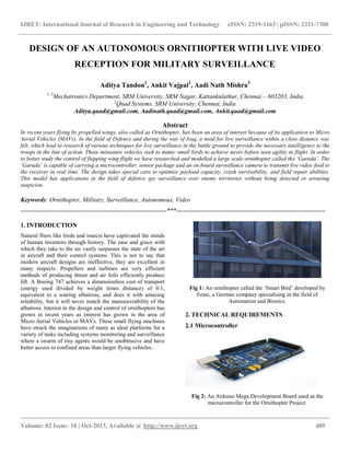
- 1. IJRET: International Journal of Research in Engineering and Technology eISSN: 2319-1163 | pISSN: 2321-7308 __________________________________________________________________________________________ Volume: 02 Issue: 10 | Oct-2013, Available @ http://www.ijret.org 489 DESIGN OF AN AUTONOMOUS ORNITHOPTER WITH LIVE VIDEO RECEPTION FOR MILITARY SURVEILLANCE Aditya Tandon1 , Ankit Vajpai2 , Aadi Nath Mishra3 1, 3 Mechatronics Department, SRM University, SRM Nagar, Kattankulathur, Chennai – 603203, India 2 Quad Systems, SRM University, Chennai, India Aditya.quad@gmail.com, Aadinath.quad@gmail.com, Ankit.quad@gmail.com Abstract In recent years flying by propelled wings, also called as Ornithopter, has been an area of interest because of its application to Micro Aerial Vehicles (MAVs). In the field of Defence and during the war of Iraq, a need for live surveillance within a close distance was felt, which lead to research of various techniques for live surveillance in the battle ground to provide the necessary intelligence to the troops in the line of action. These miniature vehicles seek to mimic small birds to achieve never before seen agility in flight. In order to better study the control of flapping wing flight we have researched and modelled a large scale ornithopter called the ‘Garuda’. The ‘Garuda’ is capable of carrying a microcontroller, sensor package and an on board surveillance camera to transmit live video feed to the receiver in real time. The design takes special care to optimize payload capacity, crash survivability, and field repair abilities. This model has applications in the field of defence spy surveillance over enemy territories without being detected or arousing suspicion. Keywords: Ornithopter, Military, Surveillance, Autonomous, Video ----------------------------------------------------------------------***----------------------------------------------------------------------- 1. INTRODUCTION Natural fliers like birds and insects have captivated the minds of human inventors through history. The ease and grace with which they take to the air vastly surpasses the state of the art in aircraft and their control systems. This is not to say that modern aircraft designs are ineffective, they are excellent in many respects. Propellers and turbines are very efficient methods of producing thrust and air foils efficiently produce lift. A Boeing 747 achieves a dimensionless cost of transport (energy used divided by weight times distance) of 0.1, equivalent to a soaring albatross, and does it with amazing reliability, but it will never match the manoeuvrability of the albatross. Interest in the design and control of ornithopters has grown in recent years as interest has grown in the area of Micro Aerial Vehicles or MAVs. These small flying machines have struck the imaginations of many as ideal platforms for a variety of tasks including systems monitoring and surveillance where a swarm of tiny agents would be unobtrusive and have better access to confined areas than larger flying vehicles. Fig 1: An ornithopter called the ‘Smart Bird’ developed by Festo, a German company specialising in the field of Automation and Bionics. 2. TECHNICAL REQUIREMENTS 2.1 Microcontroller Fig 2: An Arduino Mega Development Board used as the microcontroller for the Ornithopter Project.
- 2. IJRET: International Journal of Research in Engineering and Technology eISSN: 2319-1163 | pISSN: 2321-7308 __________________________________________________________________________________________ Volume: 02 Issue: 10 | Oct-2013, Available @ http://www.ijret.org 490 The selection of the microcontroller to base the rest of the system on is one of the most defining decisions of the design process because it makes up the largest amount of additional payload weight. Because the scaling of the robot depends on the payload capacity needed the computer choice will have a long chain of effects down the design process. The Arduino based controller has been used because of its versatility and user friendly control system development.The single board Arduino Mega has on board analog to digital converter, several I/O boards to interface with servos and wireless communication.The controller itself weighs around 100gms but with servos and wireless module the weight increases to roughly 400g. The Arduino itself is an open source hardware which has a large range of use and is much more compact and lightweight. The software development environment has a steep learning curve and all of the software is to be written in C. 2.2 Battery Fig 3: An 11.1 V, 1550mAh Lithium Polymer high discharge battery. The battery used is a three cell lithium polymer pack, the standard for high performance machines like airplanes on this scale because it has the best power and energy to weight ratios available. Power density is the main concern at the initial stages of the project because flights aren't expected to last for long which would make power output the limiting factor for the battery. A lithium polymer battery can be discharged at up to 10 times its capacity (commonly referred to as 10C) with specially selected batteries capable of continuous discharge up to 25C which makes it able to deliver the short bursts of power that the ornithopter needs to flap during short test flights. Lithium phosphate batteries produced by A123 were also investigated because they have similar characteristics but the cell sizes available are too large to make a suitably lightweight pack at the correct voltage. The cell price of the lithium phosphate batteries works out to a pack at about half the price of the lithium polymer pack. In addition to this the lithium phosphate cells are much less sensitive to overcharging which causes lithium polymer batteries to violently explode. Because of potential cost and safety advantages of the lithium phosphate cells over the lithium polymer cells they may be further investigated in the future. As the current drawn from the motor wasn't yet known a standard battery, 1200mAh at 11.4V and 93 grams, is chosen for the weight calculation. 2.3 Sensors Fig 4: An MPU-9150 9 Axis Inertial Mass Unit module with Analog Output. Courtesy: Spark fun Electronics 2.4 MPU – 9150 A 9 Axis Inertial Mass Unit to know the exact orientation of the Ornithopter at any instance and to also quantitatively measure all physical forces acting on the payload The IMU package consists of a 3 Axis Accelerometer, a 3 Axis Gyroscope, a Digital Motion Processor and a 3 Axis Digital Compass. Using these values of Acceleration, Force and Direction we are able to estimate the orientation of the Ornithopter in space and hence manoeuvre it in the requisite manner. 2.5 Data Logging – Micro SD Card Arrangement put to use to record and store all sensor and flight data of the Balloon Sat from launch to recovery. The recovered data is thus used to support theoretical experiments and help infer results as well as plot useful information graphs. 2.6 Battery Level Monitor A voltage divider is created and thus the Battery levels on board are mapped and data is stored for further studies on battery consumption and the Ornithopter flight time.
- 3. IJRET: International Journal of Research in Engineering and Technology eISSN: 2319-1163 | pISSN: 2321-7308 __________________________________________________________________________________________ Volume: 02 Issue: 10 | Oct-2013, Available @ http://www.ijret.org 491 2.7 Ls20031 GPS 5HZ Receiver The LS20031 GPS receiver is a complete GPS smart antenna receiver that includes an embedded antenna and GPS receiver circuits. This low-cost unit outputs an astounding amount of position information 5 times a second. The receiver is based on the proven technology found in LOCOSYS 66 channel GPS SMD type receivers that use MediaTek chip solution. 3. HARDWARE INTERFACE Fig 5: A CC2500 Serial Transceiver Module with SPI Interface as shown. Courtesy: iLabs Conventional hobby servos like those used on model aircraft use a pulse width modulated signal with a period of about 40hz and a pulse width of between 1 and 2 milliseconds which corresponds to the desired absolute position of the servo's output drive. Because the computer system's main interface is over RS232 serial, a conversion system is needed. For the network communication, a CC2500 serial transceiver is used which has an RS232 interface. The CC2500 transceiver could also be connected to the Arduino microcontroller using an Arduino shield or else be coupled with an SPI Interface. The drive motor controller sits between the serial to PWM servo controller and the motor and uses that signal to control a high current driver suitable for the power requirements of the large motor. This is again a standard radio control airplane part and a JETI Model Advance 30 brushless motor speed controller was chosen for this application because of its past use in the lab. The speed controller is designed to handle 30 amps of current which was considered to be an upper bound of power required, about 300 watts at the 11.4 volts the battery pack runs at. Figure 6: Main drive motor speed controller. Converts the PWM control signal into the appropriate waveform to drive the high current brushless motor Fig 7: Block diagram of the overall electronics system configuration. 4. MOTORS AND GEAR RATIO Figure 8: A BLDC Motor The motor used in the flapping mechanism of the Ornithopter is a Brushless DC Motor with 5000 RPM. A gear reduction ratio of 24:1 is to be used, giving a shaft speed of roughly 210 RPM.
- 4. IJRET: International Journal of Research in Engineering and Technology eISSN: 2319-1163 | pISSN: 2321-7308 __________________________________________________________________________________________ Volume: 02 Issue: 10 | Oct-2013, Available @ http://www.ijret.org 492 Figure 9: Side view of the complete gearbox showing the motor mounted and the configuration of the transmission gears. 5. TAIL AND WING The tail section of the ornithopter is responsible for both of the controllable degrees of freedom aside from the ability to throttle the drive motor. The tail of the Garuda is set up with one servo directly connected to the tail at an angle and another further up the body which rocks it via a linkage. Mounting the rudder servo at an angle is important because with a single control surface the elevator and rudder are naturally coupled, moving the rudder servo makes the tail also move in the vertical direction unless it's at zero angle where it doesn't have any control authority anyway. Figure 10: The tail section of the Kestrel. The tail uses a clever configuration to decouple the elevator and rudder actions With the tail at an angle to the rudder servo it allows the servo to be held into the zero angle position with respect to the ornithopter body and while the tail stays near the trimmed position for horizontal light. This causes the tail to move in a bowl shaped trajectory decoupled from the elevator action and is much easier to control by a human pilot. It does not solve the problem when the elevator servo moves the tail out of the trimmed horizontal position, but being able to exploit that is a big advantage where it applies. The wings have a triangular support structure made from carbon rods. A main spar runs along the leading edge of the wing and a strut connects from the rear of the ornithopters body to a point near the tip of the main spar. From this strut there are several smaller carbon rods that project to the edge of the wing which are somewhat free to move. This results in a fanning motion from the trailing edge of the wing that produces thrust while the leading edge is aping up and down which directly contributes a part of the lift in addition to the conventional lift coming from airflow over the wing. Figure 11: An image showing the flapping of the wings of ‘Kestrel’, an ornithopter whose design is similar to ‘Garuda’ 6. MAIN FRAME The main frame of the ornithopter is a surprisingly simple component from a design standpoint. Because the aping mechanism is contained fully within the gearbox frame the main frame of the machine serves mainly to provide mounting locations for the rear wing mounts, electronic components, battery, and tail assembly. There are two directions to go with the frame design, either a single at plate which relies on its own thickness for stillness, or a three dimensional design made from much thinner material that gets its stillness from the truss-like structure. If the frame had to be very still the second option would make for a much lighter and stronger option, but in this case the frame really doesn't have to be very still in all directions. The rear wing mount actually holds the frame from flexing in the direction a sheet would be most weak because the wing spars form a very large and still triangle. What this amounts to is that while the more complicated structure is often the higher stillness and lower
- 5. IJRET: International Journal of Research in Engineering and Technology eISSN: 2319-1163 | pISSN: 2321-7308 __________________________________________________________________________________________ Volume: 02 Issue: 10 | Oct-2013, Available @ http://www.ijret.org 493 weight option it doesn't come with much advantage in this case. The frame is vastly easier to design and fabricate and may even be lighter. Because the frame is really just a collection of mounting locations for the rest of the components it's relatively easy to design. The one major specification that must be paid attention to is the location of the center of gravity. Because the data needed to work out the correct location theoretically isn't available this was also scaled up from the Kestrel where the location was experimentally determined from flight testing to be about 4 inches behind the main wing spar. The material to be used for the space frame tubular structure is carbon fibre and the external profiling of the ornithopter is done using polyurethane foam or aluminium mesh.. Figure 12: An image showing the space frame structure with the motor and gear assembly of ‘Kestrel’, an ornithopter whose design is similar to ‘Garuda’. 7. LIVE VIDEO RECEPTION A micro camera compatible with the controller has been mounted the ornithopter to provide live surveillance. The live feedback from the ornithopter will be obtained off board on an LCD display. The surveillance system has a transmitter that will transmit the live video feed over to the receiver and the video feed can be used for surveillance or as an aid with the GPS location to effectively maneuver the ornithopter. Figure 11: A camera with a wireless transmitter to transmit live video feed. ACKNOWLEDGMENTS We would also like to convey our heartfelt gratitude to Mr. Sivanathan, Assistant professor, Dept of Mechatronics, SRM University for his invaluable guidance throughout the research of the project. REFERENCES [1] Nathan Chronister. Ornithopter with independently controlled wings US Patent 11147044, June 7, 2005 [2] Steven H. Collins, Andy Ruina, Russ Tedrake, and Martijn Wisse. Efficient Bipedal robots based on passive-dynamic walkers. [3] Rick E. Cory. Perching with fixed wings Master's thesis, Massachusetts Institute of Technology, 2008 [4] J.D. DeLaurier. The development and testing of a full- scale piloted ornithopter Canadian Aeronautics and Space Journal, June 1999. [5] J.D. DeLaurier. Ornithopter report update. http://ornithopter.net/Publications/OrnithopterReportUpdate19 July2006.pdf, July 19, 2006. [6] Michael H. Dickinson, Fritz-Olaf Lehmann, and Sanjay P. Sane Wing rotation and the aerodynamic basis of insect flight [7] Robyn Lynn Harmon. Aerodynamic modeling of a flapping membrane wing using motion tracking experiments.University of Maryland, 2008 [8] Warren Hoburg and Russ Tedrake System identification of post stall aero- dynamics for UAV perching In Proceedings of the AIAA Infotech@Aerospace Conference, Seattle, WA, April 2009 [9] Kestrel ornithopter at R&R model aircraft. http://www.randrmodelaircraft.com/Kestrel.htm, 2008. [10] Sean Kinkade. Ornithopter. US Patent 9858922, May 17, 2001. [11]R. Krashanitsa, D. Silin, and S. Shkarayev. Flight dynamics of flapping-wing air vehicle. In Proceedings of the AIAA Atmospheric Flight Mechanics Conference, August 2008. [12] Ornithopter flight dynamics and control. http://www.morpheus.umd.edu/research/apping-wing- flight/ornithopter.html, 2009. [13] Aerodynamics of low reynolds number flyers. Cambridge University Press