Downloaded 635 times
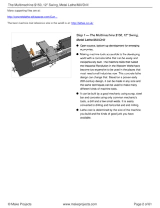


The document provides instructions for building a low-cost metal lathe/mill/drill machine using scrap metal parts and concrete. It describes Lucien Yeomans' early 20th century technique of casting a concrete frame with oversized cavities to accommodate metal parts, allowing for concrete shrinkage. The design calls for mounting metal working parts like the spindle and ways using cement grout within the concrete frame. With scrap metal, common tools and a small amount of welding and concrete, the instructions aim to make an inexpensive but functional machine tool accessible worldwide.


