
Downloaded 54 times
![Proline Promag D 400
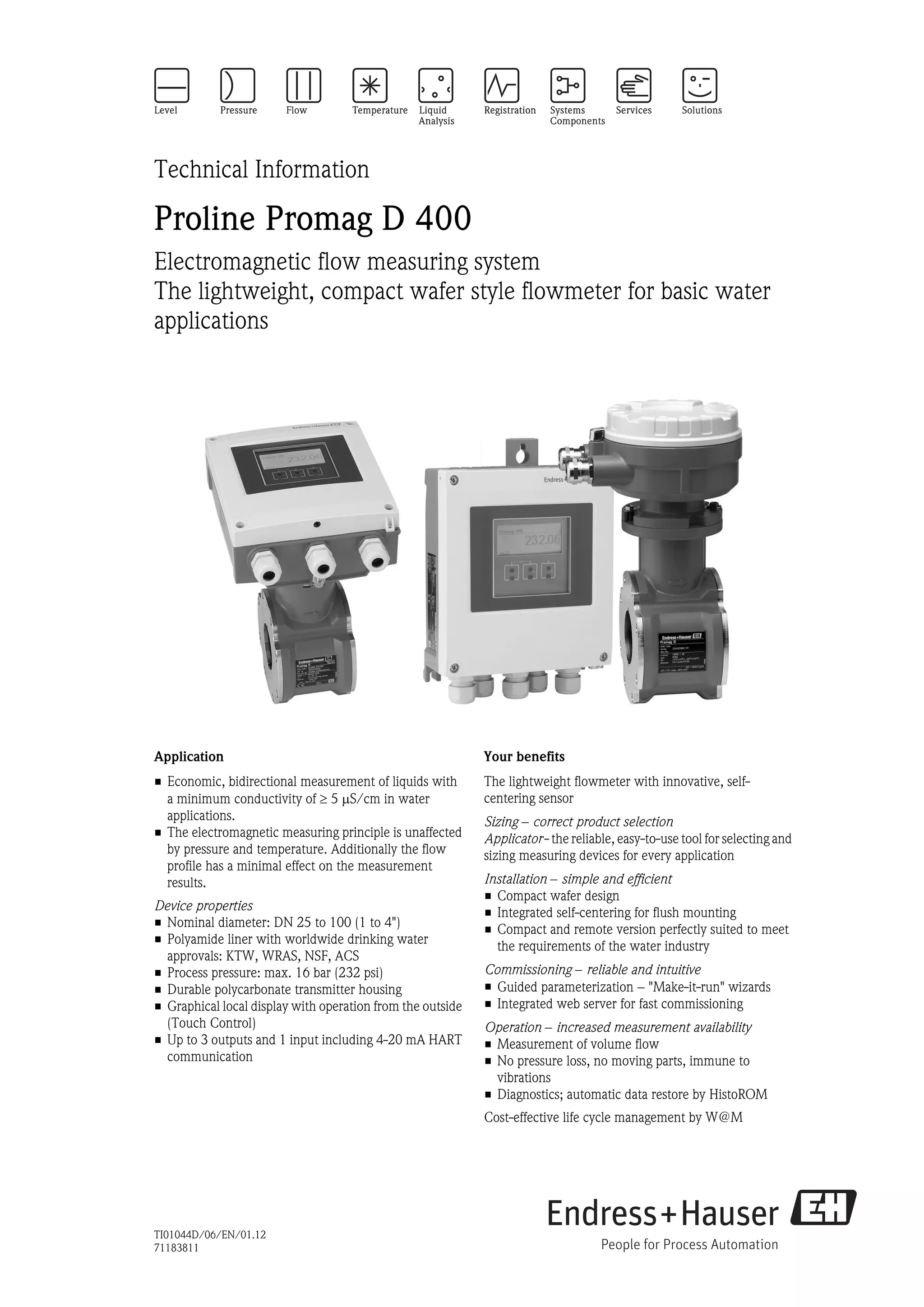
Measuring system The device consists of a transmitter and a sensor.
Two device versions are available:
• Compact version – the transmitter and sensor form a mechanical unit.
• Remote version – the transmitter and sensor are mounted separately from one another.
Transmitter
Promag 400 Device versions and materials:
• Compact housing: polycarbonate plastic
• Wall-mount housing: polycarbonate plastic
Configuration:
• External operation via four-line, illuminated local display with touch control
and guided menus ("Make-it-run" wizards) for applications
• Via operating tools (e.g. FieldCare)
• Via Web browser (e.g. Microsoft Internet Explorer)
A0017117
Sensor
Promag D Nominal diameter range: DN 25 to 100 (1 to 4")
Materials:
• Sensor housing: aluminum coated AlSi10Mg
• Sensor connection housing: aluminum coated AlSi10Mg
• Liner: polyamide
• O-rings: EPDM
• Electrodes: 1.4435/316L
• Ground disks: 1.4301/304
A0017036
Input
Measured variable Direct measured variables
• Volume flow (proportional to induced voltage)
• Electrical conductivity
Calculated measured variables
Mass flow
Measuring range Typically v = 0.01 to 10 m/s (0.03 to 33 ft/s) with the specified accuracy
Flow characteristic values in SI units
Nominal Recommended
Factory settings
diameter flow
Full scale value current
min./max. full scale value Pulse value Low flow cut off
output
(v ~ 0.3/10 m/s (~ 2 pulse/s) (v ~ 0.04 m/s)
(v ~ 2.5 m/s)
[mm] [in] [dm3/min] [dm3/min] [dm3] [dm3/min]
25 1 9 to 300 75 0.5 1
40 1½ 25 to 700 200 1.5 3
50 2 35 to 1 100 300 2.5 5
65 – 60 to 2 000 500 5 8
80 3 90 to 3 000 750 5 12
100 4 145 to 4 700 1 200 10 20
Endress+Hauser 5](https://image.slidesharecdn.com/ti01044den0112prolinepromagd400-130328210344-phpapp01/75/Electromagnetic-flowmeter-Proline-Promag-D-400-5-2048.jpg)
![Proline Promag D 400
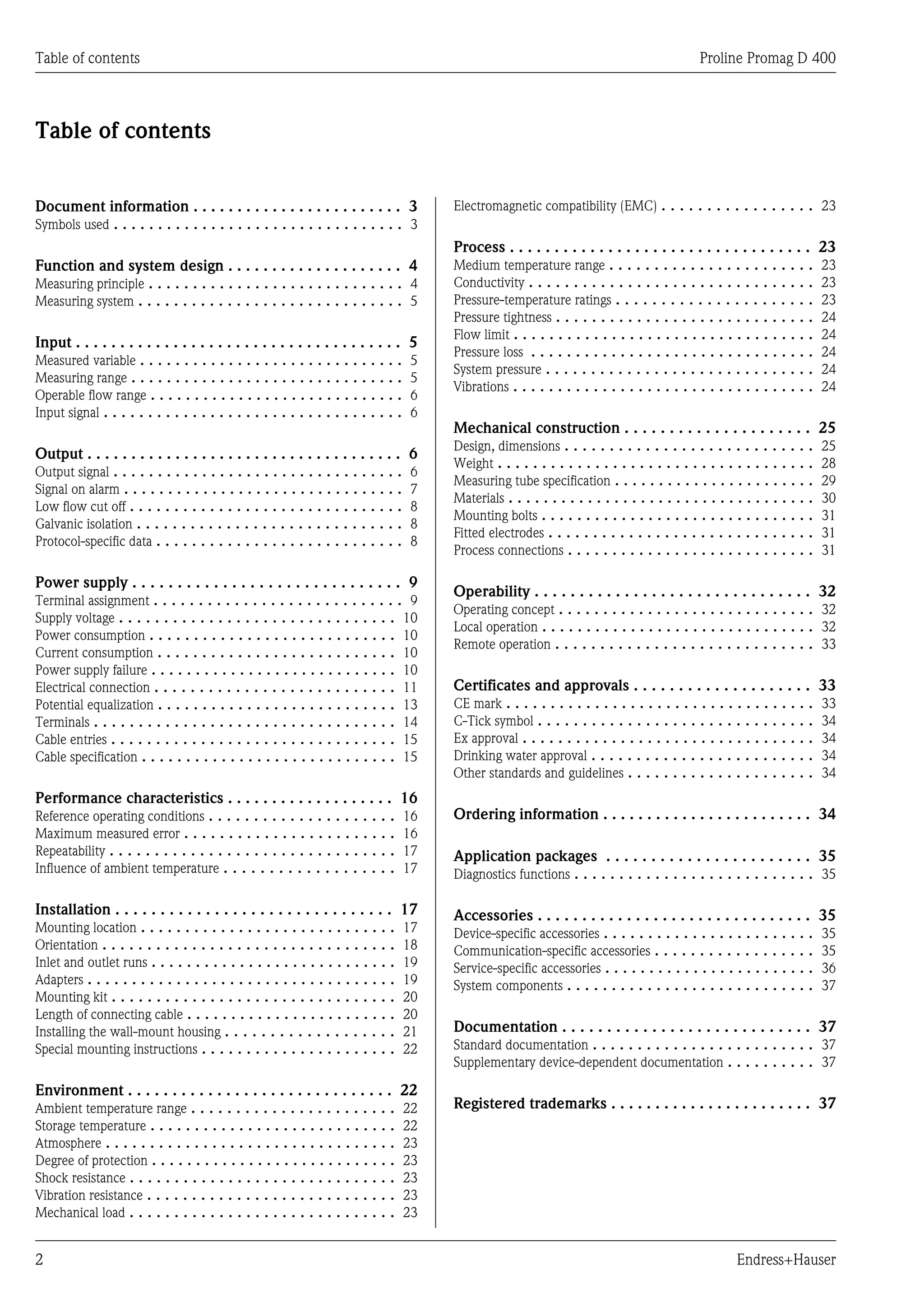
Flow characteristic values in US units
Nominal Recommended
Factory settings
diameter flow
Full scale value current
min./max. full scale value Pulse value Low flow cut off
output
(v ~ 0.3/10 m/s) (~ 2 pulse/s) (v ~ 0.04 m/s)
(v ~ 2.5 m/s)
[in] [mm] [gal/min] [gal/min] [gal] [gal/min]
1 25 2.5 to 80 18 0.2 0.25
1½ 40 7 to 190 50 0.5 0.75
2 50 10 to 300 75 0.5 1.25
– 65 16 to 500 130 1 2
3 80 24 to 800 200 2 2.5
4 100 40 to 1 250 300 2 4
To calculate the measuring range, use the Applicator sizing tool (® ä 36)
Recommended measuring range
"Flow limit" section (® ä 24)
Operable flow range Over 1000 : 1
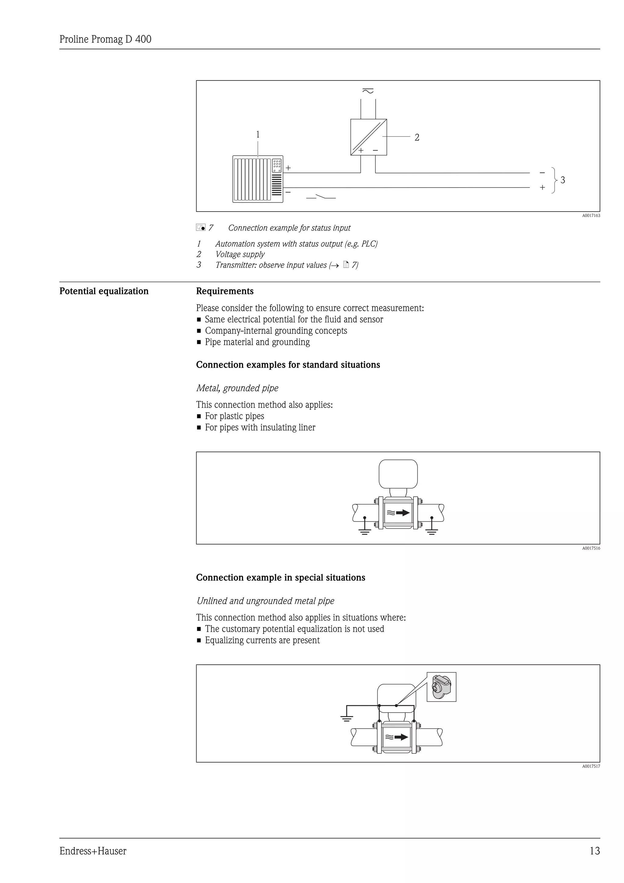
Input signal Status input
Maximum input values • DC 30 V
• 6 mA
Response time Adjustable: 5 to 200 ms
Input signal level • Low signal: DC –3 to +5 V
• High signal: DC 12 to 30 V
Assignable functions • Off
• Reset totalizers 1-3 separately
• Reset all totalizers
• Flow override
Output
Output signal Current output
Current output Can be set as:
• 4-20 mA HART (active)
• 0-20 mA (active)
Maximum output values • DC 24 V (when idle)
• 22.5 mA
Load 0 to 700 Ω
Resolution 0.5 µA
Damping Adjustable: 0 to 999 s
Assignable measured • Volume flow
variables • Conductivity
• Mass flow
6 Endress+Hauser](https://image.slidesharecdn.com/ti01044den0112prolinepromagd400-130328210344-phpapp01/75/Electromagnetic-flowmeter-Proline-Promag-D-400-6-2048.jpg)


![Proline Promag D 400
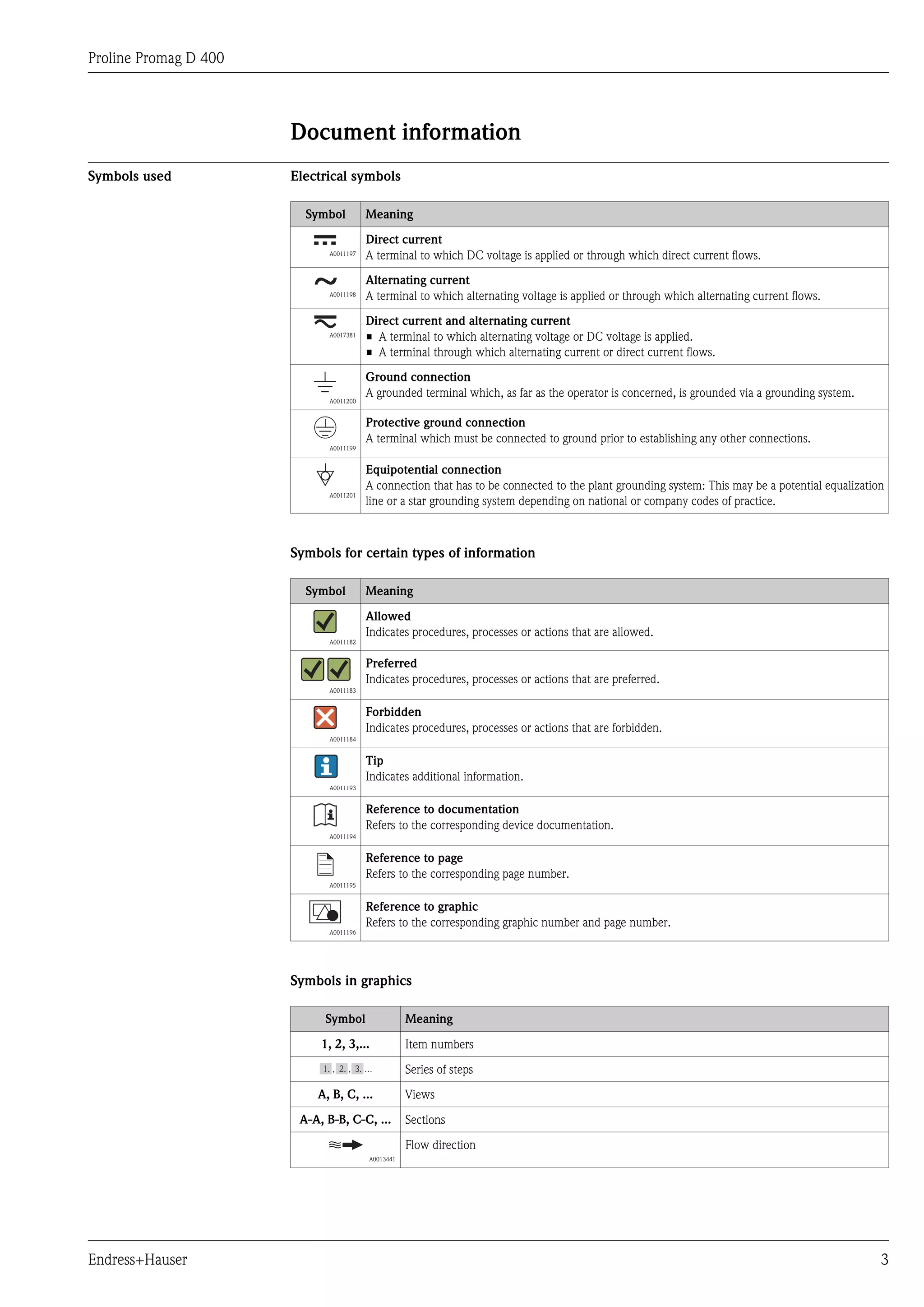
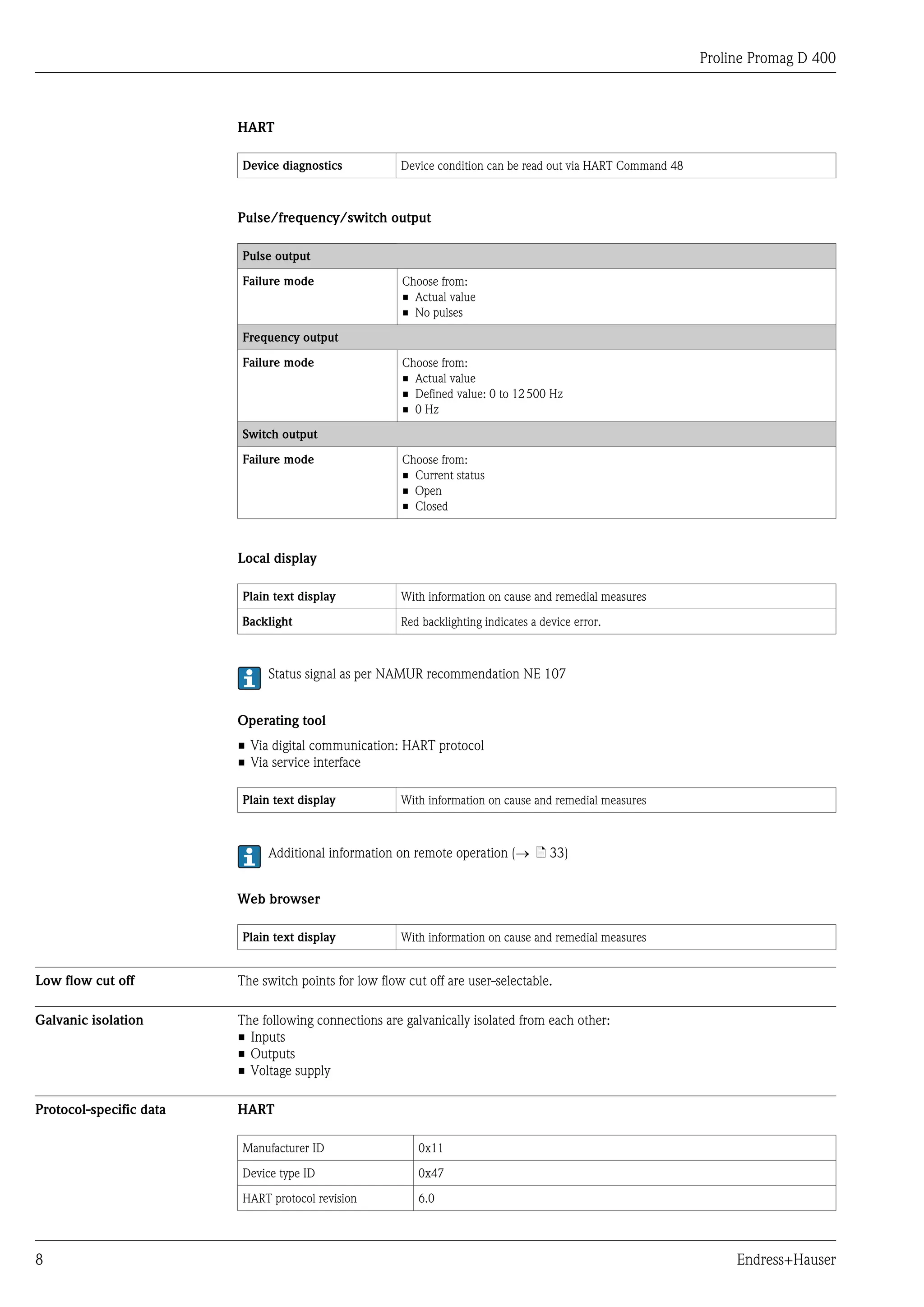
Pulse output
±0.5 % o.r.± 1 mm/s (0.04 in/s)
Fluctuations in the supply voltage do not have any effect within the specified range.
[%]
2.5
2.0
0.5 %
1.5
1.0
0.5
0
0 1 2 4 6 8 10 [m/s]
v
0 5 10 15 20 25 30 32 [ft/s]
A0003200
å9 Maximum measured error in % o.r.
Repeatability o.r. = of reading
max. ±0.1 % o.r. ± 0.5 mm/s (0.02 in/s)
Influence of ambient o.r. = of reading; o.f.s. = of full scale value
temperature
Current output
Temperature coefficient Typically ±50 ppm/°C o.r. or ±1 µA/°C
Pulse/frequency output
Temperature coefficient Max.±50 ppm/°C
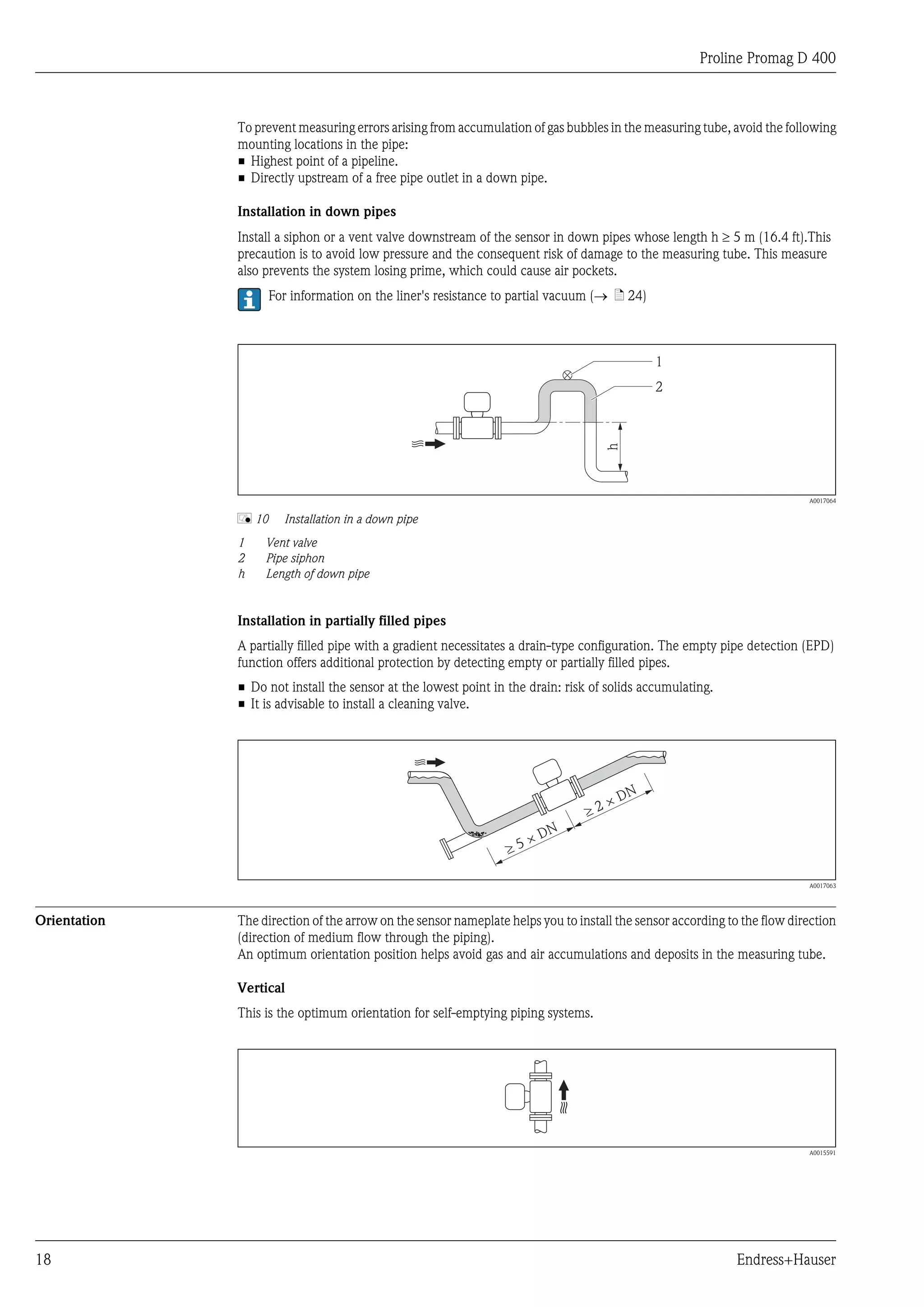
Installation
No special measures such as supports are necessary. External forces are absorbed by the construction of the
device.
Mounting location Preferably install the sensor in an ascending pipe, and ensure a sufficient distance to the next pipe elbow: h =
³ 2 × DN
h
A0017061
Endress+Hauser 17](https://image.slidesharecdn.com/ti01044den0112prolinepromagd400-130328210344-phpapp01/75/Electromagnetic-flowmeter-Proline-Promag-D-400-17-2048.jpg)
![Proline Promag D 400
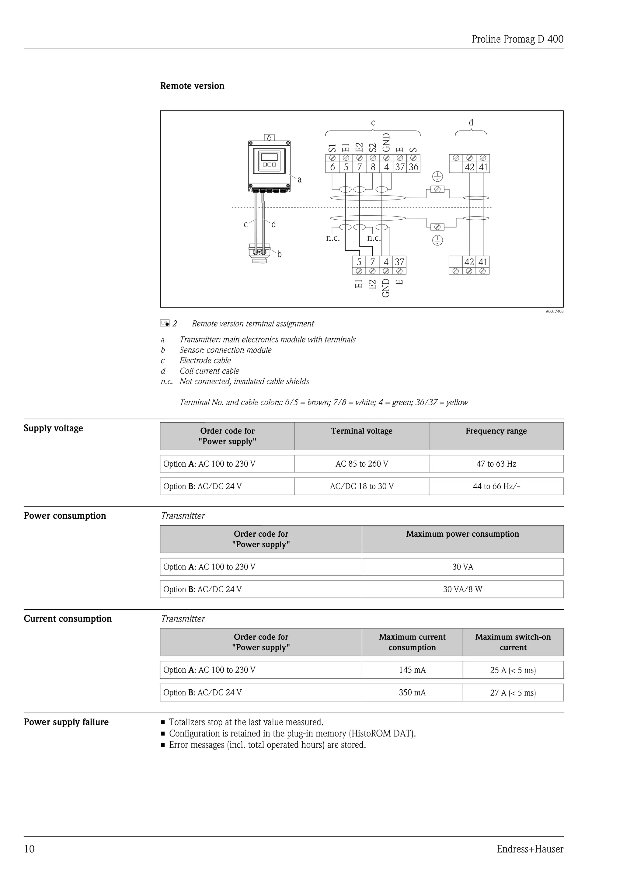
[mbar] 100
8 m/s
7 m/s
6 m/s
10
5 m/s
max. 8° 4 m/s
3 m/s
d D
2 m/s
1
1 m/s
d/D 0.5 0.6 0.7 0.8 0.9
A0016359
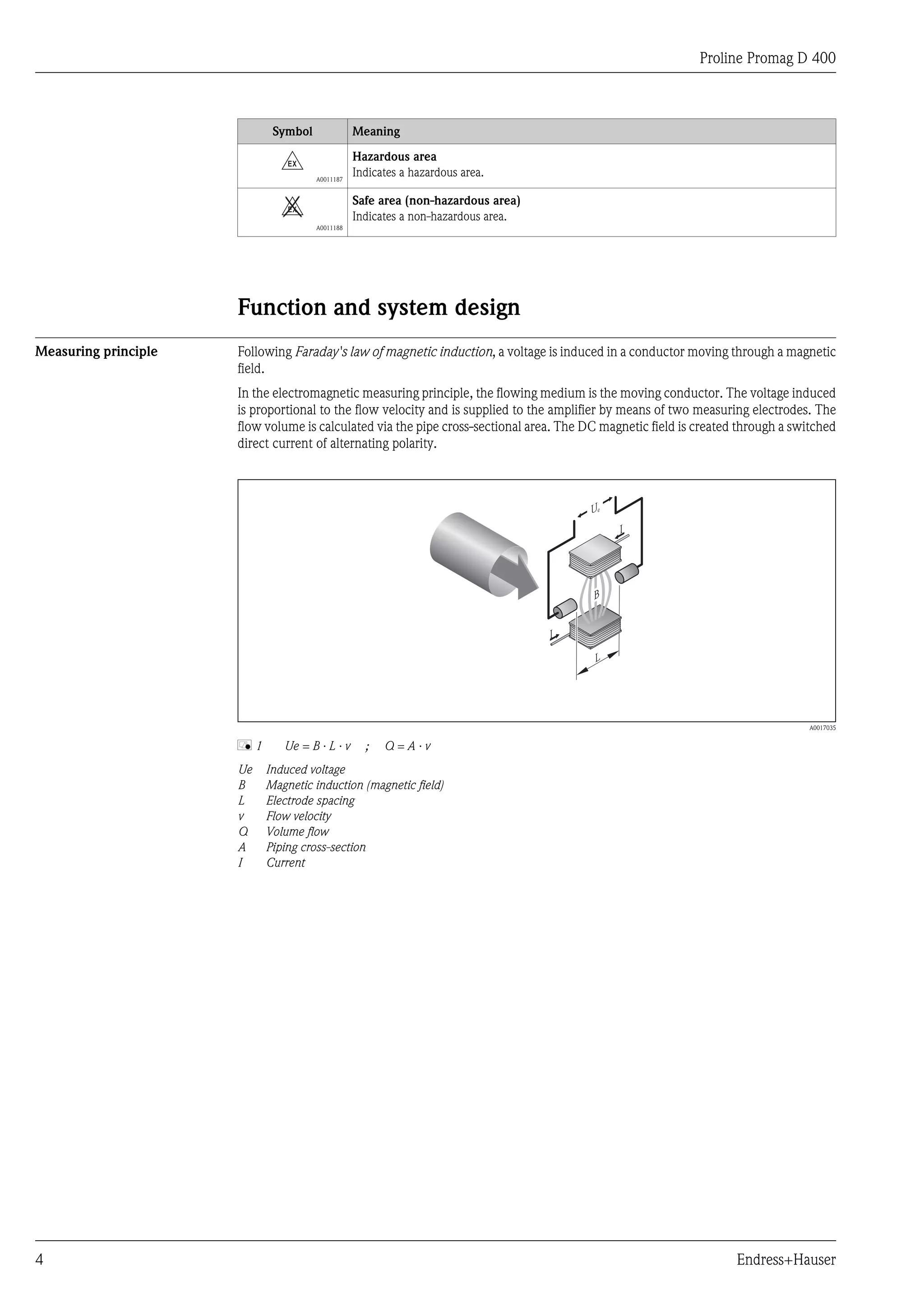
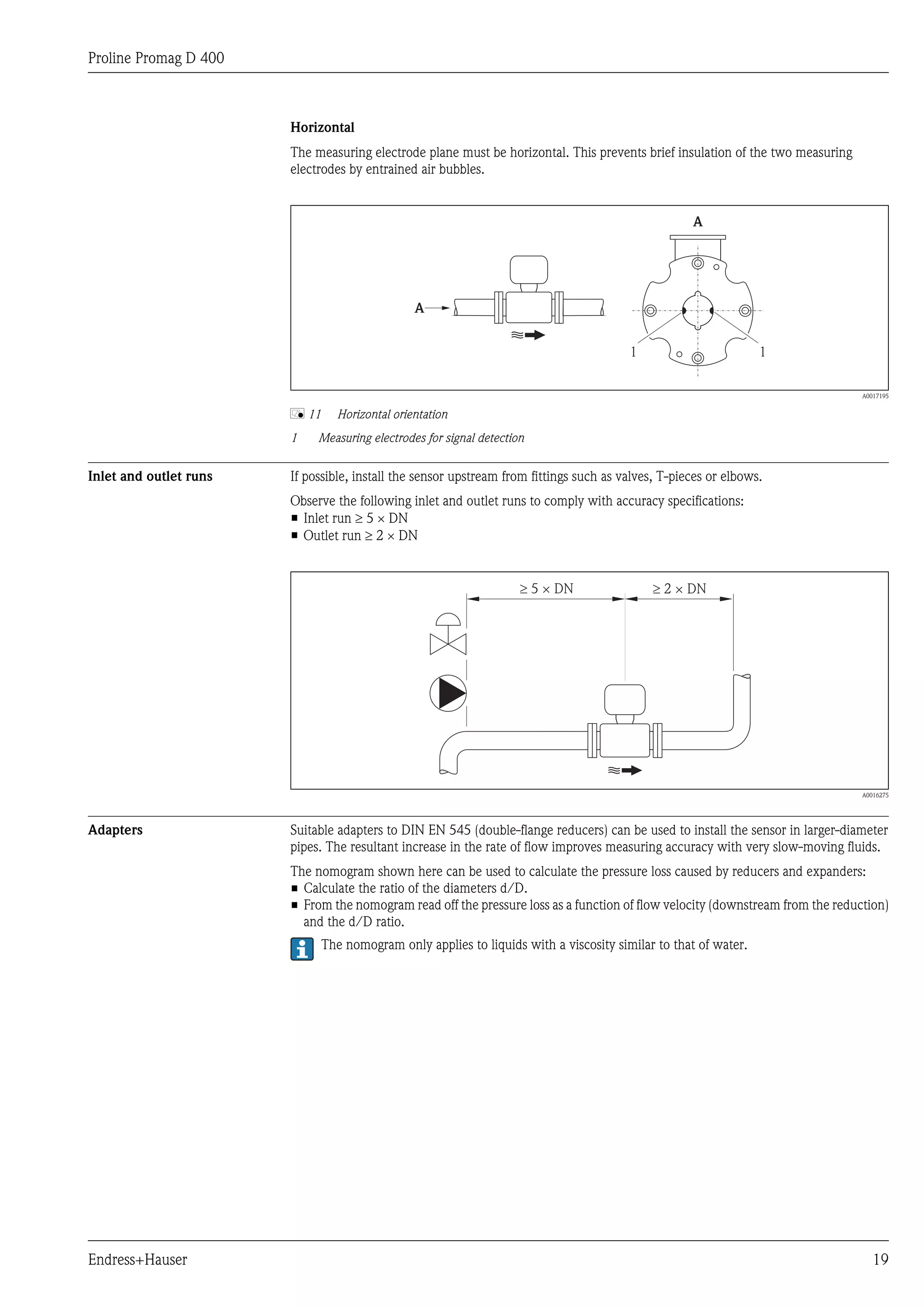
Mounting kit The sensor is installed between the pipe flanges using a mounting kit. The device is centered using the recesses
on the sensor. Centering sleeves are also provided depending on the flange standard or the diameter of the
pitch circle.
A mounting kit – consisting of mounting bolts, seals, nuts and washers – can be ordered separately (see
"Accessories" section (® ä 35)).
5
1
2
3
4
A0018060
å 12 Mounting the sensor
1 Nut
2 Washer
3 Mounting bolts
4 Centering sleeve
5 Seal
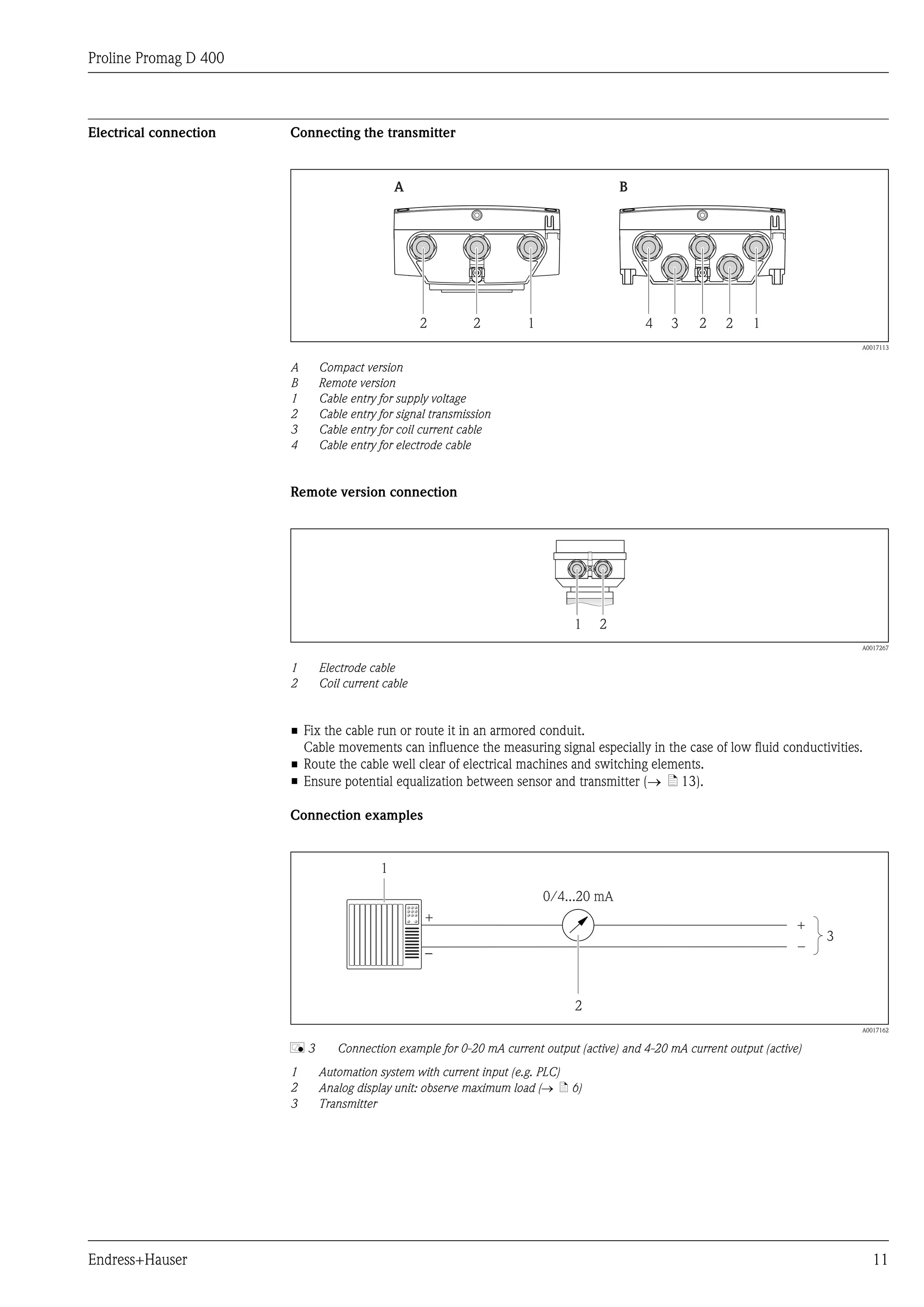
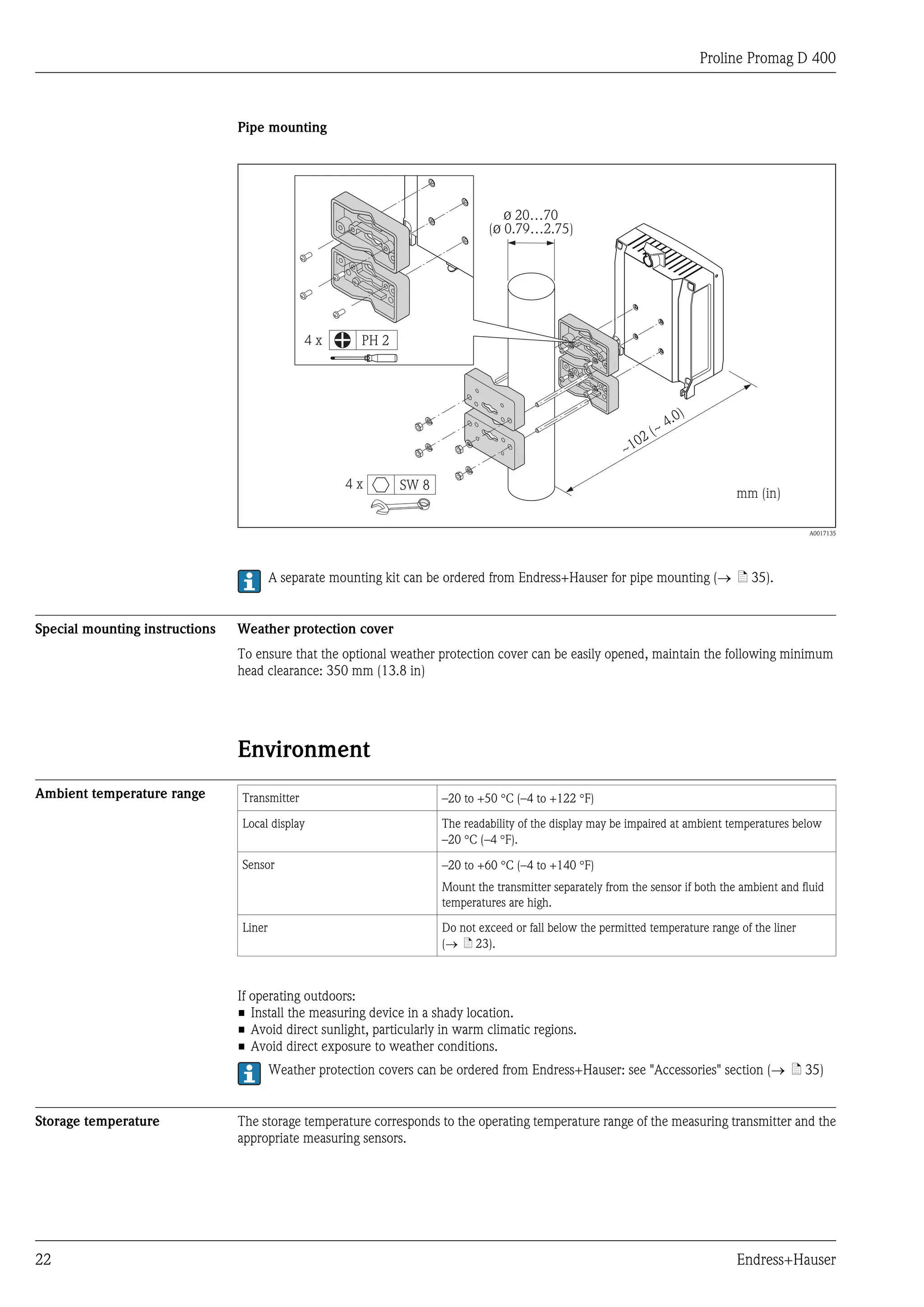
Length of connecting cable To ensure correct measuring results when using the remote version,
observe the maximum permitted cable length Lmax. This length is determined by the conductivity of the fluid.
– If measuring liquids in general: 5 mS/cm
– If measuring demineralized water: 20 mS/cm
20 Endress+Hauser](https://image.slidesharecdn.com/ti01044den0112prolinepromagd400-130328210344-phpapp01/75/Electromagnetic-flowmeter-Proline-Promag-D-400-20-2048.jpg)
![Proline Promag D 400
[µS/cm]
200
100
L max
5 [m]
10 100 200 L max
[ft]
0 200 400 600
A0016539
å 13 Permitted length of connecting cable for remote version
Area shaded gray = permitted range
Lmax = length of connecting cable in [m] ([ft])
[mS/cm] = fluid conductivity
Installing the wall-mount Wall mounting
housing
18 (0.71) = =
14 (0.55)
5.8 (0.23)
210.5 (8.29)
5.8 (0.23)
mm (in) 149 (5.85)
A0017138
Endress+Hauser 21](https://image.slidesharecdn.com/ti01044den0112prolinepromagd400-130328210344-phpapp01/75/Electromagnetic-flowmeter-Proline-Promag-D-400-21-2048.jpg)
![Proline Promag D 400
• Protect the measuring device against direct sunlight during storage in order to avoid unacceptably high surface
temperatures.
• Select a storage location where moisture cannot collect in the measuring device as fungus or bacteria
infestation can damage the liner.
• If protection caps or protective covers are mounted these should never be removed before installing the
measuring device.
Atmosphere If a plastic transmitter housing is permanently exposed to certain steam and air mixtures, this can damage the
housing.
If you are unsure, please contact your Endress+Hauser Sales Center for clarification.
Degree of protection Transmitter
• As standard: IP66/67, type 4X enclosure
• When housing is open: IP20, type 1 enclosure
Sensor
As standard: IP66/67, type 4X enclosure
Shock resistance Acceleration up to 2 g following IEC 600 68-2-6
Vibration resistance Acceleration up to 2 g following IEC 600 68-2-6
Mechanical load • Protect the transmitter housing against mechanical effects, such as shock or impact; the use of the remote
version is sometimes preferable.
• Never use the transmitter housing as a ladder or climbing aid.
Electromagnetic compatibility • As per IEC/EN 61326 and NAMUR Recommendation 21 (NE 21)
(EMC) • Complies with emission limits for industry as per EN 55011 (Class A)
Details are provided in the Declaration of Conformity.
Process
Medium temperature range 0 to +60 °C (+32 to +140 °F) for polyamide
Conductivity • ³ 5 mS/cm for liquids in general
• ³ 20 mS/cm for demineralized water
Note that in the case of the remote version, the requisite minimum conductivity also depends on the cable
length (® ä 20).
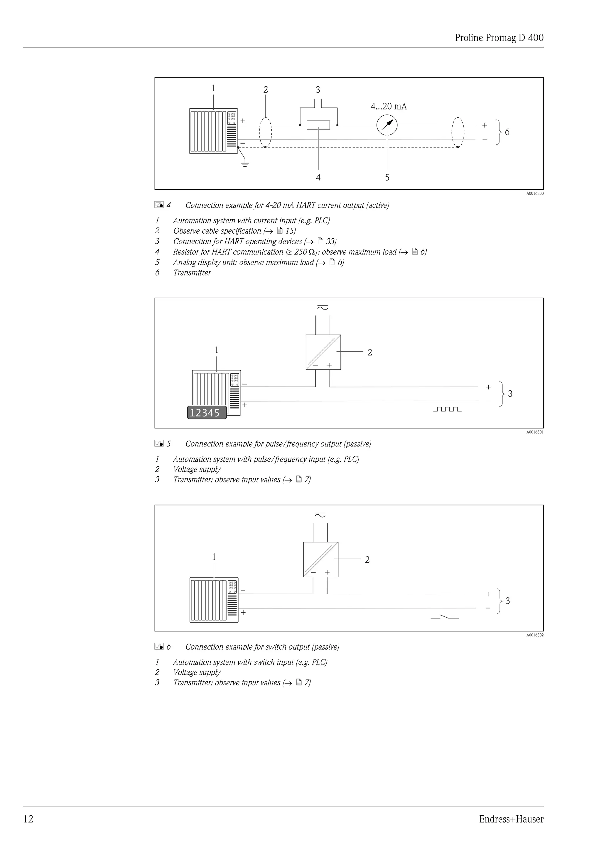
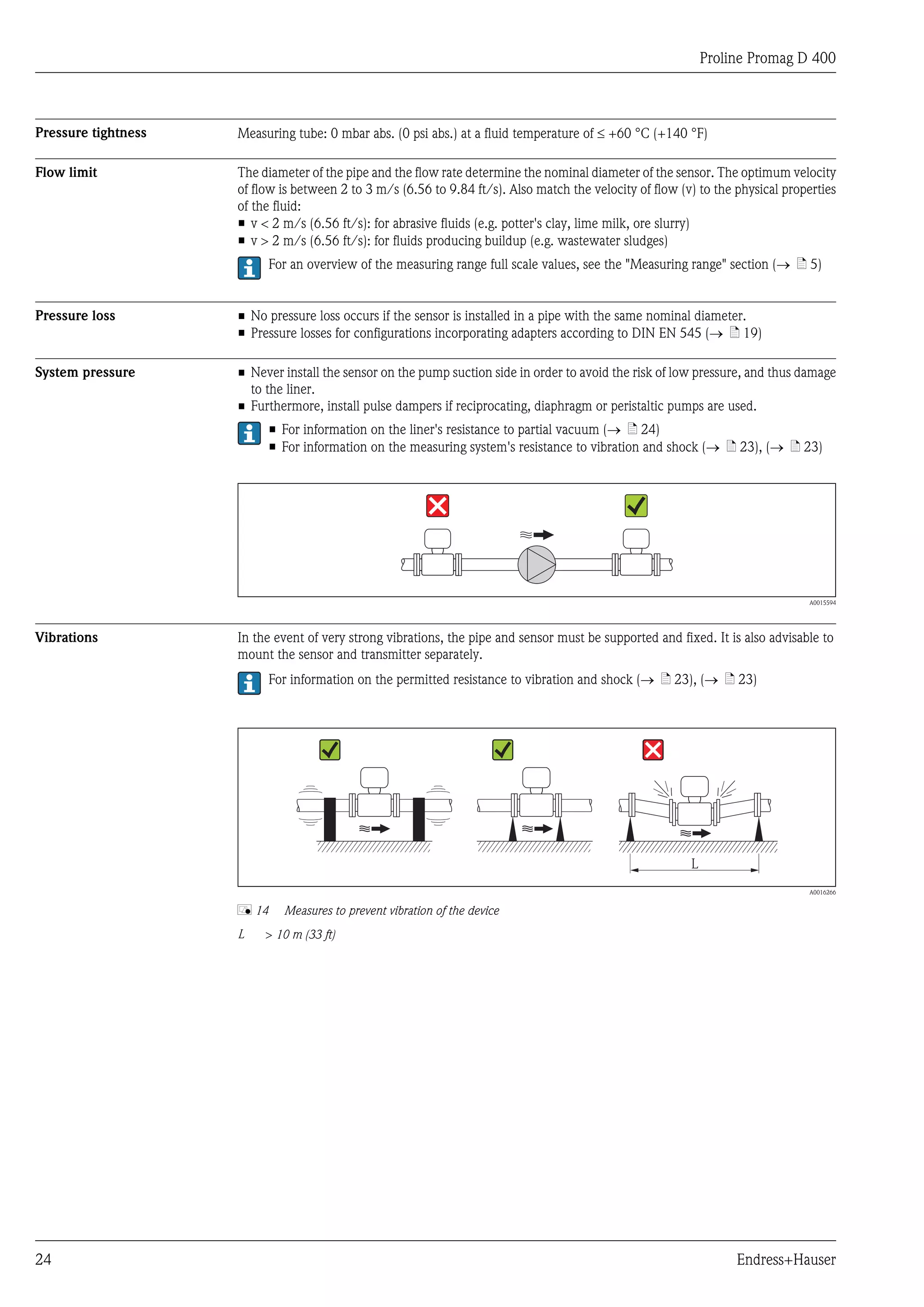
Pressure-temperature ratings Permitted process pressure
[psi] [bar]
280 20
240 16
200
160 12
120 8
80
4
40
0 0
0 5 10 15 20 25 30 35 40 45 50 55 60 65 [°C]
30 40 50 60 70 80 90 100 110 120 130 140 150 [°F]
A0017088
Endress+Hauser 23](https://image.slidesharecdn.com/ti01044den0112prolinepromagd400-130328210344-phpapp01/75/Electromagnetic-flowmeter-Proline-Promag-D-400-23-2048.jpg)
![Proline Promag D 400
Mechanical construction
Design, dimensions Compact version
Order code for "Housing", option M "Compact, polycarbonate"
A C
B
D
E
F
G
H
e1
e1 e1
e2
d2 d2 d2
d1 d1 d1
DN 25…40 DN 50 DN 65…100 mm
(1"…1½" ) (2") (2½"…4") (in)
A0017147
Dimensions in SI units
DN 1) A B C D E F G H d1 d2 e 1 2)
[mm] [mm] [mm] [mm] [mm] [mm] [mm] [mm] [mm] [mm] [mm] [mm]
25 216 189 165 84 164 207 43 55 86 24 68
40 216 189 165 84 175 227 52 69 104 38 87
50 216 189 165 84 186 248 62 83 124 50 106
65 216 189 165 84 196 266 70 93 139 60 125
80 216 189 165 84 200 275 75 117 151 76 135
100 216 189 165 84 214 303 89 148 179 97 160
1) EN (DIN), JIS
2) max. Æ seals
Endress+Hauser 25](https://image.slidesharecdn.com/ti01044den0112prolinepromagd400-130328210344-phpapp01/75/Electromagnetic-flowmeter-Proline-Promag-D-400-25-2048.jpg)
![Proline Promag D 400
Dimensions in US units
DN 1) A B C D E F G H d1 d2 e 1 2) e 2 2)
[in] [in] [in] [in] [in] [in] [in] [in] [in] [in] [in] [in] [in]
1 8.50 7.44 6.50 3.31 6.46 8.15 1.69 2.17 3.39 0.94 2.68 –
1½ 8.50 7.44 6.50 3.31 6.89 8.94 2.05 2.72 4.11 1.50 3.43 –
2 8.50 7.44 6.50 3.31 7.32 9.76 2.44 3.27 4.88 1.97 4.17 –
3 8.50 7.44 6.50 3.31 7.72 10.5 2.95 4.61 5.94 2.99 – 5.43
4 8.50 7.44 6.50 3.31 7.87 10.8 3.50 5.83 7.05 3.82 6.30 –
1) ASME
2) max. Æ seals
Transmitter remote version
Order code for "Housing", option N "Remote, polycarbonate"
D
B
E
C
A F
G
K
L
J H J
A0017148
Dimensions in SI units
A B C D E F
[mm] [mm] [mm] [mm] [mm] [mm]
165 185 15 25 225 80
26 Endress+Hauser](https://image.slidesharecdn.com/ti01044den0112prolinepromagd400-130328210344-phpapp01/75/Electromagnetic-flowmeter-Proline-Promag-D-400-26-2048.jpg)
![Proline Promag D 400
G H J K L
[mm] [mm] [mm] [mm] [mm]
50 53 56 88.5 53
Dimensions in US units
A B C D E F
[in] [in] [in] [in] [in] [in]
6.5 7.28 0.59 0.98 8.86 3.15
G H J K L
[in] [in] [in] [in] [in]
1.97 2.09 2.2 3.48 2.09
Sensor remote version
B
A C
E
F
H
G
D e1
e1 e1 e2
d2 d2 d2
d1 d1 d1
DN 25…40 DN 50 DN 65…100 mm
(1"…1½") (2") (2½"…4") (in)
A0010717
Dimensions in SI units
DN 1) A B C D E F G H d1 d2 e 1 2)
[mm] [mm] [mm] [mm] [mm] [mm] [mm] [mm] [mm] [mm] [mm] [mm]
25 129 163 143 55 102 192 43 235 86 24 68
40 129 163 143 69 102 203 52 255 104 38 87
50 129 163 143 83 102 214 62 276 124 50 106
Endress+Hauser 27](https://image.slidesharecdn.com/ti01044den0112prolinepromagd400-130328210344-phpapp01/75/Electromagnetic-flowmeter-Proline-Promag-D-400-27-2048.jpg)
![Proline Promag D 400
DN 1) A B C D E F G H d1 d2 e 1 2)
[mm] [mm] [mm] [mm] [mm] [mm] [mm] [mm] [mm] [mm] [mm] [mm]
65 129 163 143 93 102 224 70 294 139 60 125
80 129 163 143 117 102 228 75 303 151 76 135
100 129 163 143 148 102 242 89 331 179 97 160
1) EN (DIN), JIS
2) max. Æ seals
Dimensions in US units
DN 1) A B C D E F G H d1 d2 e 1 2) e 2 2)
[in] [in] [in] [in] [in] [in] [in] [in] [in] [in] [in] [in] [in]
1 5.08 6.42 5.63 2.17 4.02 7.56 1.69 9.25 3.39 0.94 2.68 –
1½ 5.08 6.42 5.63 2.72 4.02 7.99 2.05 10.0 4.11 1.50 3.43 –
2 5.08 6.42 5.63 3.27 4.02 8.43 2.44 10.9 4.88 1.97 4.17 –
3 5.08 6.42 5.63 4.61 4.02 8.98 2.95 11.9 5.94 2.99 – 5.43
4 5.08 6.42 5.63 5.83 4.02 9.53 3.50 13.0 7.05 3.82 6.30 –
1) ASME
2) max. Æ seals
Weight Compact version
Weight data:
• Including the transmitter (1.15 kg (2.54 lbs))
• Excluding packaging material
Weight in SI units
Nominal diameter EN (DIN), JIS
[mm] [in] [kg]
25 1 4.5
40 1½ 5.1
50 2 5.9
65 – 6.7
80 3 7.7
100 4 10.4
Weight in US units
Nominal diameter ASME
[mm] [in] [lbs]
25 1 9.9
40 1½ 11.2
50 2 13.0
65 – 14.8
80 3 17.0
100 4 22.9
28 Endress+Hauser](https://image.slidesharecdn.com/ti01044den0112prolinepromagd400-130328210344-phpapp01/75/Electromagnetic-flowmeter-Proline-Promag-D-400-28-2048.jpg)
![Proline Promag D 400
Transmitter remote version
1.15 kg (2.54 lb)
Sensor remote version
Weight data:
• Including the transmitter housing
• Excluding the connecting cable
• Excluding packaging material
Weight in SI units
Nominal diameter EN (DIN), JIS
[mm] [in] [kg]
25 1 2.5
40 1½ 3.1
50 2 3.9
65 – 4.7
80 3 5.7
100 4 8.4
Weight in US units
Nominal diameter ASME
[mm] [in] [lbs]
25 1 5.5
40 1½ 6.8
50 2 8.6
65 – 10.4
80 3 12.6
100 4 18.5
Measuring tube specification Pressure rating EN (DIN)
Nominal diameter Pressure rating Mounting bolts Length internal diameter
Centering sleeves Measuring tube
[mm] [in] [mm] [in] [mm] [in] [mm] [in]
25 1 PN 16 4 ´ M12 ´ 145 5.71 54 2.13 24 0.94
40 1½ PN 16 4 ´ M16 ´ 170 6.69 68 2.68 38 1.50
50 2 PN 16 4 ´ M16 ´ 185 7.28 82 3.23 50 1.97
65 1) – PN 16 4 ´ M16 ´ 200 7.87 92 3.62 60 2.36
2) 3) 3)
65 – PN 16 8 ´ M16 ´ 200 7.87 – – 60 2.36
80 3 PN 16 8 ´ M16 ´ 225 8.86 116 4.57 76 2.99
100 4 PN 16 8 ´ M16 ´ 260 10.24 147 5.79 97 3.82
1) EN (DIN) flange: 4-hole ® with centering sleeves
2) EN (DIN) flange: 8-hole ® without centering sleeves
3) A centering sleeve is not required. The device is centered directly via the sensor housing.
Endress+Hauser 29](https://image.slidesharecdn.com/ti01044den0112prolinepromagd400-130328210344-phpapp01/75/Electromagnetic-flowmeter-Proline-Promag-D-400-29-2048.jpg)
![Proline Promag D 400
ASME pressure rating
Nominal diameter Pressure rating Mounting bolts Length internal diameter
Centering sleeves Measuring tube
[mm] [in] [mm] [in] [mm] [in] [mm] [in]
1) 1)
25 1 Class 150 4 ´ UNC ½" ´ 145 5.70 – – 24 0.94
1) 1)
40 1½ Class 150 4 ´ UNC ½" ´ 165 6.50 – – 38 1.50
1) 1)
50 2 Class 150 4 ´ UNC 5/8" ´ 190.5 7.50 – – 50 1.97
1) 1)
80 3 Class 150 8 ´ UNC 5/8" ´ 235 9.25 – – 76 2.99
100 4 Class 150 8 ´ UNC 5/8" ´ 264 10.4 147 5.79 97 3.82
1) A centering sleeve is not required. The device is centered directly via the sensor housing.
Pressure rating JIS
Nominal diameter Pressure rating Mounting bolts Length internal diameter
Centering sleeves Measuring tube
[mm] [in] [mm] [in] [mm] [in] [mm] [in]
25 1 10K 4 ´ M16 ´ 170 6.69 54 2.13 24 0.94
40 1½ 10K 4 ´ M16 ´ 170 6.69 68 2.68 38 1.50
50 2 10K 4 ´ M16 ´ 185 7.28 – 1) – 1) 50 1.97
65 – 10K 4 ´ M16 ´ 200 7.87 – 1) – 1) 60 2.36
1) 1)
80 3 10K 8 ´ M16 ´ 225 8.86 – – 76 2.99
1) 1)
100 4 10K 8 ´ M16 ´ 260 10.24 – – 97 3.82
1) A centering sleeve is not required. The device is centered directly via the sensor housing.
Materials Transmitter housing
• Order code for "Housing", option M, N: polycarbonate plastic
• Window material: polycarbonate plastic
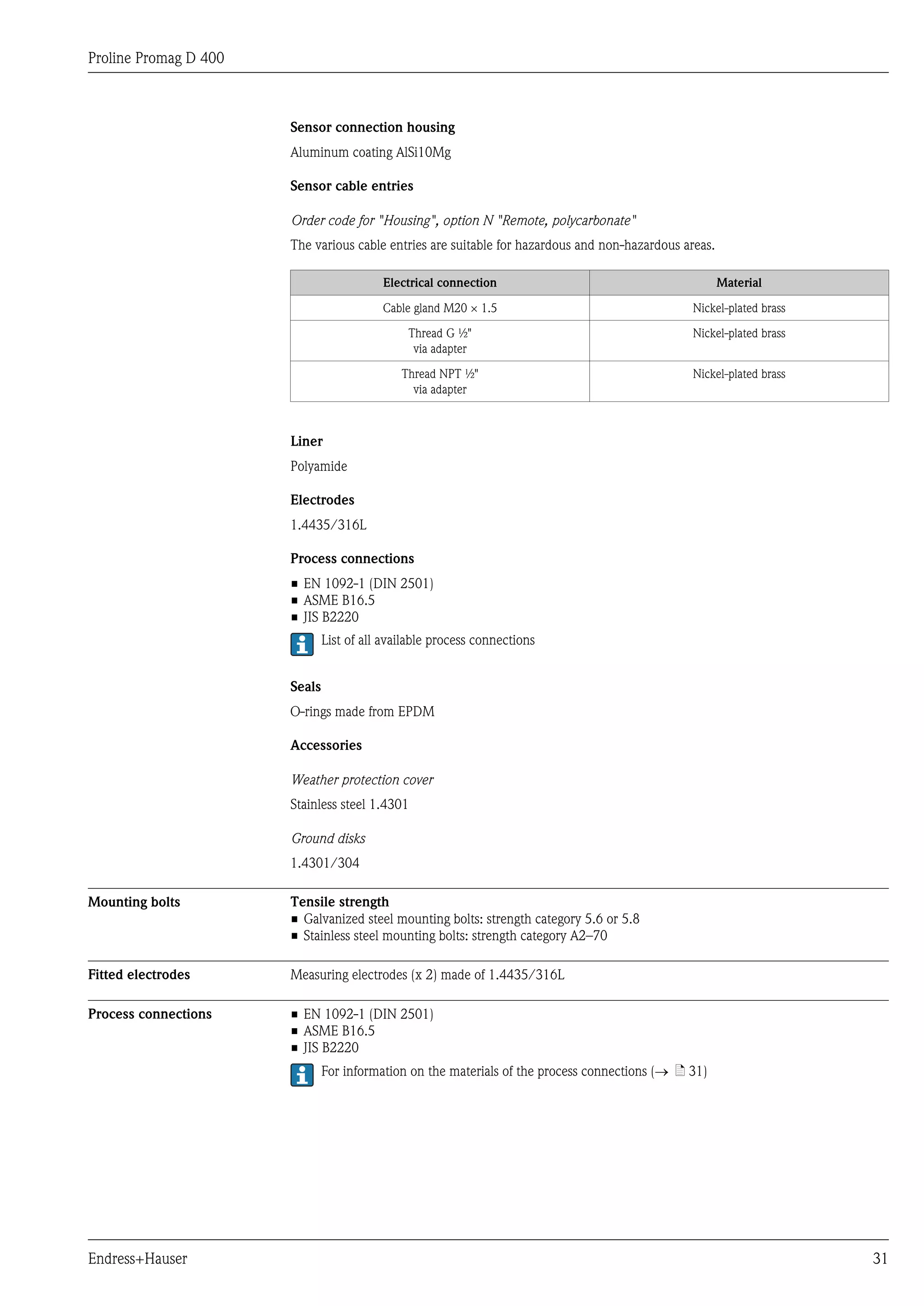
Transmitter cable entries
Order code for "Housing", option M "Compact, polycarbonate"; option N "Remote, polycarbonate"
The various cable entries are suitable for hazardous and non-hazardous areas.
Electrical connection Material
Cable gland M20 × 1.5 Plastic
Thread G ½" Nickel-plated brass
via adapter
Thread NPT ½" Nickel-plated brass
via adapter
Connecting cable for remote version
• Electrode cable: PVC cable with copper shield
• Coil current cable: PVC cable with copper shield
Sensor housing
Aluminum coating AlSi10Mg
30 Endress+Hauser](https://image.slidesharecdn.com/ti01044den0112prolinepromagd400-130328210344-phpapp01/75/Electromagnetic-flowmeter-Proline-Promag-D-400-30-2048.jpg)


The Proline Promag D 400 is a lightweight, compact electromagnetic flowmeter designed for efficient, bidirectional measurement of liquids in water applications with a minimum conductivity of 3-5 mS/cm. Its self-centering design, pressure and temperature insensitivity, and easy installation make it suitable for a range of water industry requirements, offering features such as multiple outputs, diagnostics, and intuitive commissioning tools. The flowmeter is constructed with durable materials and complies with various global drinking water approvals.


![Vibe Coding vs. Spec-Driven Development [Free Meetup]](https://cdn.slidesharecdn.com/ss_thumbnails/vibecodingvsspecdrivendevelopment-251209105622-43f455e7-thumbnail.jpg?width=640&height=640&fit=bounds)


