Voltage dividers
•
2 likes•144 views

Voltage dividers consist of two resistors connected in series across a supply voltage. The output voltage depends on the relative sizes of the two resistors - if R2 is much smaller than R1, the output voltage will be small, and if R2 is much larger, the output voltage will be high. Voltage dividers are commonly used with sensors to convert a varying resistance to a varying output voltage. The sensor replaces one of the resistors, and its position determines whether a high or low sensor resistance gives a high output voltage. The other resistor should be chosen to give a large output voltage range, using the formula R = square root of (Rmin x Rmax).

Recommended
More Related Content
What's hot
What's hot (20)
Viewers also liked
Similar to Voltage dividers
Similar to Voltage dividers (20)
Recently uploaded
Recently uploaded (20)
Voltage dividers
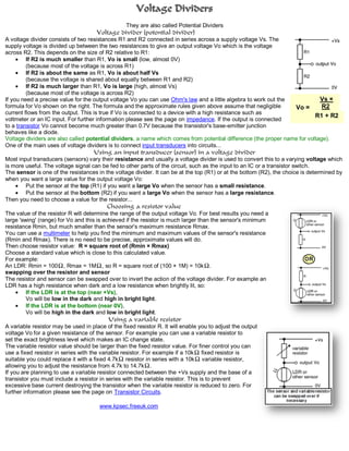
- 1. Voltage Dividers They are also called Potential Dividers Voltage divider (potential divider) A voltage divider consists of two resistances R1 and R2 connected in series across a supply voltage Vs. The supply voltage is divided up between the two resistances to give an output voltage Vo which is the voltage across R2. This depends on the size of R2 relative to R1: If R2 is much smaller than R1, Vo is small (low, almost 0V) (because most of the voltage is across R1) If R2 is about the same as R1, Vo is about half Vs (because the voltage is shared about equally between R1 and R2) If R2 is much larger than R1, Vo is large (high, almost Vs) (because most of the voltage is across R2) If you need a precise value for the output voltage Vo you can use Ohm's law and a little algebra to work out the Vs × formula for Vo shown on the right. The formula and the approximate rules given above assume that negligible Vo = R2 current flows from the output. This is true if Vo is connected to a device with a high resistance such as R1 + R2 voltmeter or an IC input. For further information please see the page on impedance. If the output is connected to a transistor Vo cannot become much greater than 0.7V because the transistor's base-emitter junction behaves like a diode. Voltage dividers are also called potential dividers, a name which comes from potential difference (the proper name for voltage). One of the main uses of voltage dividers is to connect input transducers into circuits... Using an input transducer (sensor) in a voltage divider Most input transducers (sensors) vary their resistance and usually a voltage divider is used to convert this to a varying voltage which is more useful. The voltage signal can be fed to other parts of the circuit, such as the input to an IC or a transistor switch. The sensor is one of the resistances in the voltage divider. It can be at the top (R1) or at the bottom (R2), the choice is determined by when you want a large value for the output voltage Vo: Put the sensor at the top (R1) if you want a large Vo when the sensor has a small resistance. Put the sensor at the bottom (R2) if you want a large Vo when the sensor has a large resistance. Then you need to choose a value for the resistor... Choosing a resistor value The value of the resistor R will determine the range of the output voltage Vo. For best results you need a large 'swing' (range) for Vo and this is achieved if the resistor is much larger than the sensor's minimum resistance Rmin, but much smaller than the sensor's maximum resistance Rmax. You can use a multimeter to help you find the minimum and maximum values of the sensor's resistance (Rmin and Rmax). There is no need to be precise, approximate values will do. Then choose resistor value: R = square root of (Rmin × Rmax) Choose a standard value which is close to this calculated value. For example: An LDR: Rmin = 100 , Rmax = 1M , so R = square root of (100 × 1M) = 10k . swapping over the resistor and sensor The resistor and sensor can be swapped over to invert the action of the voltage divider. For example an LDR has a high resistance when dark and a low resistance when brightly lit, so: If the LDR is at the top (near +Vs), Vo will be low in the dark and high in bright light. If the LDR is at the bottom (near 0V), Vo will be high in the dark and low in bright light. Using a variable resistor A variable resistor may be used in place of the fixed resistor R. It will enable you to adjust the output voltage Vo for a given resistance of the sensor. For example you can use a variable resistor to set the exact brightness level which makes an IC change state. The variable resistor value should be larger than the fixed resistor value. For finer control you can use a fixed resistor in series with the variable resistor. For example if a 10k fixed resistor is suitable you could replace it with a fixed 4.7k resistor in series with a 10k variable resistor, allowing you to adjust the resistance from 4.7k to 14.7k . If you are planning to use a variable resistor connected between the +Vs supply and the base of a transistor you must include a resistor in series with the variable resistor. This is to prevent excessive base current destroying the transistor when the variable resistor is reduced to zero. For further information please see the page on Transistor Circuits. www.kpsec.freeuk.com